Mining System Installation Guide
Page 1
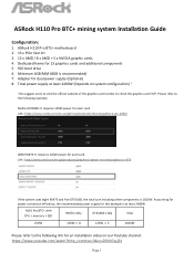
... for power conversion efficiency, the recommended power supply for each card. ASRock H110 Pro BTC+ motherboard 2. 13 x PCIe riser kit 3. 13 x AMD / 8 x AMD + 5 x NVIDIA graphic cards. 4. SSD boot drive 6. H110 Pro BTC+ with CPU + memory + SSD RX470 x Qty GTX1060 x Qty Total 250W... 120W x 8 120W x 5 1810W Please refer to the following link for each card. ASRock H110 Pro BTC+ mining system Installation Guide Configuration: 1. Link: https://www....
... for power conversion efficiency, the recommended power supply for each card. ASRock H110 Pro BTC+ motherboard 2. 13 x PCIe riser kit 3. 13 x AMD / 8 x AMD + 5 x NVIDIA graphic cards. 4. SSD boot drive 6. H110 Pro BTC+ with CPU + memory + SSD RX470 x Qty GTX1060 x Qty Total 250W... 120W x 8 120W x 5 1810W Please refer to the following link for each card. ASRock H110 Pro BTC+ mining system Installation Guide Configuration: 1. Link: https://www....
Mining System Installation Guide
Page 3
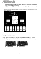
... 2400W for power connections (not including the required connections to turn on the power supply by shorting the specific wire on the H110 Pro BTC+. Please install the Skylake or Kaby Lake CPU and DDR4 memory on the 24pin ATX cable. b. Please refer to install the system: Step 1. Page 3 Plug the graphics card into...
... 2400W for power connections (not including the required connections to turn on the power supply by shorting the specific wire on the H110 Pro BTC+. Please install the Skylake or Kaby Lake CPU and DDR4 memory on the 24pin ATX cable. b. Please refer to install the system: Step 1. Page 3 Plug the graphics card into...
Mining System Installation Guide
Page 5
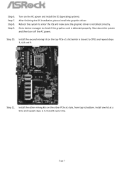
... graphics driver is installed correctly. Shut down the system and then turn off the AC power. Install the other PCIe x1 slots, from top to CPU) and repeat steps 3, 4, 8 and 9. Install one kit at a time and repeat steps 3, 4, 8 and 9 every time. Step 9. Install the second mining kit on the other mining...
... graphics driver is installed correctly. Shut down the system and then turn off the AC power. Install the other PCIe x1 slots, from top to CPU) and repeat steps 3, 4, 8 and 9. Install one kit at a time and repeat steps 3, 4, 8 and 9 every time. Step 9. Install the second mining kit on the other mining...
User Manual
Page 4
...Specifications 2 1.3 Motherboard Layout 6 1.4 I/O Panel 8 Chapter 2 Installation 10 2.1 Installing the CPU 11 2.2 Installing the CPU Fan and Heatsink 14 2.3 Installing Memory Modules (DIMM) 15 2.4 Expansion Slots (PCI Express... Slots) 17 2.5 Jumpers Setup 18 2.6 Onboard Headers and Connectors 19 2.7 PCIe Power Connector Installation Guide 23 2.8 M.2_SSD (NGFF) Module Installation Guide 24 Chapter 3 Software and Utilities Operation 27 3.1 Installing Drivers 27 3.2 ASRock...
...Specifications 2 1.3 Motherboard Layout 6 1.4 I/O Panel 8 Chapter 2 Installation 10 2.1 Installing the CPU 11 2.2 Installing the CPU Fan and Heatsink 14 2.3 Installing Memory Modules (DIMM) 15 2.4 Expansion Slots (PCI Express... Slots) 17 2.5 Jumpers Setup 18 2.6 Onboard Headers and Connectors 19 2.7 PCIe Power Connector Installation Guide 23 2.8 M.2_SSD (NGFF) Module Installation Guide 24 Chapter 3 Software and Utilities Operation 27 3.1 Installing Drivers 27 3.2 ASRock...
User Manual
Page 5
Chapter 4 UEFI SETUP UTILITY 37 4.1 Introduction 37 4.1.1 UEFI Menu Bar 37 4.1.2 Navigation Keys 38 4.2 Main Screen 39 4.3 OC Tweaker Screen 40 4.4 Advanced Screen 48 4.4.1 CPU Configuration 49 4.4.2 Chipset Configuration 51 4.4.3 Storage Configuration 54 4.4.4 Super IO Configuration 55 4.4.5 ACPI Configuration 56 4.4.6 USB Configuration 58 4.4.7 Trusted Computing 59 4.5 Tools 60 4.6 Hardware Health Event Monitoring Screen 61 4.7 Security Screen 63 4.8 Boot Screen 64 4.9 Exit Screen 67
Chapter 4 UEFI SETUP UTILITY 37 4.1 Introduction 37 4.1.1 UEFI Menu Bar 37 4.1.2 Navigation Keys 38 4.2 Main Screen 39 4.3 OC Tweaker Screen 40 4.4 Advanced Screen 48 4.4.1 CPU Configuration 49 4.4.2 Chipset Configuration 51 4.4.3 Storage Configuration 54 4.4.4 Super IO Configuration 55 4.4.5 ACPI Configuration 56 4.4.6 USB Configuration 58 4.4.7 Trusted Computing 59 4.5 Tools 60 4.6 Hardware Health Event Monitoring Screen 61 4.7 Security Screen 63 4.8 Boot Screen 64 4.9 Exit Screen 67
User Manual
Page 6
H110 Pro BTC+ Chapter 1 Introduction Thank you are using. You may find the latest VGA cards and CPU support list on ASRock's website without notice. It delivers excellent performance with robust design conforming to ASRock's commitment to this documentation occur, the updated version will be available on ASRock's website as well. In this documentation will be subject to...
H110 Pro BTC+ Chapter 1 Introduction Thank you are using. You may find the latest VGA cards and CPU support list on ASRock's website without notice. It delivers excellent performance with robust design conforming to ASRock's commitment to this documentation occur, the updated version will be available on ASRock's website as well. In this documentation will be subject to...
User Manual
Page 7
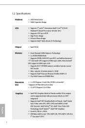
...8226; Gen9 LP, DX11.3, DX12 • HWAEncode/Decode: VP8, HEVC 8b, VP9, HEVC 10b (For 7th Gen Intel® CPU) 2 ECC mode) • Max. 1.2 Specifications Platform CPU • ATX Form Factor • Solid Capacitor design • Supports 7th and 6th Generation Intel® CoreTM i7/i5/i3/ ...2.0 Technology Chipset • Intel® H110 Memory • Dual Channel DDR4 Memory Technology • 2 x DDR4 DIMM Slots • Supports DDR4 2400/2133 non-ECC, un-buffered memory* * 7th Gen Intel® CPU supports DDR4 up to 2400; 6th Gen Intel® CPU supports DDR4 up to 2133. • ...
...8226; Gen9 LP, DX11.3, DX12 • HWAEncode/Decode: VP8, HEVC 8b, VP9, HEVC 10b (For 7th Gen Intel® CPU) 2 ECC mode) • Max. 1.2 Specifications Platform CPU • ATX Form Factor • Solid Capacitor design • Supports 7th and 6th Generation Intel® CoreTM i7/i5/i3/ ...2.0 Technology Chipset • Intel® H110 Memory • Dual Channel DDR4 Memory Technology • 2 x DDR4 DIMM Slots • Supports DDR4 2400/2133 non-ECC, un-buffered memory* * 7th Gen Intel® CPU supports DDR4 up to 2400; 6th Gen Intel® CPU supports DDR4 up to 2133. • ...
User Manual
Page 8
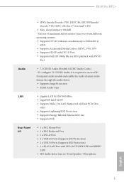
GPU/SWEncode/ Decode: VP9, HEVC 10b (For 6th Gen Intel® CPU) • Max. shared memory 1024MB * The size of maximum shared memory may vary from different operating systems. • Supports DVI-D with LED (ACT/LINK LED ...; 1 x PS/2 Keyboard Port • 1 x DVI-D Port • 4 x USB 2.0 Ports (Supports ESD Protection) • 2 x USB 3.0 Ports (Supports ESD Protection) • 1 x RJ-45 LAN Port with max. H110 Pro BTC+ • HWA Encode/Decode: VP8 , HEVC 8b;
GPU/SWEncode/ Decode: VP9, HEVC 10b (For 6th Gen Intel® CPU) • Max. shared memory 1024MB * The size of maximum shared memory may vary from different operating systems. • Supports DVI-D with LED (ACT/LINK LED ...; 1 x PS/2 Keyboard Port • 1 x DVI-D Port • 4 x USB 2.0 Ports (Supports ESD Protection) • 2 x USB 3.0 Ports (Supports ESD Protection) • 1 x RJ-45 LAN Port with max. H110 Pro BTC+ • HWA Encode/Decode: VP8 , HEVC 8b;
User Manual
Page 9
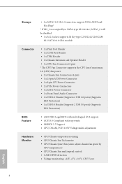
... 6.0 Gb/s module Connector • 1 x Print Port Header • 1 x COM Port Header • 1 x TPM Header • 1 x Chassis Intrusion and Speaker Header • 1 x CPU Fan Connector (4-pin) * The CPU Fan Connector supports the CPU fan of maximum 1A (12W) fan power. • 2 x Chassis Fan Connectors (4-pin) • 1 x 24 pin ATX Power Connector • 1 x 8 pin 12V...
... 6.0 Gb/s module Connector • 1 x Print Port Header • 1 x COM Port Header • 1 x TPM Header • 1 x Chassis Intrusion and Speaker Header • 1 x CPU Fan Connector (4-pin) * The CPU Fan Connector supports the CPU fan of maximum 1A (12W) fan power. • 2 x Chassis Fan Connectors (4-pin) • 1 x 24 pin ATX Power Connector • 1 x 8 pin 12V...
User Manual
Page 10
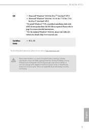
... 34 or more detailed instructions. * For the updated Windows® 10 driver, please visit ASRock's website for possible damage caused by overclocking. We are not responsible for details: http://www.asrock.com • FCC, CE * For detailed product information, please visit our website: http://... using third-party overclocking tools. Please refer to the components and devices of your own risk and expense. H110 Pro BTC+ OS Certifications • Microsoft® Windows® 10 64-bit (For 7th Gen Intel® CPU) • Microsoft® Windows® 10 64-bit / 8.1 64-bit / 7 32-bit ...
... 34 or more detailed instructions. * For the updated Windows® 10 driver, please visit ASRock's website for possible damage caused by overclocking. We are not responsible for details: http://www.asrock.com • FCC, CE * For detailed product information, please visit our website: http://... using third-party overclocking tools. Please refer to the components and devices of your own risk and expense. H110 Pro BTC+ OS Certifications • Microsoft® Windows® 10 64-bit (For 7th Gen Intel® CPU) • Microsoft® Windows® 10 64-bit / 8.1 64-bit / 7 32-bit ...
User Manual
Page 16
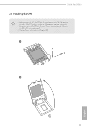
Unplug all power cables before installing the CPU. 1 A B 2 11 English Otherwise, the CPU will be seriously damaged. 2. Do not force to insert the CPU into the socket, please check if the PnP cap is on the socket, if the CPU surface is found. H110 Pro BTC+ 2.1 Installing the CPU 1. Before you insert the 1151-Pin CPU into the socket if above situation is unclean, or if there are any bent pins in the socket.
Unplug all power cables before installing the CPU. 1 A B 2 11 English Otherwise, the CPU will be seriously damaged. 2. Do not force to insert the CPU into the socket, please check if the PnP cap is on the socket, if the CPU surface is found. H110 Pro BTC+ 2.1 Installing the CPU 1. Before you insert the 1151-Pin CPU into the socket if above situation is unclean, or if there are any bent pins in the socket.
User Manual
Page 19
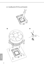
2.2 Installing the CPU Fan and Heatsink 1 2 CPU_FAN English 14
2.2 Installing the CPU Fan and Heatsink 1 2 CPU_FAN English 14
User Manual
Page 26
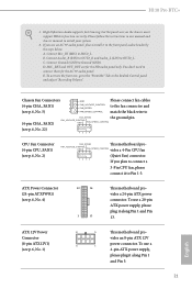
...connect them for the HD audio panel only. C. To use a 20-pin ATX power supply, please plug it to install your system. 2. H110 Pro BTC+ 1. Connect Mic_IN (MIC) to Ground (GND). D. ATX Power Connector (24-pin ATXPWR1) (see p.6, No. 5) GND FAN_VOLTAGE_CONTROL FAN_SPEED ...wire to Pin 1-3. Connect Ground (GND) to MIC2_L. MIC_RET and OUT_RET are for the AC'97 audio panel. FAN_VOLTAGE_CONTROL GND FAN_SPEED_CONTROL vides a 4-Pin CPU fan (Quiet Fan) connector. vides an 8-pin ATX 12V 4 1 power connector. Chassis Fan Connectors (4-pin CHA_FAN1) (see p.6, No. 4) ...
...connect them for the HD audio panel only. C. To use a 20-pin ATX power supply, please plug it to install your system. 2. H110 Pro BTC+ 1. Connect Mic_IN (MIC) to Ground (GND). D. ATX Power Connector (24-pin ATXPWR1) (see p.6, No. 5) GND FAN_VOLTAGE_CONTROL FAN_SPEED ...wire to Pin 1-3. Connect Ground (GND) to MIC2_L. MIC_RET and OUT_RET are for the AC'97 audio panel. FAN_VOLTAGE_CONTROL GND FAN_SPEED_CONTROL vides a 4-Pin CPU fan (Quiet Fan) connector. vides an 8-pin ATX 12V 4 1 power connector. Chassis Fan Connectors (4-pin CHA_FAN1) (see p.6, No. 4) ...
User Manual
Page 45
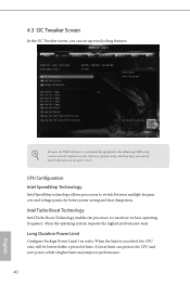
Because the UEFI software is exceeded, the CPU ratio will be lowered after a period of time. CPU Configuration Intel SpeedStep Technology Intel SpeedStep technology allows processors to run above its base operating frequency when the operating system requests the highest performance state. ... the processor to switch between multiple frequencies and voltage points for reference purpose only, and they may not exactly match what you can protect the CPU and save power, while a higher limit may improve performance. 40 English 4.3 OC Tweaker Screen In the OC Tweaker screen, you see on your...
Because the UEFI software is exceeded, the CPU ratio will be lowered after a period of time. CPU Configuration Intel SpeedStep Technology Intel SpeedStep technology allows processors to run above its base operating frequency when the operating system requests the highest performance state. ... the processor to switch between multiple frequencies and voltage points for reference purpose only, and they may not exactly match what you can protect the CPU and save power, while a higher limit may improve performance. 40 English 4.3 OC Tweaker Screen In the OC Tweaker screen, you see on your...
User Manual
Page 46
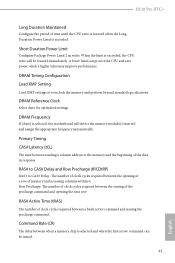
... next row. When the limit is selected, the motherboard will be issued. 41 English DRAM Frequency If [Auto] is exceeded, the CPU ratio will detect the memory module(s) inserted and assign the appropriate frequency automatically. DRAM Timing Configuration Load XMP Setting Load XMP settings to ...the issuing of the precharge command and opening of a row of memory and accessing columns within it. H110 Pro BTC+ Long Duration Maintained Configure the period of time until the CPU ratio is lowered when the Long Duration Power Limit is selected and when the first active command can ...
... next row. When the limit is selected, the motherboard will be issued. 41 English DRAM Frequency If [Auto] is exceeded, the CPU ratio will detect the memory module(s) inserted and assign the appropriate frequency automatically. DRAM Timing Configuration Load XMP Setting Load XMP settings to ...the issuing of the precharge command and opening of a row of memory and accessing columns within it. H110 Pro BTC+ Long Duration Maintained Configure the period of time until the CPU ratio is lowered when the Long Duration Power Limit is selected and when the first active command can ...
User Manual
Page 53
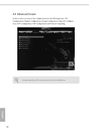
4.4 Advanced Screen In this section may set the configurations for the following items: CPU Configuration, Chipset Configuration, Storage Configuration, Super IO Configuration, ACPI Configuration, USB Configuration and Trusted Computing. Setting wrong values in this section, you may cause the system to malfunction. 48 English
4.4 Advanced Screen In this section may set the configurations for the following items: CPU Configuration, Chipset Configuration, Storage Configuration, Super IO Configuration, ACPI Configuration, USB Configuration and Trusted Computing. Setting wrong values in this section, you may cause the system to malfunction. 48 English

User Manual
Page 54
... in each processor package. Package C State Support Enable CPU, PCIe, Memory, Graphics C State Support for lower power consumption. CPU C3 State Support Enable C3 sleep state for power saving. 49 English 4.4.1 CPU Configuration H110 Pro BTC+ Active Processor Cores Select the number of cores to ...keep C3, C6 and C7 all enabled for lower power consumption. CPU C6 State Support Enable...
... in each processor package. Package C State Support Enable CPU, PCIe, Memory, Graphics C State Support for lower power consumption. CPU C3 State Support Enable C3 sleep state for power saving. 49 English 4.4.1 CPU Configuration H110 Pro BTC+ Active Processor Cores Select the number of cores to ...keep C3, C6 and C7 all enabled for lower power consumption. CPU C6 State Support Enable...
User Manual
Page 55
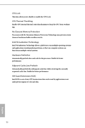
... subsequent cache line while retrieving the currently requested cache line. SW Guard Extensions (SGX) Intel SGX is a set of new CPU instructions that one computer system can be used by applications to set aside private regions of malicious buffer overflow attacks. CFG Lock... This item allows you to keep the CPU from overheating. Intel Virtualization Technology Intel Virtualization Technology allows a platform to run multiple operating systems and applications in independent partitions, ...
... subsequent cache line while retrieving the currently requested cache line. SW Guard Extensions (SGX) Intel SGX is a set of new CPU instructions that one computer system can be used by applications to set aside private regions of malicious buffer overflow attacks. CFG Lock... This item allows you to keep the CPU from overheating. Intel Virtualization Technology Intel Virtualization Technology allows a platform to run multiple operating systems and applications in independent partitions, ...
User Manual
Page 57
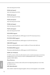
... the link speed for PCIE4. IGPU Multi-Monitor Select disable to PIROI-PIROX. DMI ASPM Support This option enables/disables the control of ASPM on CPU side of memory that is used to route the interrupts it receives from peripheral buses to the integrated graphics processor when the system boots up.... PCIE7 Link Speed Select the link speed for PCIE2. Select the link speed for PCIE7. PCIE5 Link Speed Select the link speed for all CPU downstream devices.
... the link speed for PCIE4. IGPU Multi-Monitor Select disable to PIROI-PIROX. DMI ASPM Support This option enables/disables the control of ASPM on CPU side of memory that is used to route the interrupts it receives from peripheral buses to the integrated graphics processor when the system boots up.... PCIE7 Link Speed Select the link speed for PCIE2. Select the link speed for PCIE7. PCIE5 Link Speed Select the link speed for all CPU downstream devices.
User Manual
Page 66
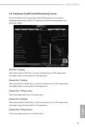
...a fan mode for Chassis Fan 2, or choose Customize to set 5 CPU temperatures and assign a respective fan speed for Chassis Fan 1. CPU Fan 1 Setting Select a fan mode for CPU Fan 1, or choose Customize to set 5 CPU temperatures and assign a respective fan speed for each temperature. Chassis Fan... of the hardware on your system, including the parameters of the CPU temperature, motherboard temperature, fan speed and voltage. H110 Pro BTC+ 4.6 Hardware Health Event Monitoring Screen This section allows you to set 5 CPU temperatures and assign a respective fan speed for Chassis Fan 2. 61...
...a fan mode for Chassis Fan 2, or choose Customize to set 5 CPU temperatures and assign a respective fan speed for Chassis Fan 1. CPU Fan 1 Setting Select a fan mode for CPU Fan 1, or choose Customize to set 5 CPU temperatures and assign a respective fan speed for each temperature. Chassis Fan... of the hardware on your system, including the parameters of the CPU temperature, motherboard temperature, fan speed and voltage. H110 Pro BTC+ 4.6 Hardware Health Event Monitoring Screen This section allows you to set 5 CPU temperatures and assign a respective fan speed for Chassis Fan 2. 61...


