Mining System Installation Guide
Page 1
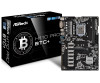
...-series/radeon-rx-470 If the system uses eight RX470 and five GTX1060, the total sum including other components is recommended) 7. Nvidia GTX1060: It requires 120W power for this example is at least 2400W (Depends on our Youtube channel: https://www.youtube.com/watch?time_continue=3&v=c2EDN7xyjZ4 Page 1 ASRock H110 Pro BTC+ mining system Installation Guide Configuration: 1. ASRock H110 Pro BTC+ motherboard 2. 13 x PCIe riser kit 3. 13 x AMD / 8 x AMD + 5 x NVIDIA graphic cards...
...-series/radeon-rx-470 If the system uses eight RX470 and five GTX1060, the total sum including other components is recommended) 7. Nvidia GTX1060: It requires 120W power for this example is at least 2400W (Depends on our Youtube channel: https://www.youtube.com/watch?time_continue=3&v=c2EDN7xyjZ4 Page 1 ASRock H110 Pro BTC+ mining system Installation Guide Configuration: 1. ASRock H110 Pro BTC+ motherboard 2. 13 x PCIe riser kit 3. 13 x AMD / 8 x AMD + 5 x NVIDIA graphic cards...
User Manual
Page 4
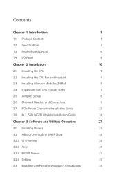
... I/O Panel 8 Chapter 2 Installation 10 2.1 Installing the CPU 11 2.2 Installing the CPU Fan and Heatsink 14 2.3 Installing Memory Modules (DIMM) 15 2.4 Expansion Slots (PCI Express Slots) 17 2.5 Jumpers Setup 18 2.6 Onboard Headers and Connectors 19 2.7 PCIe Power Connector Installation Guide 23 2.8 M.2_SSD (NGFF) Module Installation Guide 24 Chapter 3 Software and Utilities Operation 27 3.1 Installing Drivers 27 3.2 ASRock Live Update & APP Shop 28 3.2.1 UI Overview 28 3.2.2 Apps 29 3.2.3 BIOS & Drivers 32 3.2.4 Setting 33 3.3 Enabling USB Ports for Windows...
... I/O Panel 8 Chapter 2 Installation 10 2.1 Installing the CPU 11 2.2 Installing the CPU Fan and Heatsink 14 2.3 Installing Memory Modules (DIMM) 15 2.4 Expansion Slots (PCI Express Slots) 17 2.5 Jumpers Setup 18 2.6 Onboard Headers and Connectors 19 2.7 PCIe Power Connector Installation Guide 23 2.8 M.2_SSD (NGFF) Module Installation Guide 24 Chapter 3 Software and Utilities Operation 27 3.1 Installing Drivers 27 3.2 ASRock Live Update & APP Shop 28 3.2.1 UI Overview 28 3.2.2 Apps 29 3.2.3 BIOS & Drivers 32 3.2.4 Setting 33 3.3 Enabling USB Ports for Windows...
User Manual
Page 6
... the configuration guide of the software and utilities. In this documentation occur, the updated version will be available on ASRock's website as well. ASRock website http://www.asrock.com. 1.1 Package Contents • ASRock H110 Pro BTC+ Motherboard (ATX Form Factor) • ASRock H110 Pro BTC+ Quick Installation Guide • ASRock H110 Pro BTC+ Support CD • 1 x I/O Panel Shield • 2 x Serial ATA (SATA) Data Cables (Optional) • 1 x Screw for specific information about the model you for purchasing ASRock H110 Pro BTC+ motherboard, a reliable motherboard produced...
... the configuration guide of the software and utilities. In this documentation occur, the updated version will be available on ASRock's website as well. ASRock website http://www.asrock.com. 1.1 Package Contents • ASRock H110 Pro BTC+ Motherboard (ATX Form Factor) • ASRock H110 Pro BTC+ Quick Installation Guide • ASRock H110 Pro BTC+ Support CD • 1 x I/O Panel Shield • 2 x Serial ATA (SATA) Data Cables (Optional) • 1 x Screw for specific information about the model you for purchasing ASRock H110 Pro BTC+ motherboard, a reliable motherboard produced...
User Manual
Page 8
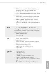
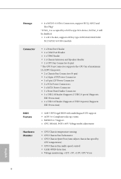
...; Supports PXE Rear Panel I/O • 1 x PS/2 Mouse Port • 1 x PS/2 Keyboard Port • 1 x DVI-D Port • 4 x USB 2.0 Ports (Supports ESD Protection) • 2 x USB 3.0 Ports (Supports ESD Protection) • 1 x RJ-45 LAN Port with max. H110 Pro BTC+ • HWA Encode/Decode: VP8 , HEVC 8b; shared memory 1024MB * The size of maximum shared memory may vary from different operating systems. • Supports DVI-D with LED (ACT/LINK LED and SPEED LED) • HD Audio Jacks: Line in / Front Speaker...
...; Supports PXE Rear Panel I/O • 1 x PS/2 Mouse Port • 1 x PS/2 Keyboard Port • 1 x DVI-D Port • 4 x USB 2.0 Ports (Supports ESD Protection) • 2 x USB 3.0 Ports (Supports ESD Protection) • 1 x RJ-45 LAN Port with max. H110 Pro BTC+ • HWA Encode/Decode: VP8 , HEVC 8b; shared memory 1024MB * The size of maximum shared memory may vary from different operating systems. • Supports DVI-D with LED (ACT/LINK LED and SPEED LED) • HD Audio Jacks: Line in / Front Speaker...
User Manual
Page 9
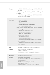
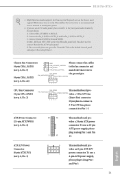
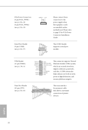
...1 x CPU Fan Connector (4-pin) * The CPU Fan Connector supports the CPU fan of maximum 1A (12W) fan power. • 2 x Chassis Fan Connectors (4-pin) • 1 x 24 pin ATX Power Connector • 1 x 8 pin 12V Power Connector • 2 x PCIe Power Connectors • 1 x SATA Power Connector • 1 x Front Panel Audio Connector • 1 x USB 2.0 Header (Supports 2 USB 2.0 ports) (Supports ESD Protection) • 1 x USB 3.0 Header (Supports 2 USB 3.0 ports) (Supports ESD Protection) BIOS Feature • AMI UEFI Legal BIOS with multilingual GUI support • ACPI 5.0 Compliant wake up...
...1 x CPU Fan Connector (4-pin) * The CPU Fan Connector supports the CPU fan of maximum 1A (12W) fan power. • 2 x Chassis Fan Connectors (4-pin) • 1 x 24 pin ATX Power Connector • 1 x 8 pin 12V Power Connector • 2 x PCIe Power Connectors • 1 x SATA Power Connector • 1 x Front Panel Audio Connector • 1 x USB 2.0 Header (Supports 2 USB 2.0 ports) (Supports ESD Protection) • 1 x USB 3.0 Header (Supports 2 USB 3.0 ports) (Supports ESD Protection) BIOS Feature • AMI UEFI Legal BIOS with multilingual GUI support • ACPI 5.0 Compliant wake up...
User Manual
Page 22
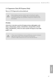
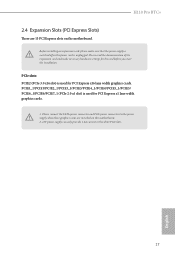
.... PCIe slots: PCIE2 (PCIe 3.0 x16 slot) is used for the card before you start the installation. PCIE1_1/PCIE1/PCIE2_1/PCIE3_1/PCIE3/PCIE4_1/PCIE4/PCIE5_1/PCIE5/ PCIE6_1/PCIE6/PCIE7_1 (PCIe 2.0 x1 slot) is used for PCI Express x1 lane width graphics cards. 1. Please connect the SATA power connector and PCIe power connectors to the power supply when three graphics cards are 13 PCI Express slots on this motherboard. 2. 12V power supply can only provide 1.2A current in the white PCIe slots. 17 English H110 Pro BTC+ 2.4 Expansion Slots (PCI Express Slots) There...
.... PCIe slots: PCIE2 (PCIe 3.0 x16 slot) is used for the card before you start the installation. PCIE1_1/PCIE1/PCIE2_1/PCIE3_1/PCIE3/PCIE4_1/PCIE4/PCIE5_1/PCIE5/ PCIE6_1/PCIE6/PCIE7_1 (PCIe 2.0 x1 slot) is used for PCI Express x1 lane width graphics cards. 1. Please connect the SATA power connector and PCIe power connectors to the power supply when three graphics cards are 13 PCI Express slots on this motherboard. 2. 12V power supply can only provide 1.2A current in the white PCIe slots. 17 English H110 Pro BTC+ 2.4 Expansion Slots (PCI Express Slots) There...
User Manual
Page 24
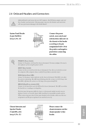
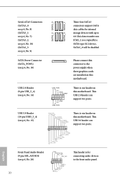
... mainly consists of power switch, reset switch, power LED, hard drive activity LED, speaker and etc. When connecting your system using the power switch. System Panel Header (9-pin PANEL1) (see p.6, No. 11) SPEAKER DUMMY DUMMY +5V 1 SIGNAL GND DUMMY Please connect the chassis intrusion and the chassis speaker to perform a normal restart. Note the positive and negative pins before connecting the cables. Placing jumper caps over these headers and connectors. The LED is on the chassis front panel. The front panel design may configure...
... mainly consists of power switch, reset switch, power LED, hard drive activity LED, speaker and etc. When connecting your system using the power switch. System Panel Header (9-pin PANEL1) (see p.6, No. 11) SPEAKER DUMMY DUMMY +5V 1 SIGNAL GND DUMMY Please connect the chassis intrusion and the chassis speaker to perform a normal restart. Note the positive and negative pins before connecting the cables. Placing jumper caps over these headers and connectors. The LED is on the chassis front panel. The front panel design may configure...
User Manual
Page 25
...+ IntA_P_DGND IntA_P_SSTX+ IntA_P_SSTXGND IntA_P_SSRX+ IntA_P_SSRXVbus There is one header on this motherboard. This USB 2.0 header can support two ports. 1 Vbus IntA_P_SSRXIntA_P_SSRX+ GND IntA_P_SSTXIntA_P_SSTX+ GND IntA_P_DIntA_P_D+ ID English Front Panel Audio Header (9-pin HD_AUDIO1) GND PRESENCE# MIC_RET OUT_RET This header is occupied by a SATA-type M.2 device, SATA3_0 will be disabled. If M2_1 is for internal storage devices with up to the power supply when three graphics cards are installed on this motherboard. This USB 3.0 header can support two ports.
...+ IntA_P_DGND IntA_P_SSTX+ IntA_P_SSTXGND IntA_P_SSRX+ IntA_P_SSRXVbus There is one header on this motherboard. This USB 2.0 header can support two ports. 1 Vbus IntA_P_SSRXIntA_P_SSRX+ GND IntA_P_SSTXIntA_P_SSTX+ GND IntA_P_DIntA_P_D+ ID English Front Panel Audio Header (9-pin HD_AUDIO1) GND PRESENCE# MIC_RET OUT_RET This header is occupied by a SATA-type M.2 device, SATA3_0 will be disabled. If M2_1 is for internal storage devices with up to the power supply when three graphics cards are installed on this motherboard. This USB 3.0 header can support two ports.
User Manual
Page 26
... ground pin. E. To use a 20-pin ATX power supply, please plug it along Pin 1 and Pin 13. If you plan to connect a 3-Pin CPU fan, please connect it to connect them for the HD audio panel only. To use an AC'97 audio panel, please install it to Pin 1-3. FAN_VOLTAGE_CONTROL GND FAN_SPEED_CONTROL vides a 4-Pin CPU fan (Quiet Fan) connector. ATX Power Connector (24-pin ATXPWR1) (see p.6, No. 1) 8 5 This motherboard pro- B. D. You don't need to the front panel audio header by the steps below: A. C. H110 Pro BTC+ 1. Chassis Fan Connectors (4-pin...
... ground pin. E. To use a 20-pin ATX power supply, please plug it along Pin 1 and Pin 13. If you plan to connect a 3-Pin CPU fan, please connect it to connect them for the HD audio panel only. To use an AC'97 audio panel, please install it to Pin 1-3. FAN_VOLTAGE_CONTROL GND FAN_SPEED_CONTROL vides a 4-Pin CPU fan (Quiet Fan) connector. ATX Power Connector (24-pin ATXPWR1) (see p.6, No. 1) 8 5 This motherboard pro- B. D. You don't need to the front panel audio header by the steps below: A. C. H110 Pro BTC+ 1. Chassis Fan Connectors (4-pin...
User Manual
Page 32
... system will be auto-detected and listed on the file "ASRSETUP.EXE" in your CD-ROM drive. If the Main Menu does not appear automatically, locate and double click on the support CD driver page. Therefore, the drivers you install can work properly. Drivers Menu The drivers compatible to install it. The CD automatically displays the Main Menu if "AUTORUN" is enabled in the Support CD to install those required drivers. Click on a specific item then...
... system will be auto-detected and listed on the file "ASRSETUP.EXE" in your CD-ROM drive. If the Main Menu does not appear automatically, locate and double click on the support CD driver page. Therefore, the drivers you install can work properly. Drivers Menu The drivers compatible to install it. The CD automatically displays the Main Menu if "AUTORUN" is enabled in the Support CD to install those required drivers. Click on a specific item then...
User Manual
Page 39
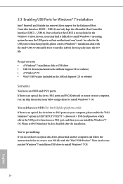
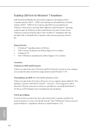
... is an optical disc drive but no PS/2 ports on their support for the USB ports to install Windows® 7 OS. Then use the new patched Windows® 7 installation USB drive to disabled after the installation. 3.3 Enabling USB Ports for Windows® 7 Installation Intel® Braswell and Skylake has removed their motherboard won't work. Please set PS/S Simulator back to install Windows® 7 OS. 34 English In order for the Enhanced Host Controller Interface (EHCI - You...
... is an optical disc drive but no PS/2 ports on their support for the USB ports to install Windows® 7 OS. Then use the new patched Windows® 7 installation USB drive to disabled after the installation. 3.3 Enabling USB Ports for Windows® 7 Installation Intel® Braswell and Skylake has removed their motherboard won't work. Please set PS/S Simulator back to install Windows® 7 OS. 34 English In order for the Enhanced Host Controller Interface (EHCI - You...

User Manual
Page 40
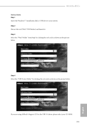
Step 3 Select the "Win7 Folder" from Step1 by clicking the red circle as shown as the picture below . If you are using ASRock's Support CD for the USB 3.0 driver, please select your system. Step 2 Extract the tool (Win7 USB Patcher) and launch it. H110 Pro BTC+ Instructions Step 1 Insert the Windows® 7 installation disk or USB drive to your CD-ROM. 35 English Step 4 Select the "USB Driver Folder" by clicking the red circle as shown as the picture below .
Step 3 Select the "Win7 Folder" from Step1 by clicking the red circle as shown as the picture below . If you are using ASRock's Support CD for the USB 3.0 driver, please select your system. Step 2 Extract the tool (Win7 USB Patcher) and launch it. H110 Pro BTC+ Instructions Step 1 Insert the Windows® 7 installation disk or USB drive to your CD-ROM. 35 English Step 4 Select the "USB Driver Folder" by clicking the red circle as shown as the picture below .
User Manual
Page 60
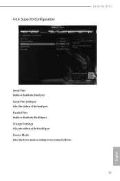
4.4.4 Super IO Configuration H110 Pro BTC+ Serial Port Enable or disable the Serial port. Serial Port Address Select the address of the Parallel port. Change Settings Select the address of the Serial port. Device Mode Select the device mode according to your connected device. 55 English Parallel Port Enable or disable the Parallel port.
4.4.4 Super IO Configuration H110 Pro BTC+ Serial Port Enable or disable the Serial port. Serial Port Address Select the address of the Parallel port. Change Settings Select the address of the Serial port. Device Mode Select the device mode according to your connected device. 55 English Parallel Port Enable or disable the Parallel port.
User Manual
Page 68
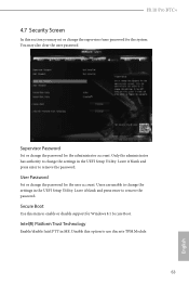
User Password Set or change the password for Windows 8.1 Secure Boot. Intel(R) Platform Trust Technology Enable/disable Intel PTT in the UEFI Setup Utility. Leave it blank and press enter to enable or disable support for the administrator account. Users are unable to remove the password. Disable this option to change the settings in the UEFI Setup Utility. H110 Pro BTC+ 4.7 Security Screen In this item to remove the password. Only the administrator has authority to use discrete TPM Module. 63 English Secure Boot Use this section...
User Password Set or change the password for Windows 8.1 Secure Boot. Intel(R) Platform Trust Technology Enable/disable Intel PTT in the UEFI Setup Utility. Leave it blank and press enter to enable or disable support for the administrator account. Users are unable to remove the password. Disable this option to change the settings in the UEFI Setup Utility. H110 Pro BTC+ 4.7 Security Screen In this item to remove the password. Only the administrator has authority to use discrete TPM Module. 63 English Secure Boot Use this section...
Quick Installation Guide
Page 4
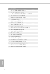
...) 2 CPU Fan Connector (CPU_FAN1) 3 2 x 288-pin DDR4 DIMM Slots (DDR4_A1, DDR4_B1) 4 ATX Power Connector (ATXPWR1) 5 Chassis Fan Connector (CHA_FAN1) 6 TPM Header (TPMS1) 7 SATA3 Connector (SATA3_1) 8 SATA3 Connector (SATA3_0) 9 SATA3 Connector (SATA3_3) 10 SATA3 Connector (SATA3_2) 11 Chassis Intrusion and Speaker Header (SPK_CI1) 12 Clear CMOS Jumper (CLRMOS2) 13 System Panel Header (PANEL1) 14 USB 2.0 Header (USB_5_6) 15 USB 3.0 Header (USB3_3_4) 16 Print Port Header (LPT1) 17 COM Port Header (COM1) 18 SATA Power Connector (SATA_POW1) 19 PCIe Power Connector (PCIE_PWR2) 20 Front Panel Audio...
...) 2 CPU Fan Connector (CPU_FAN1) 3 2 x 288-pin DDR4 DIMM Slots (DDR4_A1, DDR4_B1) 4 ATX Power Connector (ATXPWR1) 5 Chassis Fan Connector (CHA_FAN1) 6 TPM Header (TPMS1) 7 SATA3 Connector (SATA3_1) 8 SATA3 Connector (SATA3_0) 9 SATA3 Connector (SATA3_3) 10 SATA3 Connector (SATA3_2) 11 Chassis Intrusion and Speaker Header (SPK_CI1) 12 Clear CMOS Jumper (CLRMOS2) 13 System Panel Header (PANEL1) 14 USB 2.0 Header (USB_5_6) 15 USB 3.0 Header (USB3_3_4) 16 Print Port Header (LPT1) 17 COM Port Header (COM1) 18 SATA Power Connector (SATA_POW1) 19 PCIe Power Connector (PCIE_PWR2) 20 Front Panel Audio...
Quick Installation Guide
Page 10
...1 x CPU Fan Connector (4-pin) * The CPU Fan Connector supports the CPU fan of maximum 1A (12W) fan power. • 2 x Chassis Fan Connectors (4-pin) • 1 x 24 pin ATX Power Connector • 1 x 8 pin 12V Power Connector • 2 x PCIe Power Connectors • 1 x SATA Power Connector • 1 x Front Panel Audio Connector • 1 x USB 2.0 Header (Supports 2 USB 2.0 ports) (Supports ESD Protection) • 1 x USB 3.0 Header (Supports 2 USB 3.0 ports) (Supports ESD Protection) BIOS Feature • AMI UEFI Legal BIOS with multilingual GUI support • ACPI 5.0 Compliant wake up...
...1 x CPU Fan Connector (4-pin) * The CPU Fan Connector supports the CPU fan of maximum 1A (12W) fan power. • 2 x Chassis Fan Connectors (4-pin) • 1 x 24 pin ATX Power Connector • 1 x 8 pin 12V Power Connector • 2 x PCIe Power Connectors • 1 x SATA Power Connector • 1 x Front Panel Audio Connector • 1 x USB 2.0 Header (Supports 2 USB 2.0 ports) (Supports ESD Protection) • 1 x USB 3.0 Header (Supports 2 USB 3.0 ports) (Supports ESD Protection) BIOS Feature • AMI UEFI Legal BIOS with multilingual GUI support • ACPI 5.0 Compliant wake up...
Quick Installation Guide
Page 19
... necessary hardware settings for the card before you start the installation. Please connect the SATA power connector and PCIe power connectors to the power supply when three graphics cards are 13 PCI Express slots on this motherboard. 2. 12V power supply can only provide 1.2A current in the white PCIe slots. 17 English PCIE1_1/PCIE1/PCIE2_1/PCIE3_1/PCIE3/PCIE4_1/PCIE4/PCIE5_1/PCIE5/ PCIE6_1/PCIE6/PCIE7_1 (PCIe 2.0 x1 slot) is used for PCI Express x1 lane width graphics cards. 1. PCIe slots: PCIE2 (PCIe 3.0 x16 slot) is...
... necessary hardware settings for the card before you start the installation. Please connect the SATA power connector and PCIe power connectors to the power supply when three graphics cards are 13 PCI Express slots on this motherboard. 2. 12V power supply can only provide 1.2A current in the white PCIe slots. 17 English PCIE1_1/PCIE1/PCIE2_1/PCIE3_1/PCIE3/PCIE4_1/PCIE4/PCIE5_1/PCIE5/ PCIE6_1/PCIE6/PCIE7_1 (PCIe 2.0 x1 slot) is used for PCI Express x1 lane width graphics cards. 1. PCIe slots: PCIE2 (PCIe 3.0 x16 slot) is...
Quick Installation Guide
Page 24
... power supply when three graphics cards are installed on this motherboard. Serial Port Header (9-pin COM1) (see p.1, No. 16) AFD# ERROR# PINIT# SLIN# GND 1 SPD7 SPD6 ACK# SPD5 BUSY SPD4 PE SPD3 SLCT SPD2 SPD1 SPD0 STB# This is an interface for PCIe Power Connector Installation Guide. English 22 Print Port Header (25-pin LPT1) (see p.1, No. 17) RRXD1 DDTR#1 DDSR#1 CCTS#1 1 RRI#1 RRTS#1 GND TTXD1 DDCD#1 This COM1 header supports a serial port...
... power supply when three graphics cards are installed on this motherboard. Serial Port Header (9-pin COM1) (see p.1, No. 16) AFD# ERROR# PINIT# SLIN# GND 1 SPD7 SPD6 ACK# SPD5 BUSY SPD4 PE SPD3 SLCT SPD2 SPD1 SPD0 STB# This is an interface for PCIe Power Connector Installation Guide. English 22 Print Port Header (25-pin LPT1) (see p.1, No. 17) RRXD1 DDTR#1 DDSR#1 CCTS#1 1 RRI#1 RRTS#1 GND TTXD1 DDCD#1 This COM1 header supports a serial port...
Quick Installation Guide
Page 144
...; 7 installation disk or USB drive • USB 3.0 drivers (included in the ASRock Support CD or website) • A Windows® PC • Win7 USB Patcher (included in the ASRock Support CD or website) Scenarios You have an ODD and PS/2 ports: If there is an optical disc drive, PS/2 ports and PS/2 Keyboard or mouse on your computer, please enable the "PS/2 Simulator" option in UEFI SETUP UTILITY > Advanced > USB Configuration, which allows the USB port...
...; 7 installation disk or USB drive • USB 3.0 drivers (included in the ASRock Support CD or website) • A Windows® PC • Win7 USB Patcher (included in the ASRock Support CD or website) Scenarios You have an ODD and PS/2 ports: If there is an optical disc drive, PS/2 ports and PS/2 Keyboard or mouse on your computer, please enable the "PS/2 Simulator" option in UEFI SETUP UTILITY > Advanced > USB Configuration, which allows the USB port...
Quick Installation Guide
Page 145
If you are using ASRock's Support CD for the USB 3.0 driver, please select your system. Step 3 Select the "Win7 Folder" from Step1 by clicking the red circle as shown as the picture below . Step 4 Select the "USB Driver Folder" by clicking the red circle as shown as the picture below . Step 2 Extract the tool (Win7 USB Patcher) and launch it. H110 Pro BTC+ Instructions Step 1 Insert the Windows® 7 installation disk or USB drive to your CD-ROM. 143 English
If you are using ASRock's Support CD for the USB 3.0 driver, please select your system. Step 3 Select the "Win7 Folder" from Step1 by clicking the red circle as shown as the picture below . Step 4 Select the "USB Driver Folder" by clicking the red circle as shown as the picture below . Step 2 Extract the tool (Win7 USB Patcher) and launch it. H110 Pro BTC+ Instructions Step 1 Insert the Windows® 7 installation disk or USB drive to your CD-ROM. 143 English


