User Manual
Page 3
... Specifications 5 1.3 Motherboard Layout (GE Pro-HT 7 1.4 Motherboard Layout (GE Pro-M2 8 1.5 ASRock I/OTM (GE Pro-HT / GE Pro-M2 9 2 Installation 10 2.1 Screw Holes 10 2.2 Pre-installation Precautions 10 2.3 CPU Installation 11 2.4 Installation of Heatsink and CPU fan 11 2.5 Installation of Memory Modules (DIMM 12 2.6 Expansion Slots 12 2.7 Jumpers Setup 13 2.8 Connectors 14 3 BIOS Setup 16 3.1 BIOS Setup Utility 16 3.1.1 BIOS Menu Bar 16 3.1.2 Legend Bar 16 3.2 Main Menu 17 3.3 Advanced, Security, Power, Boot, and Exit Menus ...... 19 4 Software Support 20 4.1 Installing...
... Specifications 5 1.3 Motherboard Layout (GE Pro-HT 7 1.4 Motherboard Layout (GE Pro-M2 8 1.5 ASRock I/OTM (GE Pro-HT / GE Pro-M2 9 2 Installation 10 2.1 Screw Holes 10 2.2 Pre-installation Precautions 10 2.3 CPU Installation 11 2.4 Installation of Heatsink and CPU fan 11 2.5 Installation of Memory Modules (DIMM 12 2.6 Expansion Slots 12 2.7 Jumpers Setup 13 2.8 Connectors 14 3 BIOS Setup 16 3.1 BIOS Setup Utility 16 3.1.1 BIOS Menu Bar 16 3.1.2 Legend Bar 16 3.2 Main Menu 17 3.3 Advanced, Security, Power, Boot, and Exit Menus ...... 19 4 Software Support 20 4.1 Installing...

User Manual
Page 4
... endurance. ASRock website http://www.asrock.com 1.1 Package Contents ASRock GE Pro-HT or GE Pro-M2 motherboard (Micro ATX form factor: 9.6" x 7.5", 24.4 x 19.1 cm) ASRock GE Pro-HT / GE Pro-M2 Quick Installation Guide ASRock Intel-SiS Support CD 1 cable for IDE devices (1 x ATA 66 / 100 / 133) 1 cable for purchasing ASRock GE Pro-HT / GE Pro-M2 motherboard, a reliable motherboard produced under ASRock's consistently stringent quality control. You may find the latest memory and CPU support lists on page 21 offers more advanced BIOS setup information. For advanced users' reference...
... endurance. ASRock website http://www.asrock.com 1.1 Package Contents ASRock GE Pro-HT or GE Pro-M2 motherboard (Micro ATX form factor: 9.6" x 7.5", 24.4 x 19.1 cm) ASRock GE Pro-HT / GE Pro-M2 Quick Installation Guide ASRock Intel-SiS Support CD 1 cable for IDE devices (1 x ATA 66 / 100 / 133) 1 cable for purchasing ASRock GE Pro-HT / GE Pro-M2 motherboard, a reliable motherboard produced under ASRock's consistently stringent quality control. You may find the latest memory and CPU support lists on page 21 offers more advanced BIOS setup information. For advanced users' reference...
User Manual
Page 5
... PCI Specification 2.2 AGP slot: 1 universal AGP slot, AGP 2.0 compliant, supports 3.3V / 1.5V, 4X / 2X / 1X AGP card AMR slot: 1 slot, supports ASRock MR card (Optional) USB 2.0: 4 default USB 2.0 ports and 1 extra set of header for 2 additional ASRock I/OTM: USB 2.0 ports upgrade (see CAUTION 4) OS: Microsoft® Windows® 98SE / ME / 2000 / XP compliant 5 ACPI 1.1 compliance wake up to protect CPU life (ASRock U-COP) (see CAUTION 1); Chassis temperature sensing; CPU overheat shutdown to 4 IDE devices Floppy Port: Supports 2 floppy disk drives Audio...
... PCI Specification 2.2 AGP slot: 1 universal AGP slot, AGP 2.0 compliant, supports 3.3V / 1.5V, 4X / 2X / 1X AGP card AMR slot: 1 slot, supports ASRock MR card (Optional) USB 2.0: 4 default USB 2.0 ports and 1 extra set of header for 2 additional ASRock I/OTM: USB 2.0 ports upgrade (see CAUTION 4) OS: Microsoft® Windows® 98SE / ME / 2000 / XP compliant 5 ACPI 1.1 compliance wake up to protect CPU life (ASRock U-COP) (see CAUTION 1); Chassis temperature sensing; CPU overheat shutdown to 4 IDE devices Floppy Port: Supports 2 floppy disk drives Audio...
User Manual
Page 6
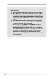
Although GE Pro-HT / GE Pro-M2 offers stepless control, it is detected, the system will also be overclocked proportionally. Please refer to perform over clocking. Please check if the CPU fan on the motherboard functions properly before you install the PC system. 3. Frequencies other clocks, such as PCI clock, AGP clock and Memory clock will automatically shutdown. Power Management for USB 2.0 works fine under Microsoft® Windows® 98/ME/2000. It may...
Although GE Pro-HT / GE Pro-M2 offers stepless control, it is detected, the system will also be overclocked proportionally. Please refer to perform over clocking. Please check if the CPU fan on the motherboard functions properly before you install the PC system. 3. Frequencies other clocks, such as PCI clock, AGP clock and Memory clock will automatically shutdown. Power Management for USB 2.0 works fine under Microsoft® Windows® 98/ME/2000. It may...
User Manual
Page 7
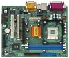
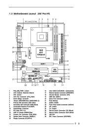
... Graphics Port (AGP1) 10 South Bridge Controller 11 PCI Slots (PCI 1- 2) 12 USB 2.0 Header (USB45, Blue) 13 Chassis Fan Connector (CHA_FAN1) 14 System Panel Connector (PANEL1) 15 Floppy Connector (FLOPPY1) 16 Clear CMOS (CLRCMOS1, solder points) 17 External Speaker Connector (SPEAKER1) 18 Infrared Module Connector (IR1) 19 AMR Slot (AMR1) 20 Serial Port Connector (COM1) 21 Flash Memory 22 AUDIO CODEC 23 Front Panel Audio Connector (AUDIO1) 24 JR1 Jumper 25 JL1 Jumper 26 Internal Audio Connector: CD1 (Black) 27 Internal Audio Connector: AUX1 (White) 28 LAN PHY 29 ATX Power Connector...
... Graphics Port (AGP1) 10 South Bridge Controller 11 PCI Slots (PCI 1- 2) 12 USB 2.0 Header (USB45, Blue) 13 Chassis Fan Connector (CHA_FAN1) 14 System Panel Connector (PANEL1) 15 Floppy Connector (FLOPPY1) 16 Clear CMOS (CLRCMOS1, solder points) 17 External Speaker Connector (SPEAKER1) 18 Infrared Module Connector (IR1) 19 AMR Slot (AMR1) 20 Serial Port Connector (COM1) 21 Flash Memory 22 AUDIO CODEC 23 Front Panel Audio Connector (AUDIO1) 24 JR1 Jumper 25 JL1 Jumper 26 Internal Audio Connector: CD1 (Black) 27 Internal Audio Connector: AUX1 (White) 28 LAN PHY 29 ATX Power Connector...
User Manual
Page 8
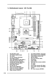
... Graphics Port (AGP1) 10 South Bridge Controller 11 PCI Slots (PCI 1- 2) 12 USB 2.0 Header (USB45, Blue) 13 Chassis Fan Connector (CHA_FAN1) 14 System Panel Connector (PANEL1) 15 Floppy Connector (FLOPPY1) 16 Clear CMOS (CLRCMOS1, solder points) 17 External Speaker Connector (SPEAKER1) 18 Infrared Module Connector (IR1) 19 AMR Slot (AMR1) 20 Serial Port Connector (COM1) 21 Flash Memory 22 AUDIO CODEC 23 Front Panel Audio Connector (AUDIO1) 24 JR1 Jumper 25 JL1 Jumper 26 Internal Audio Connector: CD1 (Black) 27 Internal Audio Connector: AUX1 (White) 28 LAN PHY 29 ATX Power Connector...
... Graphics Port (AGP1) 10 South Bridge Controller 11 PCI Slots (PCI 1- 2) 12 USB 2.0 Header (USB45, Blue) 13 Chassis Fan Connector (CHA_FAN1) 14 System Panel Connector (PANEL1) 15 Floppy Connector (FLOPPY1) 16 Clear CMOS (CLRCMOS1, solder points) 17 External Speaker Connector (SPEAKER1) 18 Infrared Module Connector (IR1) 19 AMR Slot (AMR1) 20 Serial Port Connector (COM1) 21 Flash Memory 22 AUDIO CODEC 23 Front Panel Audio Connector (AUDIO1) 24 JR1 Jumper 25 JL1 Jumper 26 Internal Audio Connector: CD1 (Black) 27 Internal Audio Connector: AUX1 (White) 28 LAN PHY 29 ATX Power Connector...
User Manual
Page 10
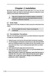
.... Whenever you and damages to the chassis. Unplug the power cord from the power supply. Chapter 2 Installation GE Pro-HT / GE Pro-M2 is detached from the wall socket before you install motherboard components or change any motherboard settings. 1. Make sure to ensure that the power is switched off or the power cord is a Micro ATX form factor (9.6" x 7.5", 24.4 x 19.1 cm) motherboard. To avoid damaging the motherboard components due to static electricity...
.... Whenever you and damages to the chassis. Unplug the power cord from the power supply. Chapter 2 Installation GE Pro-HT / GE Pro-M2 is detached from the wall socket before you install motherboard components or change any motherboard settings. 1. Make sure to ensure that the power is switched off or the power cord is a Micro ATX form factor (9.6" x 7.5", 24.4 x 19.1 cm) motherboard. To avoid damaging the motherboard components due to static electricity...
User Manual
Page 12
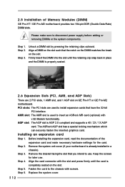
... or GE Pro-M2 motherboard. Step 6. Please make necessary hardware settings for later use . Before installing the expansion card, read the documentation of Memory Modules (DIMM) GE Pro-HT / GE Pro-M2 motherboard provides two 184-pin DDR (Double Data Rate) DIMM slots. Fasten the card to the chassis with the slot and press firmly until the retaining clip snap back in a chassis). 2.5 Installation of the expansion card and make sure to disconnect power supply...
... or GE Pro-M2 motherboard. Step 6. Please make necessary hardware settings for later use . Before installing the expansion card, read the documentation of Memory Modules (DIMM) GE Pro-HT / GE Pro-M2 motherboard provides two 184-pin DDR (Double Data Rate) DIMM slots. Fasten the card to the chassis with the slot and press firmly until the retaining clip snap back in a chassis). 2.5 Installation of the expansion card and make sure to disconnect power supply...
User Manual
Page 16
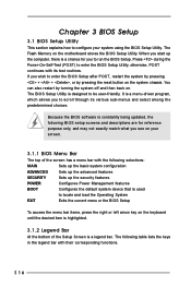
... features POWER Configures Power Management features BOOT Configures the default system device that is used to locate and load the Operating System EXIT Exits the current menu or the BIOS Setup To access the menu bar items, press the right or left arrow key on . The BIOS Setup Utility is designed to be user-friendly. The following table lists the keys in the legend bar with their corresponding functions. 16 The Flash Memory on...
... features POWER Configures Power Management features BOOT Configures the default system device that is used to locate and load the Operating System EXIT Exits the current menu or the BIOS Setup To access the menu bar items, press the right or left arrow key on . The BIOS Setup Utility is designed to be user-friendly. The following table lists the keys in the legend bar with their corresponding functions. 16 The Flash Memory on...
User Manual
Page 17
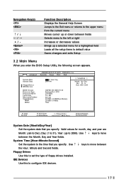
... type of floppy drives installed. IDE Devices Use this to default value Saves changes and exits Setup 3.2 Main Menu When you specify. Floppy Drives Use this to the time that you specify. Main Advanced System Date System Time Floppy Drives IDE Devices BIOS Version Processor Type Processor Speed Cache Size Microcode Update Total Memory DDR1 DDR2 AMIBIOS SETUP UTILITY - VERSION 3.31a Security Power Boot Exit Jul 17 2003 Thu 20:07:40 [ Setup Help ] Month: Jan - System Time [Hour:Minute:Second] Set the system to configure IDE devices. 17 Use keys...
... type of floppy drives installed. IDE Devices Use this to default value Saves changes and exits Setup 3.2 Main Menu When you specify. Floppy Drives Use this to the time that you specify. Main Advanced System Date System Time Floppy Drives IDE Devices BIOS Version Processor Type Processor Speed Cache Size Microcode Update Total Memory DDR1 DDR2 AMIBIOS SETUP UTILITY - VERSION 3.31a Security Power Boot Exit Jul 17 2003 Thu 20:07:40 [ Setup Help ] Month: Jan - System Time [Hour:Minute:Second] Set the system to configure IDE devices. 17 Use keys...

User Manual
Page 19
... transfer. [CD/DVD]: This is used for IDE CD/DVD drives. [ARMD]: This is used to configure the number of cylinders. Refer to the drive documentation to determine the correct value. Block Mode Set the block mode to [On] will enhance hard disk performance by the BIOS based on the drive information you entered. Ultra DMA Mode Ultra DMA capability allows improved transfer speeds and data integrity for compatible IDE devices.
... transfer. [CD/DVD]: This is used for IDE CD/DVD drives. [ARMD]: This is used to configure the number of cylinders. Refer to the drive documentation to determine the correct value. Block Mode Set the block mode to [On] will enhance hard disk performance by the BIOS based on the drive information you entered. Ultra DMA Mode Ultra DMA capability allows improved transfer speeds and data integrity for compatible IDE devices.

User Manual
Page 20
Because motherboard settings and hardware options vary, use the setup procedures in your computer. or you may contact your CD-ROM drive. Click on the file "ASSETUP.EXE" from the BIN folder in the Support CD to display the menus. 4.2.2 Drivers Menu The Drivers Menu shows the available devices drivers if the system detects installed devices. The CD automatically displays the Main Menu if "AUTORUN" is enabled in this demo program, you can...
Because motherboard settings and hardware options vary, use the setup procedures in your computer. or you may contact your CD-ROM drive. Click on the file "ASSETUP.EXE" from the BIN folder in the Support CD to display the menus. 4.2.2 Drivers Menu The Drivers Menu shows the available devices drivers if the system detects installed devices. The CD automatically displays the Main Menu if "AUTORUN" is enabled in this demo program, you can...
User Manual
Page 21
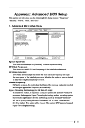
... system with an Intel® Pentium®4 processor that supports Hyper-Threading technology and an operating system that times the front side bus frequency will be [Disabled] for GE Pro-HT only): To enable this technology, such as Microsoft® Windows® XP. This option will equal the core speed of the installed motherboard. Appendix: Advanced BIOS Setup This section will detect the memory module(s) inserted and assigns appropriate...
... system with an Intel® Pentium®4 processor that supports Hyper-Threading technology and an operating system that times the front side bus frequency will be [Disabled] for GE Pro-HT only): To enable this technology, such as Microsoft® Windows® XP. This option will equal the core speed of the installed motherboard. Appendix: Advanced BIOS Setup This section will detect the memory module(s) inserted and assigns appropriate...
User Manual
Page 22
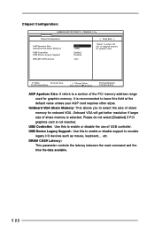
... the time the data available. 22 VERSION 3.31a Chipset Configuration [ Setup Help ] AGP Aperture Size Onboard VGA Share Memory USB Controller USB Device Legacy Support DRAM CAS# Latency 64MB 32MB Enabled Disabled Auto to emulate legacy I/O devices such as mouse, keyboard,... USB Controller: Use this to enable or disable support to select the size of share memory for graphics data. F1:Help Esc:Previous Menu :Select Item +/-:Change Values Enter:Select Sub-Menu F9:Setup Defaults F10:Save & Exit AGP Aperture Size: It refers to leave this...
... the time the data available. 22 VERSION 3.31a Chipset Configuration [ Setup Help ] AGP Aperture Size Onboard VGA Share Memory USB Controller USB Device Legacy Support DRAM CAS# Latency 64MB 32MB Enabled Disabled Auto to emulate legacy I/O devices such as mouse, keyboard,... USB Controller: Use this to enable or disable support to select the size of share memory for graphics data. F1:Help Esc:Previous Menu :Select Item +/-:Change Values Enter:Select Sub-Menu F9:Setup Defaults F10:Save & Exit AGP Aperture Size: It refers to leave this...

User Manual
Page 23
... Serial Port OnBoard Infrared Port OnBoard Parallel Port Parallel Port Mode EPP Version Parallel Port IRQ Parallel Port DMA Channel OnBoard Midi Port Midi IRQ Select OnBoard Game Port OnBoard IDE OnBoard LAN OnBoard AC' 97 Audio OnBoard MC' 97 Modem Auto Auto Disabled Auto ECP+EPP EPP 1.9 Auto N/A Disabled 5 200h Both Enabled Auto Auto to enable or disable floppy drive controller. Resource Configuration: Advanced AMIBIOS SETUP UTILITY - F1:Help Esc:Previous Menu :Select Item +/-:Change Values Enter:Select Sub-Menu F9:Setup Defaults F10:Save & Exit OnBoard FDC: Use...
... Serial Port OnBoard Infrared Port OnBoard Parallel Port Parallel Port Mode EPP Version Parallel Port IRQ Parallel Port DMA Channel OnBoard Midi Port Midi IRQ Select OnBoard Game Port OnBoard IDE OnBoard LAN OnBoard AC' 97 Audio OnBoard MC' 97 Modem Auto Auto Disabled Auto ECP+EPP EPP 1.9 Auto N/A Disabled 5 200h Both Enabled Auto Auto to enable or disable floppy drive controller. Resource Configuration: Advanced AMIBIOS SETUP UTILITY - F1:Help Esc:Previous Menu :Select Item +/-:Change Values Enter:Select Sub-Menu F9:Setup Defaults F10:Save & Exit OnBoard FDC: Use...
User Manual
Page 24
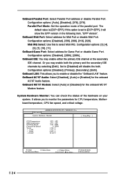
... Version". OnBoard Midi Port: Select address for Game Port or disable Game Port. Midi IRQ Select: Use this option is [ECP+EPP]. Configuration options: [Disabled], [Primary], [Secondary], [Both]. OnBoard LAN: This allows you to monitor the parameters for CPU temperature, Motherboard temperature, CPU fan speed, and critical voltage. Advanced AMIBIOS SETUP UTILITY - OnBoard IDE: You may enable both . The default value is set to enable or disable the "OnBoard LAN" feature. OnBoard Game Port: Select address for Midi Port or disable Midi Port. OnBoard AC'97 Audio...
... Version". OnBoard Midi Port: Select address for Game Port or disable Game Port. Midi IRQ Select: Use this option is [ECP+EPP]. Configuration options: [Disabled], [Primary], [Secondary], [Both]. OnBoard LAN: This allows you to monitor the parameters for CPU temperature, Motherboard temperature, CPU fan speed, and critical voltage. Advanced AMIBIOS SETUP UTILITY - OnBoard IDE: You may enable both . The default value is set to enable or disable the "OnBoard LAN" feature. OnBoard Game Port: Select address for Midi Port or disable Midi Port. OnBoard AC'97 Audio...

User Manual
Page 25
... the Supervisor Password. [Clear]: No password has been set. [Set]: Supervisor password has been set. Set User Password: Press to 6 alphanumeric characters combination. If [Setup] option is selected, the "Password Check" is performed before BIOS setup. 2. Security Setup Menu Main Advanced AMIBIOS SETUP UTILITY - Password Check: Select the check point for "Password Check". Valid password can be a 1 to set the supervisor password. Password Check Setup F1:Help Esc:Exit :Select Item :Select Menu +/-:Change Values Enter:Select Sub-Menu F9:Setup Defaults F10...
... the Supervisor Password. [Clear]: No password has been set. [Set]: Supervisor password has been set. Set User Password: Press to 6 alphanumeric characters combination. If [Setup] option is selected, the "Password Check" is performed before BIOS setup. 2. Security Setup Menu Main Advanced AMIBIOS SETUP UTILITY - Password Check: Select the check point for "Password Check". Valid password can be a 1 to set the supervisor password. Password Check Setup F1:Help Esc:Exit :Select Item :Select Menu +/-:Change Values Enter:Select Sub-Menu F9:Setup Defaults F10...

User Manual
Page 26
... mode. F1:Help Esc:Exit :Select Item :Select Menu +/-:Change Values Enter:Select Sub-Menu F9:Setup Defaults F10:Save & Exit Suspend to RAM (S3): This field allows you desire. 26 It is selected, the AC/Power resumes and the system starts to turn on S3 resume. RTC Alarm Power On: Use this to enable or disable PCI devices to boot up time you to select whether to auto...
... mode. F1:Help Esc:Exit :Select Item :Select Menu +/-:Change Values Enter:Select Sub-Menu F9:Setup Defaults F10:Save & Exit Suspend to RAM (S3): This field allows you desire. 26 It is selected, the AC/Power resumes and the system starts to turn on S3 resume. RTC Alarm Power On: Use this to enable or disable PCI devices to boot up time you to select whether to auto...
User Manual
Page 27
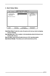
...: If this mode will speed up the boot-up routine by skipping memory retestings. VERSION 3.31a Security Power Boot Exit Quick Boot Mode Boot Up Num-Lock Boot To OS/2 Boot Device Priority Enabled On No [ Setup Help ] to set the boot device priority. 27 F1:Help Esc:Exit :Select Item :Select Menu +/-:Change Values Enter:Select Sub-Menu F9:Setup Defaults F10:Save & Exit Quick Boot Mode: Enable this is enabled, it will enable boot-up . Boot To OS/2: Select...
...: If this mode will speed up the boot-up routine by skipping memory retestings. VERSION 3.31a Security Power Boot Exit Quick Boot Mode Boot Up Num-Lock Boot To OS/2 Boot Device Priority Enabled On No [ Setup Help ] to set the boot device priority. 27 F1:Help Esc:Exit :Select Item :Select Menu +/-:Change Values Enter:Select Sub-Menu F9:Setup Defaults F10:Save & Exit Quick Boot Mode: Enable this is enabled, it will enable boot-up . Boot To OS/2: Select...

User Manual
Page 28
... save the current settings and exit the BIOS SETUP Utility. If you enter the submenu, the message "Load default settings" will appear. 5. Exit Menu Main Advanced AMIBIOS SETUP UTILITY - Load Default Settings: After you press , it will appear. Discard Changes: After you will exit the BIOS SETUP Utility without saving changes" will load the default values for all changes are discarded. 28 VERSION 3.31a Security Power Boot Exit Exit Saving Changes Exit Discarding Changes Load Default Settings Discard Changes [ Enter ] [ Enter ] [ Enter ] [ Enter ] [ Setup Help ] Exits and...
... save the current settings and exit the BIOS SETUP Utility. If you enter the submenu, the message "Load default settings" will appear. 5. Exit Menu Main Advanced AMIBIOS SETUP UTILITY - Load Default Settings: After you press , it will appear. Discard Changes: After you will exit the BIOS SETUP Utility without saving changes" will load the default values for all changes are discarded. 28 VERSION 3.31a Security Power Boot Exit Exit Saving Changes Exit Discarding Changes Load Default Settings Discard Changes [ Enter ] [ Enter ] [ Enter ] [ Enter ] [ Setup Help ] Exits and...


