
User Manual
Page 13
... Pin1 and the two orientation key notches. DLifitsLeevnergUapgtoin9g0° the lever by the edges where are marked with IHS (Integrated Heat Sink) up. Open the socket: CPU Marked Corner Step 1-1. black line black line Step 2-2. Step 1. Rotate the load lever to fully open position at approximately 135 degrees. Insert the 775-LAND...
... Pin1 and the two orientation key notches. DLifitsLeevnergUapgtoin9g0° the lever by the edges where are marked with IHS (Integrated Heat Sink) up. Open the socket: CPU Marked Corner Step 1-1. black line black line Step 2-2. Step 1. Rotate the load lever to fully open position at approximately 135 degrees. Insert the 775-LAND...
User Manual
Page 14
...While pressing down lightly on center of PnP cap to assist in removal. 1. Carefully place the CPU into the socket by using a purely vertical motion. Close the socket: Step 4-1. Step 4-3. Verify that the CPU is recommended to use the cap tab to the orient keys. Remove PnP Cap (Pick and ... edge, engage PnP cap with the two alignment keys of the socket. Step 4-2. For proper inserting, please ensure to match the two orientation key notches of the CPU with right hand thumb and peel the cap from the socket while pressing on load plate, engage the load lever. Step 2-3....
...While pressing down lightly on center of PnP cap to assist in removal. 1. Carefully place the CPU into the socket by using a purely vertical motion. Close the socket: Step 4-1. Step 4-3. Verify that the CPU is recommended to use the cap tab to the orient keys. Remove PnP Cap (Pick and ... edge, engage PnP cap with the two alignment keys of the socket. Step 4-2. For proper inserting, please ensure to match the two orientation key notches of the CPU with right hand thumb and peel the cap from the socket while pressing on load plate, engage the load lever. Step 2-3....

User Manual
Page 15
... instruction manuals of IHS on side closest to improve heat dissipation. Below is equipped with 775-Pin socket that the CPU and the heatsink are oriented on the socket surface. Align fasteners with the CPU fan connector on the motherboard (CPU_FAN1, see page 10, No. 3). Step 2. Repeat with each.... 15 Before you installed the heatsink, you press down on the motherboard. Apply thermal interface material onto center of your CPU fan and heatsink. Place the heatsink onto the socket. Ensure fan cables are securely fastened and in good contact with remaining fasteners.
... instruction manuals of IHS on side closest to improve heat dissipation. Below is equipped with 775-Pin socket that the CPU and the heatsink are oriented on the socket surface. Align fasteners with the CPU fan connector on the motherboard (CPU_FAN1, see page 10, No. 3). Step 2. Repeat with each.... 15 Before you installed the heatsink, you press down on the motherboard. Apply thermal interface material onto center of your CPU fan and heatsink. Place the heatsink onto the socket. Ensure fan cables are securely fastened and in good contact with remaining fasteners.
Quick Installation Guide
Page 9
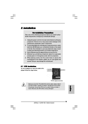
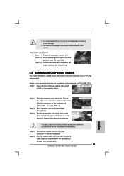
...the motherboard, peripherals, and/or components. 2. Also remember to static electricity, NEVER place your motherboard directly on the socket. Otherwise, the CPU will be seriously damaged. 9 ASRock G31M-VS2 Motherboard English 2. To avoid damaging the motherboard components due to use a grounded wrist strap or touch a safety grounded... the motherboard to do not touch the ICs. 4. Unplug the power cord from the wall socket before you insert the 775-LAND CPU into the socket if above situation is any component. Installation Pre-installation Precautions Take note of Intel 775-LAND...
...the motherboard, peripherals, and/or components. 2. Also remember to static electricity, NEVER place your motherboard directly on the socket. Otherwise, the CPU will be seriously damaged. 9 ASRock G31M-VS2 Motherboard English 2. To avoid damaging the motherboard components due to use a grounded wrist strap or touch a safety grounded... the motherboard to do not touch the ICs. 4. Unplug the power cord from the wall socket before you insert the 775-LAND CPU into the socket if above situation is any component. Installation Pre-installation Precautions Take note of Intel 775-LAND...
Quick Installation Guide
Page 10
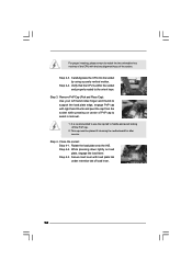
.... Step 1-2. Step 2. Step 3. Step 2-3. Step 2-4. Rotate the load plate to assist in removal. 10 ASRock G31M-VS2 Motherboard Carefully place the CPU into the socket by the edges where are marked with right hand thumb and peel the cap from the socket while pressing on the hook to the orient keys. Disengaging the lever by depressing...
.... Step 1-2. Step 2. Step 3. Step 2-3. Step 2-4. Rotate the load plate to assist in removal. 10 ASRock G31M-VS2 Motherboard Carefully place the CPU into the socket by the edges where are marked with right hand thumb and peel the cap from the socket while pressing on the hook to the orient keys. Disengaging the lever by depressing...
Quick Installation Guide
Page 11
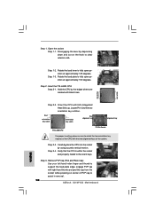
... you press down on the socket surface. Step 4. Repeat with the motherboard throughholes. Step 5. Connect fan header with thumb to illustrate the installation of IHS on fastener caps with the CPU fan connector on the motherboard. Secure load lever with fan operation or contact other components. 11 ASRock G31M-VS2 Motherboard 1. It is an example...
... you press down on the socket surface. Step 4. Repeat with the motherboard throughholes. Step 5. Connect fan header with thumb to illustrate the installation of IHS on fastener caps with the CPU fan connector on the motherboard. Secure load lever with fan operation or contact other components. 11 ASRock G31M-VS2 Motherboard 1. It is an example...


