
User Manual
Page 3
... 16 2.6 Expansion Slots (PCI and PCI Express Slots 17 2.7 Jumpers Setup 18 2.8 Onboard Headers and Connectors 20 2.9 SATAII Hard Disk Setup Guide 23 2.10 Serial ATA (SATA) / Serial ATAII (SATAII) Hard Disks Installation 24 2.11 Driver Installation Guide 24 2.12 Untied Overclocking Technology 24 3 BIOS SETUP UTILITY 25 3.1 Introduction 25 3.1.1 BIOS Menu Bar 25 3.1.2 Navigation Keys 26 3.2 Main Screen 26 3.3 Smart Screen 27 3.4 Advanced Screen 28 3.4.1 CPU Configuration 28 3.4.2 Chipset Configuration 30 3.4.3 ACPI Configuration 33 3.4.4 Storage Configuration 34 3.4.5 PCIPnP...
... 16 2.6 Expansion Slots (PCI and PCI Express Slots 17 2.7 Jumpers Setup 18 2.8 Onboard Headers and Connectors 20 2.9 SATAII Hard Disk Setup Guide 23 2.10 Serial ATA (SATA) / Serial ATAII (SATAII) Hard Disks Installation 24 2.11 Driver Installation Guide 24 2.12 Untied Overclocking Technology 24 3 BIOS SETUP UTILITY 25 3.1 Introduction 25 3.1.1 BIOS Menu Bar 25 3.1.2 Navigation Keys 26 3.2 Main Screen 26 3.3 Smart Screen 27 3.4 Advanced Screen 28 3.4.1 CPU Configuration 28 3.4.2 Chipset Configuration 30 3.4.3 ACPI Configuration 33 3.4.4 Storage Configuration 34 3.4.5 PCIPnP...

User Manual
Page 7
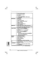
... Energy Saver (see CAUTION 12) - Supports "Plug and Play" - CPU Quiet Fan - Drivers, Utilities, AntiVirus Software (Trial Version), ASRock Software Suite (CyberLink DVD Suite and Creative Sound Blaster X-Fi MB) (OEM and Trial Version) Unique Feature - CPU Frequency Stepless Control (see CAUTION 9) - Front panel audio connector - 2 x USB 2.0 headers (support 4 USB 2.0 ports) (see CAUTION 11) - Chassis Temperature Sensing - FCC, CE - CD in header - ASRock OC DNA (see CAUTION 7) BIOS Feature - 4Mb AMI BIOS - Voltage Monitoring: +12V, +5V, +3.3V, Vcore OS...
... Energy Saver (see CAUTION 12) - Supports "Plug and Play" - CPU Quiet Fan - Drivers, Utilities, AntiVirus Software (Trial Version), ASRock Software Suite (CyberLink DVD Suite and Creative Sound Blaster X-Fi MB) (OEM and Trial Version) Unique Feature - CPU Frequency Stepless Control (see CAUTION 9) - Front panel audio connector - 2 x USB 2.0 headers (support 4 USB 2.0 ports) (see CAUTION 11) - Chassis Temperature Sensing - FCC, CE - CD in header - ASRock OC DNA (see CAUTION 7) BIOS Feature - 4Mb AMI BIOS - Voltage Monitoring: +12V, +5V, +3.3V, Vcore OS...

User Manual
Page 9
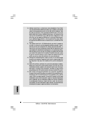
... higher than the recommended CPU bus frequencies may cause the instability of overclocking settings. Although this tool and save the new BIOS file to Intel's suggestion, the EuP ready power supply must use FAT32/16/12 file system. 11. According to your friends! 10. Just launch this motherboard offers stepless control, it is not recommended to access ASRock Instant Flash. Before you install the PC system. 14...
... higher than the recommended CPU bus frequencies may cause the instability of overclocking settings. Although this tool and save the new BIOS file to Intel's suggestion, the EuP ready power supply must use FAT32/16/12 file system. 11. According to your friends! 10. Just launch this motherboard offers stepless control, it is not recommended to access ASRock Instant Flash. Before you install the PC system. 14...

User Manual
Page 10
... 4Mb BIOS Battery RoHS Intel ICH7 7 19 18 17 USB6_7 CHA_FAN1 1 CLRCMOS1 SPEAKER1 1 PCI1 PLED PWRBTN PANEL 1 1 HDLED RESET EuP Ready IDE1 1 USB4_5 SATAII_4 SATAII_3 SATAII_2 SATAII_1 16 15 14 13 12 11 10 9 8 1 PS2_USB_PWR1 Jumper 14 Chassis Speaker Header (SPEAKER 1, White) 2 ATX 12V Connector (ATX12V2) 15 USB 2.0 Header (USB4_5, Blue) 3 CPU Fan Connector (CPU_FAN1) 16 Chassis Fan Connector (CHA_FAN1) 4 ATX Power Connector (ATXPWR1) 17 USB 2.0 Header (USB6_7, Blue) 5 2 x 240-pin DDR2 DIMM Slots 18 Clear CMOS Jumper (CLRCMOS1) (Dual Channel...
... 4Mb BIOS Battery RoHS Intel ICH7 7 19 18 17 USB6_7 CHA_FAN1 1 CLRCMOS1 SPEAKER1 1 PCI1 PLED PWRBTN PANEL 1 1 HDLED RESET EuP Ready IDE1 1 USB4_5 SATAII_4 SATAII_3 SATAII_2 SATAII_1 16 15 14 13 12 11 10 9 8 1 PS2_USB_PWR1 Jumper 14 Chassis Speaker Header (SPEAKER 1, White) 2 ATX 12V Connector (ATX12V2) 15 USB 2.0 Header (USB4_5, Blue) 3 CPU Fan Connector (CPU_FAN1) 16 Chassis Fan Connector (CHA_FAN1) 4 ATX Power Connector (ATXPWR1) 17 USB 2.0 Header (USB6_7, Blue) 5 2 x 240-pin DDR2 DIMM Slots 18 Clear CMOS Jumper (CLRCMOS1) (Dual Channel...

User Manual
Page 21
...BIOS Setup Utility. If you adopt a traditional 20-pin ATX power supply. E. To use the 20-pin ATX power supply, please plug your power supply along with Pin 1 and Pin 13. 24 13 20-Pin ATX Power Supply Installation 12 1 21 Enter Advanced Settings, and then select Chipset Configuration. Set the Front Panel Control option from [Auto] to this motherboard, please connect it can work if you plan to connect the 3-Pin CPU fan to the CPU fan connector on this connector and match the black wire to Pin 1-3. GND +12V CHA_FAN_SPEED Please connect a chassis fan cable to [Enabled...
...BIOS Setup Utility. If you adopt a traditional 20-pin ATX power supply. E. To use the 20-pin ATX power supply, please plug your power supply along with Pin 1 and Pin 13. 24 13 20-Pin ATX Power Supply Installation 12 1 21 Enter Advanced Settings, and then select Chipset Configuration. Set the Front Panel Control option from [Auto] to this motherboard, please connect it can work if you plan to connect the 3-Pin CPU fan to the CPU fan connector on this connector and match the black wire to Pin 1-3. GND +12V CHA_FAN_SPEED Please connect a chassis fan cable to [Enabled...
User Manual
Page 23
.../hdd/support/download.htm The above examples are just for the updates. 23 In order to enable SATAII function, please follow the below SATAII hard disk setup guide. Please visit the vendors' website for your reference. otherwise, your SATAII hard disk may not be the same. 2 . 9 SATAII Hard Disk Setup Guide Before installing SATAII hard disk to your SATAII hard disk to SATAII mode in advance; Some default setting of different vendors, the jumper pin setting...
.../hdd/support/download.htm The above examples are just for the updates. 23 In order to enable SATAII function, please follow the below SATAII hard disk setup guide. Please visit the vendors' website for your reference. otherwise, your SATAII hard disk may not be the same. 2 . 9 SATAII Hard Disk Setup Guide Before installing SATAII hard disk to your SATAII hard disk to SATAII mode in advance; Some default setting of different vendors, the jumper pin setting...

User Manual
Page 24
... and listed on page 8 for internal storage devices. STEP 2: Connect the SATA power cable to install those required drivers. Then, the drivers compatible to the motherboard's SATAII connector. Therefore, the drivers you to the warning on the support CD driver page. Please refer to install the SATA / SATAII hard disks. STEP 3: Connect one end of your optical drive first. You may install SATA / SATAII hard disks on this motherboard for the possible overclocking risk before you enable Untied Overclocking function, please enter "Overclock Mode" option...
... and listed on page 8 for internal storage devices. STEP 2: Connect the SATA power cable to install those required drivers. Then, the drivers compatible to the motherboard's SATAII connector. Therefore, the drivers you to the warning on the support CD driver page. Please refer to install the SATA / SATAII hard disks. STEP 3: Connect one end of your optical drive first. You may install SATA / SATAII hard disks on this motherboard for the possible overclocking risk before you enable Untied Overclocking function, please enter "Overclock Mode" option...
User Manual
Page 29
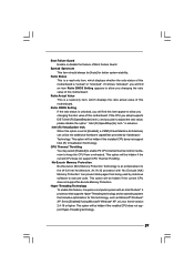
... (NX) Memory Protection" can utilize the additional hardware capabilities provided by malicious software to execute code. Set to adjust the ratio value, please disable the option " Intel (R) SpeedStep(tm) tech." Ratio Actual Value This is "Locked" or "Unlocked". Spread Spectrum This item should always be hidden if the current CPU does not support CPU Thermal Throttling. Boot Failure Guard Enable or disable the feature...
... (NX) Memory Protection" can utilize the additional hardware capabilities provided by malicious software to execute code. Set to adjust the ratio value, please disable the option " Intel (R) SpeedStep(tm) tech." Ratio Actual Value This is "Locked" or "Unlocked". Spread Spectrum This item should always be hidden if the current CPU does not support CPU Thermal Throttling. Boot Failure Guard Enable or disable the feature...
User Manual
Page 30
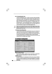
...(tm) tech. The default value is [Auto]. 3.4.2 Chipset Configuration BIOS SETUP UTILITY Advanced Chipset Settings Memory Remap Feature DRAM Frequency DRAM tCL DRAM tRCD DRAM tRP DRAM tRAS [Disabled] [Auto] [Auto] [Auto] [Auto] [Auto] Primary Graphics Adapter Internal Graphics Mode Select DVMT Mode Select DVMT/FIXED Memory [PCI] [Auto] [DVMT Mode] [Maximum DVMT] Onboard HD Audio Front Panel OnBoard Lan [Auto] [Auto] [Enabled] DRAM Voltage [Auto] ENABLE: Allow remapping of memory. +F1 F9 F10 ESC Select Screen Select Item Change Option General Help Load Defaults Save and Exit Exit...
...(tm) tech. The default value is [Auto]. 3.4.2 Chipset Configuration BIOS SETUP UTILITY Advanced Chipset Settings Memory Remap Feature DRAM Frequency DRAM tCL DRAM tRCD DRAM tRP DRAM tRAS [Disabled] [Auto] [Auto] [Auto] [Auto] [Auto] Primary Graphics Adapter Internal Graphics Mode Select DVMT Mode Select DVMT/FIXED Memory [PCI] [Auto] [DVMT Mode] [Maximum DVMT] Onboard HD Audio Front Panel OnBoard Lan [Auto] [Auto] [Enabled] DRAM Voltage [Auto] ENABLE: Allow remapping of memory. +F1 F9 F10 ESC Select Screen Select Item Change Option General Help Load Defaults Save and Exit Exit...
User Manual
Page 31
... mode. Onboard HD Audio Select [Auto], [Enabled] or [Disabled] for the motherboard through efficient memory utilization. Configuration options: [Onboard], [PCI] and [PCI Express]. DVMT Mode Select Use this item if you select [Auto], the onboard VGA will be enabled without the installation of the system memory is plugged. 31 DVMT/FIXED Memory You are [6], [5], [4], [3] and [Auto]. Internal Graphics Mode Select If you set DVMT Mode Select as needed for running graphics applications and is [DVMT Mode]. Configuration options: [3 DRAM Clocks], [4 DRAM Clocks], [5 DRAM Clocks...
... mode. Onboard HD Audio Select [Auto], [Enabled] or [Disabled] for the motherboard through efficient memory utilization. Configuration options: [Onboard], [PCI] and [PCI Express]. DVMT Mode Select Use this item if you select [Auto], the onboard VGA will be enabled without the installation of the system memory is plugged. 31 DVMT/FIXED Memory You are [6], [5], [4], [3] and [Auto]. Internal Graphics Mode Select If you set DVMT Mode Select as needed for running graphics applications and is [DVMT Mode]. Configuration options: [3 DRAM Clocks], [4 DRAM Clocks], [5 DRAM Clocks...
User Manual
Page 36
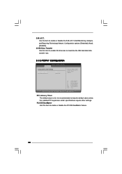
PCI IDE BusMaster Use this item to enable 32-bit access to enable or disable the PCI IDE BusMaster feature. 36 Configuration options: [Disabled], [Auto], [Enabled]. 32-Bit Data Transfer Use this item to maximize the IDE hard disk data transfer rate. 3.4.5 PCIPnP Configuration BIOS SETUP UTILITY Advanced Advanced PCI / PnP Settings PCI Latency Timer PCI IDE BusMaster [32] [Enabled] Value in units of PCI clocks for PCI device latency timer register. +F1 F9 F10 ESC Select Screen Select Item Change Option General Help Load Defaults Save and Exit Exit...
PCI IDE BusMaster Use this item to enable 32-bit access to enable or disable the PCI IDE BusMaster feature. 36 Configuration options: [Disabled], [Auto], [Enabled]. 32-Bit Data Transfer Use this item to maximize the IDE hard disk data transfer rate. 3.4.5 PCIPnP Configuration BIOS SETUP UTILITY Advanced Advanced PCI / PnP Settings PCI Latency Timer PCI IDE BusMaster [32] [Enabled] Value in units of PCI clocks for PCI device latency timer register. +F1 F9 F10 ESC Select Screen Select Item Change Option General Help Load Defaults Save and Exit Exit...
User Manual
Page 38
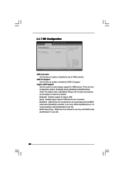
...Enabled] - USB devices are four configuration options: [Enabled], [Auto], [Disabled] and [BIOS Setup Only]. USB devices are connected. [Disabled] - 3.4.7 USB Configuration BIOS SETUP UTILITY Advanced USB Configuration USB Controller USB 2.0 Support Legacy USB Support [Enabled] [Enabled] [Enabled] To enable or disable the onboard USB controllers. +F1 F9 F10 ESC Select Screen Select Item Change Option General Help Load Defaults Save and Exit Exit v02.54 (C) Copyright 1985-2005, American Megatrends, Inc. Enables legacy support if USB devices are not allowed to enter OS. [BIOS Setup...
...Enabled] - USB devices are four configuration options: [Enabled], [Auto], [Disabled] and [BIOS Setup Only]. USB devices are connected. [Disabled] - 3.4.7 USB Configuration BIOS SETUP UTILITY Advanced USB Configuration USB Controller USB 2.0 Support Legacy USB Support [Enabled] [Enabled] [Enabled] To enable or disable the onboard USB controllers. +F1 F9 F10 ESC Select Screen Select Item Change Option General Help Load Defaults Save and Exit Exit v02.54 (C) Copyright 1985-2005, American Megatrends, Inc. Enables legacy support if USB devices are not allowed to enter OS. [BIOS Setup...
User Manual
Page 41
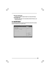
... disable the Boot From Onboard LAN feature. Boot Up Num-Lock If this section, you may also clear it will automatically activate the Numeric Lock function after boot-up. 3.7 Security Screen In this item is set or change the supervisor/user password for the system. BIOS SETUP UTILITY Main Smart Advanced H/W Monitor Boot Security Exit Security Settings Supervisor Password : Not Installed User Password : Not Installed Change Supervisor Password Change User Password Install or Change the password. Select Screen Select Item Enter Change F1 General Help F9 Load Defaults...
... disable the Boot From Onboard LAN feature. Boot Up Num-Lock If this section, you may also clear it will automatically activate the Numeric Lock function after boot-up. 3.7 Security Screen In this item is set or change the supervisor/user password for the system. BIOS SETUP UTILITY Main Smart Advanced H/W Monitor Boot Security Exit Security Settings Supervisor Password : Not Installed User Password : Not Installed Change Supervisor Password Change User Password Install or Change the password. Select Screen Select Item Enter Change F1 General Help F9 Load Defaults...
User Manual
Page 43
... motherboard settings and hardware options vary, use the setup procedures in your CD-ROM drive. Chapter 4 Software Support 4.1 Install Operating System This motherboard supports various Microsoft® Windows® operating systems: 7 / 7 64-bit / VistaTM / VistaTM 64-bit / XP / XP 64-bit. or you need to contact ASRock or want to visit ASRock's website at http://www.asrock.com; Click on the file "ASSETUP.EXE" from the BIN folder in the Support...
... motherboard settings and hardware options vary, use the setup procedures in your CD-ROM drive. Chapter 4 Software Support 4.1 Install Operating System This motherboard supports various Microsoft® Windows® operating systems: 7 / 7 64-bit / VistaTM / VistaTM 64-bit / XP / XP 64-bit. or you need to contact ASRock or want to visit ASRock's website at http://www.asrock.com; Click on the file "ASSETUP.EXE" from the BIN folder in the Support...
Quick Installation Guide
Page 6
... Boot Failure Guard (B.F.G.) Hardware - CPU Fan Tachometer - Microsoft® Windows® 7 / 7 64-bit / VistaTM / VistaTM 64-bit / XP / XP 64-bit compliant Certifications - Front panel audio connector - 2 x USB 2.0 headers (support 4 USB 2.0 ports) (see CAUTION 11) - Supports "Plug and Play" - VCCM Voltage Multi-adjustment - ASRock OC DNA (see CAUTION 7) BIOS Feature - 4Mb AMI BIOS - Chassis Temperature Sensing - CPU Quiet Fan - AMI Legal BIOS - Drivers, Utilities, AntiVirus Software (Trial Version), ASRock Software Suite (CyberLink DVD Suite and Creative Sound...
... Boot Failure Guard (B.F.G.) Hardware - CPU Fan Tachometer - Microsoft® Windows® 7 / 7 64-bit / VistaTM / VistaTM 64-bit / XP / XP 64-bit compliant Certifications - Front panel audio connector - 2 x USB 2.0 headers (support 4 USB 2.0 ports) (see CAUTION 11) - Supports "Plug and Play" - VCCM Voltage Multi-adjustment - ASRock OC DNA (see CAUTION 7) BIOS Feature - 4Mb AMI BIOS - Chassis Temperature Sensing - CPU Quiet Fan - AMI Legal BIOS - Drivers, Utilities, AntiVirus Software (Trial Version), ASRock Software Suite (CyberLink DVD Suite and Creative Sound...
Quick Installation Guide
Page 7
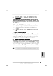
... "User Manual" in the BIOS, applying Untied Overclocking Technology, or using the thirdparty overclocking tools. This motherboard supports Untied Overclocking Technology. Overclocking may be done at your hardware devices to the components and devices of ASRock OC Tuner. We are not responsible for the operation procedures of your system stability, or even cause damage to get the best system performance under Windows® environment. This motherboard supports Dual Channel Memory Technology. Please...
... "User Manual" in the BIOS, applying Untied Overclocking Technology, or using the thirdparty overclocking tools. This motherboard supports Untied Overclocking Technology. Overclocking may be done at your hardware devices to the components and devices of ASRock OC Tuner. We are not responsible for the operation procedures of your system stability, or even cause damage to get the best system performance under Windows® environment. This motherboard supports Dual Channel Memory Technology. Please...
Quick Installation Guide
Page 8
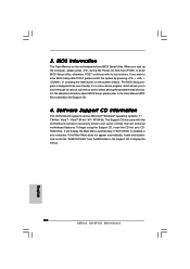
... unplug the power cord, then plug it is higher than the recommended CPU bus frequencies may cause the instability of . Although this utility, you can press key during the POST or press key to BIOS setup menu to define the power consumption for the user to get the same OC settings as a profile and share with the power supply manufacturer for more details. 8 ASRock G31M-VS2 Motherboard English While CPU overheat is...
... unplug the power cord, then plug it is higher than the recommended CPU bus frequencies may cause the instability of . Although this utility, you can press key during the POST or press key to BIOS setup menu to define the power consumption for the user to get the same OC settings as a profile and share with the power supply manufacturer for more details. 8 ASRock G31M-VS2 Motherboard English While CPU overheat is...
Quick Installation Guide
Page 17
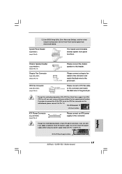
... CPU fan (Quiet Fan) support, the 3-Pin CPU fan still can still work successfully even without the fan speed control function. If you adopt a traditional 20-pin ATX power supply. To use the 20-pin ATX power supply, please plug your power supply along with Pin 1 and Pin 13. 24 13 20-PinATX Power Supply Installation 12 1 17 ASRock G31M-VS2 Motherboard English Set the Front Panel Control option from [Auto] to Pin 1-3. Chassis Speaker Header (4-pin SPEAKER 1) (see p.2 No. 14) Chassis Fan Connector (3-pin CHA_FAN1) (see p.2 No. 3) 1 2 3 4 Please connect a CPU fan cable to the CPU...
... CPU fan (Quiet Fan) support, the 3-Pin CPU fan still can still work successfully even without the fan speed control function. If you adopt a traditional 20-pin ATX power supply. To use the 20-pin ATX power supply, please plug your power supply along with Pin 1 and Pin 13. 24 13 20-PinATX Power Supply Installation 12 1 17 ASRock G31M-VS2 Motherboard English Set the Front Panel Control option from [Auto] to Pin 1-3. Chassis Speaker Header (4-pin SPEAKER 1) (see p.2 No. 14) Chassis Fan Connector (3-pin CHA_FAN1) (see p.2 No. 3) 1 2 3 4 Please connect a CPU fan cable to the CPU...
Quick Installation Guide
Page 19
... mode so that supports Serial ATA (SATA) / Serial ATAII (SATAII) hard disks. STEP 1: Install the SATA / SATAII hard disks into the drive bays of BIOS setup to set the selection from up to bottom side to your system can operate under a more stable overclocking environment. Then, the drivers compatible to install those required drivers. Therefore, the drivers you enable Untied Overclocking function, please enter "Overclock Mode" option of your optical drive first. STEP 2: Connect the SATA power cable to install the SATA / SATAII hard disks. STEP 4: Connect...
... mode so that supports Serial ATA (SATA) / Serial ATAII (SATAII) hard disks. STEP 1: Install the SATA / SATAII hard disks into the drive bays of BIOS setup to set the selection from up to bottom side to your system can operate under a more stable overclocking environment. Then, the drivers compatible to install those required drivers. Therefore, the drivers you enable Untied Overclocking function, please enter "Overclock Mode" option of your optical drive first. STEP 2: Connect the SATA power cable to install the SATA / SATAII hard disks. STEP 4: Connect...
Quick Installation Guide
Page 20
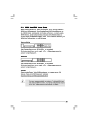
... press during the Power-On-Self-Test (POST) to display the menus. 20 ASRock G31M-VS2 Motherboard English The BIOS Setup program is enabled in your CDROM drive. To begin using the Support CD, insert the CD into your computer. It will enhance motherboard features. For the detailed information about BIOS Setup, please refer to the User Manual (PDF file) contained in the Support CD to enter BIOS Setup utility; 3. If the Main Menu does not appear...
... press during the Power-On-Self-Test (POST) to display the menus. 20 ASRock G31M-VS2 Motherboard English The BIOS Setup program is enabled in your CDROM drive. To begin using the Support CD, insert the CD into your computer. It will enhance motherboard features. For the detailed information about BIOS Setup, please refer to the User Manual (PDF file) contained in the Support CD to enter BIOS Setup utility; 3. If the Main Menu does not appear...


