
User Manual
Page 3
... 3.3 Smart Screen 27 3.4 Advanced Screen 28 3.4.1 CPU Configuration 28 3.4.2 Chipset Configuration 30 3.4.3 ACPI Configuration 33 3.4.4 Storage Configuration 34 3.4.5 PCIPnP Configuration 36 3.4.6 Super IO Configuration 37 3.4.7 USB Configuration 38 3.5 Hardware Health Event Monitoring Screen 39 3.6 Boot Screen 40 3.6.1 Boot Settings Configuration 40 3.7 Security Screen 41 3.8 Exit Screen 42 3
... 3.3 Smart Screen 27 3.4 Advanced Screen 28 3.4.1 CPU Configuration 28 3.4.2 Chipset Configuration 30 3.4.3 ACPI Configuration 33 3.4.4 Storage Configuration 34 3.4.5 PCIPnP Configuration 36 3.4.6 Super IO Configuration 37 3.4.7 USB Configuration 38 3.5 Hardware Health Event Monitoring Screen 39 3.6 Boot Screen 40 3.6.1 Boot Settings Configuration 40 3.7 Security Screen 41 3.8 Exit Screen 42 3
User Manual
Page 6
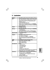
... Wolfdale processors - LGA 775 for RAID and "Hot Plug" functions) (see CAUTION 4) - 1 x PCI Express x16 slot - 1 x PCI slot - Supports EM64T CPU - resolution up to -Use USB 2.0 Ports - 1 x RJ-45 LAN Port with max. CPU/Chassis FAN connector HD Audio Jack: Line in , 22.6 cm x 17.0 cm -
... Wolfdale processors - LGA 775 for RAID and "Hot Plug" functions) (see CAUTION 4) - 1 x PCI Express x16 slot - 1 x PCI slot - Supports EM64T CPU - resolution up to -Use USB 2.0 Ports - 1 x RJ-45 LAN Port with max. CPU/Chassis FAN connector HD Audio Jack: Line in , 22.6 cm x 17.0 cm -

User Manual
Page 7
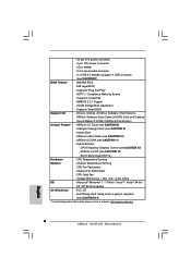
... CAUTION 13) - AMI Legal BIOS - Supports Smart BIOS Support CD - Instant Boot - Front panel audio connector - 2 x USB 2.0 headers (support 4 USB 2.0 ports) (see CAUTION 12) - CPU Frequency Stepless Control (see CAUTION 7) BIOS Feature - 4Mb AMI BIOS - ASRock Instant Flash (see CAUTION 9) - Intelligent Energy Saver (see CAUTION 10) - Supports "Plug and Play" - Microsoft® Windows...
... CAUTION 13) - AMI Legal BIOS - Supports Smart BIOS Support CD - Instant Boot - Front panel audio connector - 2 x USB 2.0 headers (support 4 USB 2.0 ports) (see CAUTION 12) - CPU Frequency Stepless Control (see CAUTION 7) BIOS Feature - 4Mb AMI BIOS - ASRock Instant Flash (see CAUTION 9) - Intelligent Energy Saver (see CAUTION 10) - Supports "Plug and Play" - Microsoft® Windows...

User Manual
Page 8
...such limitation. 5. CAUTION! 1. Before you to surveil your SATAII hard disk drive to read the installation guide of memory modules on page 24 for USB 2.0 works fine under Windows® 7 / VistaTM / XP. For Windows® OS with overclocking, including adjusting the setting in the BIOS, ... on page 16 for the operation procedures of Intelligent Energy Saver. Before installing SATAII hard disk to change. It is a user-friendly ASRock overclocking tool which allows you implement Dual Channel Memory Technology, make sure to SATAII mode. In other words, it is able to SATAII...
...such limitation. 5. CAUTION! 1. Before you to surveil your SATAII hard disk drive to read the installation guide of memory modules on page 24 for USB 2.0 works fine under Windows® 7 / VistaTM / XP. For Windows® OS with overclocking, including adjusting the setting in the BIOS, ... on page 16 for the operation procedures of Intelligent Energy Saver. Before installing SATAII hard disk to change. It is a user-friendly ASRock overclocking tool which allows you implement Dual Channel Memory Technology, make sure to SATAII mode. In other words, it is able to SATAII...

User Manual
Page 9
...14. The software name itself - 10. Although this utility, you what it back again. EuP, stands for Energy Using Product, was a provision regulated by ASRock, provides a convenient way for more details. 9 To meet the standard of the system or damage the CPU. 13. With this motherboard offers stepless control, ... shutdown. Please be noticed that the OC profile can save the new BIOS file to your USB flash drive, floppy disk or hard drive, then you can only be noted that the USB flash drive or hard drive must meet EuP standard, an EuP ready motherboard and an EuP ...
...14. The software name itself - 10. Although this utility, you what it back again. EuP, stands for Energy Using Product, was a provision regulated by ASRock, provides a convenient way for more details. 9 To meet the standard of the system or damage the CPU. 13. With this motherboard offers stepless control, ... shutdown. Please be noticed that the OC profile can save the new BIOS file to your USB flash drive, floppy disk or hard drive, then you can only be noted that the USB flash drive or hard drive must meet EuP standard, an EuP ready motherboard and an EuP ...

User Manual
Page 10
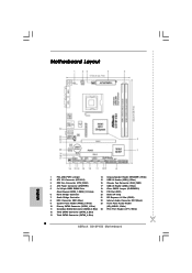
...64 bit, 240-piFnSmBod8ul0e)0 DDRII_2 (64 bit, 240-piFnSmBod8ul0e)0 FSB1333 DDR2 800 Dual Channel VGA1 G31M-VS2 USB 2.0 T: USB2 B: USB3 1 Top: Line In Center: Line Out Bottom: Mic In 24 USB 2.0 T: USB0 B: USB1 Top: RJ-45 Super IO Intel G31 Chipset LAN 23 HD_AUDIO1 PHY...PS2_USB_PWR1 Jumper 14 Chassis Speaker Header (SPEAKER 1, White) 2 ATX 12V Connector (ATX12V2) 15 USB 2.0 Header (USB4_5, Blue) 3 CPU Fan Connector (CPU_FAN1) 16 Chassis Fan Connector (CHA_FAN1) 4 ATX Power Connector (ATXPWR1) 17 USB 2.0 Header (USB6_7, Blue) 5 2 x 240-pin DDR2 DIMM Slots 18 Clear CMOS ...
...64 bit, 240-piFnSmBod8ul0e)0 DDRII_2 (64 bit, 240-piFnSmBod8ul0e)0 FSB1333 DDR2 800 Dual Channel VGA1 G31M-VS2 USB 2.0 T: USB2 B: USB3 1 Top: Line In Center: Line Out Bottom: Mic In 24 USB 2.0 T: USB0 B: USB1 Top: RJ-45 Super IO Intel G31 Chipset LAN 23 HD_AUDIO1 PHY...PS2_USB_PWR1 Jumper 14 Chassis Speaker Header (SPEAKER 1, White) 2 ATX 12V Connector (ATX12V2) 15 USB 2.0 Header (USB4_5, Blue) 3 CPU Fan Connector (CPU_FAN1) 16 Chassis Fan Connector (CHA_FAN1) 4 ATX Power Connector (ATXPWR1) 17 USB 2.0 Header (USB6_7, Blue) 5 2 x 240-pin DDR2 DIMM Slots 18 Clear CMOS ...
User Manual
Page 11
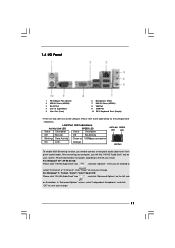
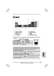
... find "VIA HD Audio Deck" tool on the bottom. After restarting your system. 1.4 I/O Panel 1 PS/2 Mouse Port (Green) 2 USB 2.0 Ports (USB23) 3 RJ-45 Port 4 Line In (Light Blue) 5 Line Out (Lime) 6 Microphone (Pink) 7 USB 2.0 Ports (USB01) 8 VGA Port 9 COM Port 10 PS/2 Keyboard Port (Purple) * There are allowed to select "2 Channel" or...
... find "VIA HD Audio Deck" tool on the bottom. After restarting your system. 1.4 I/O Panel 1 PS/2 Mouse Port (Green) 2 USB 2.0 Ports (USB23) 3 RJ-45 Port 4 Line In (Light Blue) 5 Line Out (Lime) 6 Microphone (Pink) 7 USB 2.0 Ports (USB01) 8 VGA Port 9 COM Port 10 PS/2 Keyboard Port (Purple) * There are allowed to select "2 Channel" or...

User Manual
Page 18
... to short 2 pins on pins, the jumper is "Open". To clear and reset the system parameters to enable +5VSB (standby) for PS/2 +5V +5VSB or USB wake up events. After waiting for 5 seconds. 18 2.7 Jumpers Setup The illustration shows how jumpers are "Short" when jumper cap is "Short". When the jumper...
... to short 2 pins on pins, the jumper is "Open". To clear and reset the system parameters to enable +5VSB (standby) for PS/2 +5V +5VSB or USB wake up events. After waiting for 5 seconds. 18 2.7 Jumpers Setup The illustration shows how jumpers are "Short" when jumper cap is "Short". When the jumper...
User Manual
Page 20
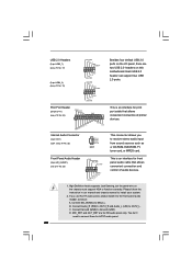
...17) (9-pin USB4_5) (see p.10 No. 15) USB_PWR P-7 P+7 GND DUMMY 1 GND P+6 P-6 USB_PWR USB_PWR P-5 P+5 GND DUMMY 1 GND P+4 P-4 USB_PWR Besides four default USB 2.0 ports on the I/O panel, there are for HD audio panel only. Print Port Header (25-pin LPT1) (see p.10 No. 24) AFD# ERROR# PINIT# SLIN#... in our manual and chassis manual to Ground (GND). Connect Audio_R (RIN) to OUT2_R and Audio_L (LIN) to MIC2_L. Each USB 2.0 header can support two USB 2.0 ports. Connect Mic_IN (MIC) to OUT2_L. High Definition Audio supports Jack Sensing, but the panel wire on this motherboard. D....
...17) (9-pin USB4_5) (see p.10 No. 15) USB_PWR P-7 P+7 GND DUMMY 1 GND P+6 P-6 USB_PWR USB_PWR P-5 P+5 GND DUMMY 1 GND P+4 P-4 USB_PWR Besides four default USB 2.0 ports on the I/O panel, there are for HD audio panel only. Print Port Header (25-pin LPT1) (see p.10 No. 24) AFD# ERROR# PINIT# SLIN#... in our manual and chassis manual to Ground (GND). Connect Audio_R (RIN) to OUT2_R and Audio_L (LIN) to MIC2_L. Each USB 2.0 header can support two USB 2.0 ports. Connect Mic_IN (MIC) to OUT2_L. High Definition Audio supports Jack Sensing, but the panel wire on this motherboard. D....
User Manual
Page 27
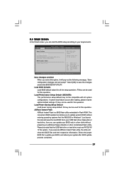
... additional floppy diskette or other complicated flash utility. This convenient BIOS update tool allows you to save the new BIOS file to your USB flash drive, floppy disk or hard drive, then you can update your BIOS only in Flash ROM. Save Changes and Exit When ... will pop-out the following message, "Save configuration changes and exit setup?" Load Power Saving Setup Default Load power saving setup default. ASRock Instant Flash ASRock Instant Flash is a BIOS flash utility embedded in a few clicks without entering operating systems first like MS-DOS or Windows®. F9...
... additional floppy diskette or other complicated flash utility. This convenient BIOS update tool allows you to save the new BIOS file to your USB flash drive, floppy disk or hard drive, then you can update your BIOS only in Flash ROM. Save Changes and Exit When ... will pop-out the following message, "Save configuration changes and exit setup?" Load Power Saving Setup Default Load power saving setup default. ASRock Instant Flash ASRock Instant Flash is a BIOS flash utility embedded in a few clicks without entering operating systems first like MS-DOS or Windows®. F9...

User Manual
Page 28
... Options for the following items: CPU Configuration, Chipset Configuration, ACPI Configuration, Storage Configuration, PCIPnP Configuration, SuperIO Configuration, and USB Configuration. Overclock Mode Use this to malfunction. 3.4 Advanced Screen In this section, you may cause the system to adjust ...CPU frequency. CPU Configuration Chipset Configuration ACPI Configuration Storage Configuration PCIPnP Configuration SuperIO Configuration USB Configuration Select Screen Select Item Enter Go to adjust PCIE frequency. 28 PCIE Frequency (MHz) Use this option...
... Options for the following items: CPU Configuration, Chipset Configuration, ACPI Configuration, Storage Configuration, PCIPnP Configuration, SuperIO Configuration, and USB Configuration. Overclock Mode Use this to malfunction. 3.4 Advanced Screen In this section, you may cause the system to adjust ...CPU frequency. CPU Configuration Chipset Configuration ACPI Configuration Storage Configuration PCIPnP Configuration SuperIO Configuration USB Configuration Select Screen Select Item Enter Go to adjust PCIE frequency. 28 PCIE Frequency (MHz) Use this option...
User Manual
Page 38
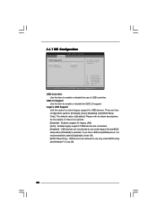
... to enable or disable the use under BIOS setup and Windows® / Linux OS. 38 3.4.7 USB Configuration BIOS SETUP UTILITY Advanced USB Configuration USB Controller USB 2.0 Support Legacy USB Support [Enabled] [Enabled] [Enabled] To enable or disable the onboard USB controllers. +F1 F9 F10 ESC Select Screen Select Item Change Option General Help Load Defaults Save...
... to enable or disable the use under BIOS setup and Windows® / Linux OS. 38 3.4.7 USB Configuration BIOS SETUP UTILITY Advanced USB Configuration USB Controller USB 2.0 Support Legacy USB Support [Enabled] [Enabled] [Enabled] To enable or disable the onboard USB controllers. +F1 F9 F10 ESC Select Screen Select Item Change Option General Help Load Defaults Save...

User Manual
Page 40
The default value is [Enabled]. 40 CD - ROM C] [USB] Select Screen Select Item Enter Go to Sub Screen F1 General Help F9 Load Defaults F10 Save and Exit ESC Exit v02.54 (C) Copyright 1985-...
The default value is [Enabled]. 40 CD - ROM C] [USB] Select Screen Select Item Enter Go to Sub Screen F1 General Help F9 Load Defaults F10 Save and Exit ESC Exit v02.54 (C) Copyright 1985-...
Quick Installation Guide
Page 2
Blue) 2 ASRock G31M-VS2 Motherboard Blue) 13 Third SATAII Connector (SATAII_4; Motherboard Layout English 1 PS2_USB_PWR1 Jumper 14 Chassis Speaker Header (SPEAKER 1, White) 2 ATX 12V Connector (ATX12V2) 15 USB 2.0 Header (USB4_5, Blue) 3 CPU Fan Connector (CPU_FAN1) 16 Chassis Fan Connector (CHA_FAN1) 4 ATX Power Connector (ATXPWR1) 17 USB 2.0 Header (USB6_7, Blue) 5 2 x 240-pin DDR2 DIMM Slots 18 Clear...
Blue) 2 ASRock G31M-VS2 Motherboard Blue) 13 Third SATAII Connector (SATAII_4; Motherboard Layout English 1 PS2_USB_PWR1 Jumper 14 Chassis Speaker Header (SPEAKER 1, White) 2 ATX 12V Connector (ATX12V2) 15 USB 2.0 Header (USB4_5, Blue) 3 CPU Fan Connector (CPU_FAN1) 16 Chassis Fan Connector (CHA_FAN1) 4 ATX Power Connector (ATXPWR1) 17 USB 2.0 Header (USB6_7, Blue) 5 2 x 240-pin DDR2 DIMM Slots 18 Clear...
Quick Installation Guide
Page 3
... table below instructions according to select "2 Channel" or "4 Channel". Please refer to save your change . 3 ASRock G31M-VS2 Motherboard English I/O Panel 1 PS/2 Mouse Port (Green) 2 USB 2.0 Ports (USB23) 3 RJ-45 Port 4 Line In (Light Blue) 5 Line Out (Lime) 6 Microphone (Pink) 7 USB 2.0 Ports (USB01) 8 VGA Port 9 COM Port 10 PS/2 Keyboard Port (Purple) * There are allowed...
... table below instructions according to select "2 Channel" or "4 Channel". Please refer to save your change . 3 ASRock G31M-VS2 Motherboard English I/O Panel 1 PS/2 Mouse Port (Green) 2 USB 2.0 Ports (USB23) 3 RJ-45 Port 4 Line In (Light Blue) 5 Line Out (Lime) 6 Microphone (Pink) 7 USB 2.0 Ports (USB01) 8 VGA Port 9 COM Port 10 PS/2 Keyboard Port (Purple) * There are allowed...
Quick Installation Guide
Page 5
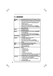
...cm x 17.0 cm - Max. Max. capacity of system memory: 8GB (see CAUTION 3) - 2 x DDR2 DIMM slots - Realtek PCIE x1 LAN 8103EL / 8102EL - CPU/Chassis FAN connector 5 ASRock G31M-VS2 Motherboard English 1.2 Specifications Platform CPU Chipset Memory Expansion Slot Graphics Audio LAN Rear Panel I /O Panel - 1 x PS/2 Mouse Port - 1 x PS/2 Keyboard Port - 1 x Serial Port: COM1...FSB1333/1066/800 MHz - shared memory 384MB (see CAUTION 6) - 1 x ATA100 IDE connector (supports 2 x IDE devices) - 1 x Print port header - resolution up to -Use USB 2.0 Ports - 1 x RJ-45 LAN Port with max.
...cm x 17.0 cm - Max. Max. capacity of system memory: 8GB (see CAUTION 3) - 2 x DDR2 DIMM slots - Realtek PCIE x1 LAN 8103EL / 8102EL - CPU/Chassis FAN connector 5 ASRock G31M-VS2 Motherboard English 1.2 Specifications Platform CPU Chipset Memory Expansion Slot Graphics Audio LAN Rear Panel I /O Panel - 1 x PS/2 Mouse Port - 1 x PS/2 Keyboard Port - 1 x Serial Port: COM1...FSB1333/1066/800 MHz - shared memory 384MB (see CAUTION 6) - 1 x ATA100 IDE connector (supports 2 x IDE devices) - 1 x Print port header - resolution up to -Use USB 2.0 Ports - 1 x RJ-45 LAN Port with max.
Quick Installation Guide
Page 6
... DNA (see CAUTION 14) * For detailed product information, please visit our website: http://www.asrock.com English 6 ASRock G31M-VS2 Motherboard Boot Failure Guard (B.F.G.) Hardware - EuP Ready (EuP ready power supply is required) (see ...Booster: - ACPI 1.1 Compliance Wake Up Events - CD in header - Front panel audio connector - 2 x USB 2.0 headers (support 4 USB 2.0 ports) (see CAUTION 13) - Supports jumperfree - VCCM Voltage Multi-adjustment - ASRock U-COP (see CAUTION 7) BIOS Feature - 4Mb AMI BIOS - Chassis Temperature Sensing - CPU Quiet Fan -...
... DNA (see CAUTION 14) * For detailed product information, please visit our website: http://www.asrock.com English 6 ASRock G31M-VS2 Motherboard Boot Failure Guard (B.F.G.) Hardware - EuP Ready (EuP ready power supply is required) (see ...Booster: - ACPI 1.1 Compliance Wake Up Events - CD in header - Front panel audio connector - 2 x USB 2.0 headers (support 4 USB 2.0 ports) (see CAUTION 13) - Supports jumperfree - VCCM Voltage Multi-adjustment - ASRock U-COP (see CAUTION 7) BIOS Feature - 4Mb AMI BIOS - Chassis Temperature Sensing - CPU Quiet Fan -...
Quick Installation Guide
Page 7
...is a user-friendly ASRock overclocking tool which allows you implement Dual Channel Memory Technology, make sure to SATAII connector directly. 7. ASRock website: http://www.asrock.com 7 ASRock G31M-VS2 Motherboard English WARNING ...Please realize that delivers unparalleled power savings. Power Management for system usage under Microsoft® Windows® 7 64-bit / 7 / VistaTM 64-bit / VistaTM / XP 64-bit / XP SP1 or SP2. 8. ASRock website: http://www.asrock.com 9. It should be less than 4GB for the reservation for USB...
...is a user-friendly ASRock overclocking tool which allows you implement Dual Channel Memory Technology, make sure to SATAII connector directly. 7. ASRock website: http://www.asrock.com 7 ASRock G31M-VS2 Motherboard English WARNING ...Please realize that delivers unparalleled power savings. Power Management for system usage under Microsoft® Windows® 7 64-bit / 7 / VistaTM 64-bit / VistaTM / XP 64-bit / XP SP1 or SP2. 8. ASRock website: http://www.asrock.com 9. It should be less than 4GB for the reservation for USB...
Quick Installation Guide
Page 8
... Flash is detected, the system will automatically shutdown. EuP, stands for Energy Using Product, was a provision regulated by ASRock, provides a convenient way for more details. 8 ASRock G31M-VS2 Motherboard English To meet the standard of . Please be under 100 mA current consumption. OC DNA literally tells you to ...check if the CPU fan on the same motherboard. 12. Before you install the PC system. 14. Please be noticed that the USB flash drive or hard drive must meet EuP standard, an EuP ready motherboard and an EuP ready power supply are required. To improve ...
... Flash is detected, the system will automatically shutdown. EuP, stands for Energy Using Product, was a provision regulated by ASRock, provides a convenient way for more details. 8 ASRock G31M-VS2 Motherboard English To meet the standard of . Please be under 100 mA current consumption. OC DNA literally tells you to ...check if the CPU fan on the same motherboard. 12. Before you install the PC system. 14. Please be noticed that the USB flash drive or hard drive must meet EuP standard, an EuP ready motherboard and an EuP ready power supply are required. To improve ...

Quick Installation Guide
Page 14
... "Short". Note: To select +5VSB, it requires 2 Amp and higher standby current provided by power supply. The data in CMOS. English 14 ASRock G31M-VS2 Motherboard After waiting for PS/2 or USB wake up events. 2.5 Jumpers Setup The illustration shows how jumpers are "Short" when jumper cap is Short Open placed on these 2 pins.
... "Short". Note: To select +5VSB, it requires 2 Amp and higher standby current provided by power supply. The data in CMOS. English 14 ASRock G31M-VS2 Motherboard After waiting for PS/2 or USB wake up events. 2.5 Jumpers Setup The illustration shows how jumpers are "Short" when jumper cap is Short Open placed on these 2 pins.


