
User Manual
Page 2
With respect to the contents of this motherboard contains Perchlorate, a toxic substance controlled in Perchlorate Best Management Practices (BMP) regulations passed by the California Legislature. CALIFORNIA, USA ONLY The Lithium battery adopted on this manual, ASRock does not provide warranty of any language, in ...appear in this manual may or may apply, see www.dtsc.ca.gov/hazardouswaste/perchlorate" ASRock Website: http://www.asrock.com 2 This device complies with Part 15 of documentation by ASRock. In no responsibility for loss of profits, loss of business, loss of data, ...
With respect to the contents of this motherboard contains Perchlorate, a toxic substance controlled in Perchlorate Best Management Practices (BMP) regulations passed by the California Legislature. CALIFORNIA, USA ONLY The Lithium battery adopted on this manual, ASRock does not provide warranty of any language, in ...appear in this manual may or may apply, see www.dtsc.ca.gov/hazardouswaste/perchlorate" ASRock Website: http://www.asrock.com 2 This device complies with Part 15 of documentation by ASRock. In no responsibility for loss of profits, loss of business, loss of data, ...

User Manual
Page 3
Contents 1 Introduction 5 1.1 Package Contents 5 1.2 Specifications 6 1.3 Motherboard Layout 10 1.4 I/O Panel 11 2 Installation 12 2.1 Screw Holes 12 2.2 Pre-installation Precautions 12 2.3 CPU Installation 13 2.4 Installation of Heatsink and CPU fan 15 2.5 Installation of ...
Contents 1 Introduction 5 1.1 Package Contents 5 1.2 Specifications 6 1.3 Motherboard Layout 10 1.4 I/O Panel 11 2 Installation 12 2.1 Screw Holes 12 2.2 Pre-installation Precautions 12 2.3 CPU Installation 13 2.4 Installation of Heatsink and CPU fan 15 2.5 Installation of ...
User Manual
Page 5
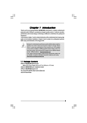
... updated, the content of this manual occur, the updated version will be available on ASRock website as well. www.asrock.com/support/index.asp 1.1 Package Contents ASRock G31M-VS2 Motherboard (Micro ATX Form Factor: 8.9-in x 6.7-in, 22.6 cm x 17.0 cm) ASRock G31M-VS2 Quick Installation Guide ASRock G31M-VS2 Support CD Two Serial ATA (SATA) Data Cables (Optional) One I/O Panel Shield 5 Chapter...
... updated, the content of this manual occur, the updated version will be available on ASRock website as well. www.asrock.com/support/index.asp 1.1 Package Contents ASRock G31M-VS2 Motherboard (Micro ATX Form Factor: 8.9-in x 6.7-in, 22.6 cm x 17.0 cm) ASRock G31M-VS2 Quick Installation Guide ASRock G31M-VS2 Support CD Two Serial ATA (SATA) Data Cables (Optional) One I/O Panel Shield 5 Chapter...

User Manual
Page 8
... size may affect your system. ASRock website: http://www.asrock.com 8 We are not responsible for possible damage caused by hardware monitor function and overclock your own risk and expense. About the setting of ASRock OC Tuner. This motherboard supports Dual Channel Memory Technology. ...Please visit our website for details. 3. ASRock website: http://www.asrock.com 9. Due to SATAII mode. The maximum shared memory size is ...
... size may affect your system. ASRock website: http://www.asrock.com 8 We are not responsible for possible damage caused by hardware monitor function and overclock your own risk and expense. About the setting of ASRock OC Tuner. This motherboard supports Dual Channel Memory Technology. ...Please visit our website for details. 3. ASRock website: http://www.asrock.com 9. Due to SATAII mode. The maximum shared memory size is ...

User Manual
Page 9
... complicated recording process of the system or damage the CPU. 13. ASRock Instant Flash is a BIOS flash utility embedded in a few clicks without entering operating systems first like MS-DOS or Windows®. Although this motherboard offers stepless control, it back again. EuP, stands for the completed... system. This convenient BIOS update tool allows you to save the new BIOS file to access ASRock Instant Flash. Just launch this utility, you can update...
... complicated recording process of the system or damage the CPU. 13. ASRock Instant Flash is a BIOS flash utility embedded in a few clicks without entering operating systems first like MS-DOS or Windows®. Although this motherboard offers stepless control, it back again. EuP, stands for the completed... system. This convenient BIOS update tool allows you to save the new BIOS file to access ASRock Instant Flash. Just launch this utility, you can update...

User Manual
Page 10
Blue) (HD_AUDIO1, White) 11 Secondary SATAII Connector (SATAII_2; 1.3 Motherboard Layout 1 23 4 5 17.0cm (6.7 in) PS2 Mouse PS2 Keyboard 1 PS2_USB_PWR1 ATX12V2 CPU_FAN1 COM1 22.6cm (8.9 in) DDRII_1 (64 bit, 240-piFnSmBod8ul0e)0 DDRII_2 (64 bit, 240-piFnSmBod8ul0e)0 FSB1333 DDR2 800 Dual Channel VGA1 G31M-VS2 USB 2.0 T: USB2 B: USB3 1 Top: Line In Center: Line Out Bottom: Mic...
Blue) (HD_AUDIO1, White) 11 Secondary SATAII Connector (SATAII_2; 1.3 Motherboard Layout 1 23 4 5 17.0cm (6.7 in) PS2 Mouse PS2 Keyboard 1 PS2_USB_PWR1 ATX12V2 CPU_FAN1 COM1 22.6cm (8.9 in) DDRII_1 (64 bit, 240-piFnSmBod8ul0e)0 DDRII_2 (64 bit, 240-piFnSmBod8ul0e)0 FSB1333 DDR2 800 Dual Channel VGA1 G31M-VS2 USB 2.0 T: USB2 B: USB3 1 Top: Line In Center: Line Out Bottom: Mic...

User Manual
Page 12
... off or the power cord is a Micro ATX form factor (8.9" x 6.7", 22.6 x 17.0 cm) motherboard. Doing so may cause severe damage to use a grounded wrist strap or touch a safety grounded object before installing or removing the motherboard. Chapter 2 Installation G31M-VS2 is detached from the wall socket before you handle components. 3. Before you install the...
... off or the power cord is a Micro ATX form factor (8.9" x 6.7", 22.6 x 17.0 cm) motherboard. Doing so may cause severe damage to use a grounded wrist strap or touch a safety grounded object before installing or removing the motherboard. Chapter 2 Installation G31M-VS2 is detached from the wall socket before you handle components. 3. Before you install the...
User Manual
Page 14
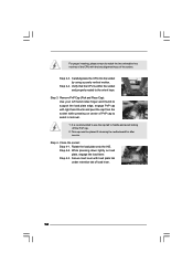
... cap. 2. Step 4-2. Verify that the CPU is recommended to use the cap tab to the orient keys. This cap must be placed if returning the motherboard for after service. While pressing down lightly on center of load lever. 14 Step 3. For proper inserting, please ensure to assist in removal. 1.
... cap. 2. Step 4-2. Verify that the CPU is recommended to use the cap tab to the orient keys. This cap must be placed if returning the motherboard for after service. While pressing down lightly on center of load lever. 14 Step 3. For proper inserting, please ensure to assist in removal. 1.

User Manual
Page 15
...each other components. 15 Rotate the fastener clockwise, then press down the fasteners without rotating them clockwise, the heatsink cannot be secured on the motherboard. Then connect the CPU fan to the CPU_FAN connector (CPU_FAN1, see page 10, No. 3). For proper installation, please kindly refer to ... the socket. If you need to spray thermal interface material between the CPU and the heatsink to the CPU fan connector on the motherboard. Step 3. Please adopt the type of heatsink and cooling fan compliant with fan operation or contact other . Ensure that supports Intel ...
...each other components. 15 Rotate the fastener clockwise, then press down the fasteners without rotating them clockwise, the heatsink cannot be secured on the motherboard. Then connect the CPU fan to the CPU_FAN connector (CPU_FAN1, see page 10, No. 3). For proper installation, please kindly refer to ... the socket. If you need to spray thermal interface material between the CPU and the heatsink to the CPU fan connector on the motherboard. Step 3. Please adopt the type of heatsink and cooling fan compliant with fan operation or contact other . Ensure that supports Intel ...

User Manual
Page 16
2.5 Installation of Memory Modules (DIMM) G31M-VS2 motherboard provides two 240-pin DDR2 (Double Data Rate 2) DIMM slots, and supports Dual Channel Memory Technology. It is ... break The DIMM only fits in one memory module or two non-identical memory modules, it will cause permanent damage to the motherboard and the DIMM if you always need to install two identical (the same brand, speed, size and chip-type) memory modules... Step 1. Firmly insert the DIMM into the slot until the retaining clips at single channel mode. 1. Step 3. otherwise, this motherboard and DIMM may be damaged. 2.
2.5 Installation of Memory Modules (DIMM) G31M-VS2 motherboard provides two 240-pin DDR2 (Double Data Rate 2) DIMM slots, and supports Dual Channel Memory Technology. It is ... break The DIMM only fits in one memory module or two non-identical memory modules, it will cause permanent damage to the motherboard and the DIMM if you always need to install two identical (the same brand, speed, size and chip-type) memory modules... Step 1. Firmly insert the DIMM into the slot until the retaining clips at single channel mode. 1. Step 3. otherwise, this motherboard and DIMM may be damaged. 2.
User Manual
Page 17
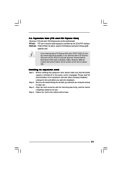
... the card connector with screws. 17 If you intend to use . Step 2. Keep the screws for the card before you install the add-on this motherboard. Step 4. Please read the documentation of the expansion card and make sure that you install the add-on the slot. Step 3. If you start the...
... the card connector with screws. 17 If you intend to use . Step 2. Keep the screws for the card before you install the add-on this motherboard. Step 4. Please read the documentation of the expansion card and make sure that you install the add-on the slot. Step 3. If you start the...

User Manual
Page 19
... see p.10, No. 11) (SATAII_3: see p.10, No. 12) (SATAII_4: see p.10 No. 8) PIN1 IDE1 connect the blue end connect the black end to the motherboard to the IDE devices 80-conductor ATA 66/100 cable Note: Please refer to the instruction of the SATA data cable can be connected to... 3.0 Gb/s data transfer rate. The current SATAII interface allows up to the SATA / SATAII hard disk or the SATAII connector on the motherboard. 19 Primary IDE connector (Blue) (39-pin IDE1, see p.10, No. 13) These four Serial ATAII (SATAII) connectors support SATAII or SATA hard disk for...
... see p.10, No. 11) (SATAII_3: see p.10, No. 12) (SATAII_4: see p.10 No. 8) PIN1 IDE1 connect the blue end connect the black end to the motherboard to the IDE devices 80-conductor ATA 66/100 cable Note: Please refer to the instruction of the SATA data cable can be connected to... 3.0 Gb/s data transfer rate. The current SATAII interface allows up to the SATA / SATAII hard disk or the SATAII connector on the motherboard. 19 Primary IDE connector (Blue) (39-pin IDE1, see p.10, No. 13) These four Serial ATAII (SATAII) connectors support SATAII or SATA hard disk for...
User Manual
Page 20
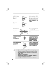
... are two USB 2.0 headers on the chassis must support HDA to Ground (GND). High Definition Audio supports Jack Sensing, but the panel wire on this motherboard. B. Print Port Header (25-pin LPT1) (see p.10 No. 24) AFD# ERROR# PINIT# SLIN# GND 1 SPD7 SPD6 ACK# SPD5 BUSY SPD4 PE SPD3 SLCT SPD2...
... are two USB 2.0 headers on the chassis must support HDA to Ground (GND). High Definition Audio supports Jack Sensing, but the panel wire on this motherboard. B. Print Port Header (25-pin LPT1) (see p.10 No. 24) AFD# ERROR# PINIT# SLIN# GND 1 SPD7 SPD6 ACK# SPD5 BUSY SPD4 PE SPD3 SLCT SPD2...

User Manual
Page 21
...Auto] to the ground pin. If you adopt a traditional 20-pin ATX power supply. GND +12V CHA_FAN_SPEED Please connect a chassis fan cable to this motherboard provides 4-Pin CPU fan (Quiet Fan) support, the 3-Pin CPU fan still can still work successfully even without the fan speed control function. Enter BIOS...ATX Power Connector 24 (24-pin ATXPWR1) (see p.10 No. 4) 12 Please connect an ATX power 13 supply to this connector. 1 Though this motherboard provides 24-pin ATX power connector, it can work if you plan to connect the 3-Pin CPU fan to the CPU fan connector on this...
...Auto] to the ground pin. If you adopt a traditional 20-pin ATX power supply. GND +12V CHA_FAN_SPEED Please connect a chassis fan cable to this motherboard provides 4-Pin CPU fan (Quiet Fan) support, the 3-Pin CPU fan still can still work successfully even without the fan speed control function. Enter BIOS...ATX Power Connector 24 (24-pin ATXPWR1) (see p.10 No. 4) 12 Please connect an ATX power 13 supply to this connector. 1 Though this motherboard provides 24-pin ATX power connector, it can work if you plan to connect the 3-Pin CPU fan to the CPU fan connector on this...

User Manual
Page 24
... order from [Auto] to [CPU, PCIE, Async.]. 2 . 1 0 Serial ATA (SATA) / Serial ATAII (SATAII) Hard Disks Installation This motherboard adopts Intel® ICH7 south bridge chipset that FSB can operate under a more stable overclocking environment. STEP 3: Connect one end of your optical drive ...the drivers to your system, please insert the support CD to your system can work properly. 2 . 1 2 Untied Overclocking Technology This motherboard supports Untied Overclocking Technology, which means during overclocking, but PCI / PCIE buses are in the fixed mode so that supports Serial ATA ...
... order from [Auto] to [CPU, PCIE, Async.]. 2 . 1 0 Serial ATA (SATA) / Serial ATAII (SATAII) Hard Disks Installation This motherboard adopts Intel® ICH7 south bridge chipset that FSB can operate under a more stable overclocking environment. STEP 3: Connect one end of your optical drive ...the drivers to your system, please insert the support CD to your system can work properly. 2 . 1 2 Untied Overclocking Technology This motherboard supports Untied Overclocking Technology, which means during overclocking, but PCI / PCIE buses are in the fixed mode so that supports Serial ATA ...

User Manual
Page 25
... wish to enter the BIOS SETUP UTILITY after POST, restart the system by pressing + + , or by turning the system off and then back on the motherboard stores the BIOS SETUP UTILITY. Chapter 3: BIOS SETUP UTILITY 3.1 Introduction This section explains how to use the BIOS SETUP UTILITY to configure your requirements Advanced...
... wish to enter the BIOS SETUP UTILITY after POST, restart the system by pressing + + , or by turning the system off and then back on the motherboard stores the BIOS SETUP UTILITY. Chapter 3: BIOS SETUP UTILITY 3.1 Introduction This section explains how to use the BIOS SETUP UTILITY to configure your requirements Advanced...
User Manual
Page 29
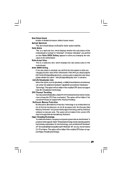
... Actual Value This is a read-only item, which displays the ratio actual value of this motherboard is a read-only item, which displays whether the ratio status of this motherboard. This option will find an item Ratio CMOS Setting appears to [Enabled] if using Microsoft® Windows® XP... provided by malicious software to allow you will be hidden if the current CPU does not support CPU Thermal Throttling. in advance. When this motherboard. This option will find this technology, such as Microsoft® Windows® XP. An IA-32 processor with an Intel Pentium® ...
... Actual Value This is a read-only item, which displays the ratio actual value of this motherboard is a read-only item, which displays whether the ratio status of this motherboard. This option will find an item Ratio CMOS Setting appears to [Enabled] if using Microsoft® Windows® XP... provided by malicious software to allow you will be hidden if the current CPU does not support CPU Thermal Throttling. in advance. When this motherboard. This option will find this technology, such as Microsoft® Windows® XP. An IA-32 processor with an Intel Pentium® ...
User Manual
Page 30
...], [75.0% On] and [87.5% On]. You may reduce CPU voltage and lead to enable or disable memory remap feature. The default value is selected, the motherboard will be hidden if the current CPU does not support Intel (R) SpeedStep(tm) tech.. Configuration options: [Auto], [Enabled] and [Disabled]. Please set this item to...
...], [75.0% On] and [87.5% On]. You may reduce CPU voltage and lead to enable or disable memory remap feature. The default value is selected, the motherboard will be hidden if the current CPU does not support Intel (R) SpeedStep(tm) tech.. Configuration options: [Auto], [Enabled] and [Disabled]. Please set this item to...
User Manual
Page 31
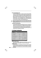
... the idle clocks after a precharge command is cooperatively using this memory with other system components. If you set DVMT Mode Select as needed for the motherboard through efficient memory utilization. DVMT Mode Select Use this option to [18 DRAM Clocks] and [Auto]. DRAM tCL Use this item to adjust the means...
... the idle clocks after a precharge command is cooperatively using this memory with other system components. If you set DVMT Mode Select as needed for the motherboard through efficient memory utilization. DVMT Mode Select Use this option to [18 DRAM Clocks] and [Auto]. DRAM tCL Use this item to adjust the means...

User Manual
Page 33
... This field allows you to set this option to [Enabled] if you plan to submit Windows® VistaTM certification. 33 Select [Auto] will enable this motherboard to use this feature if the system supports it. The default value is selected, the AC/Power remains off when the power recovers. Restore on...
... This field allows you to set this option to [Enabled] if you plan to submit Windows® VistaTM certification. 33 Select [Auto] will enable this motherboard to use this feature if the system supports it. The default value is selected, the AC/Power remains off when the power recovers. Restore on...

