
User Manual
Page 3
... 5 1.2 Specifications 6 1.3 Motherboard Layout 10 1.4 I/O Panel (G31M-GS 11 1.5 I/O Panel (G31M-S 12 2 Installation 13 2.1 Screw Holes 13 2.2 Pre-installation Precautions 13 2.3 CPU Installation 14 2.4 Installation of Heatsink and CPU fan 16 2.5 Installation of Memory Modules (DIMM 17 2.6 Expansion ... BIOS Menu Bar 27 3.1.2 Navigation Keys 28 3.2 Main Screen 28 3.3 Smart Screen 30 3.4 Advanced Screen 31 3.4.1 CPU Configuration 31 3.4.2 Chipset Configuration 33 3.4.3 ACPI Configuration 36 3.4.4 IDE Configuration 37 3.4.5 PCIPnP Configuration 39 3.4.6 Floppy Configuration 40...
... 5 1.2 Specifications 6 1.3 Motherboard Layout 10 1.4 I/O Panel (G31M-GS 11 1.5 I/O Panel (G31M-S 12 2 Installation 13 2.1 Screw Holes 13 2.2 Pre-installation Precautions 13 2.3 CPU Installation 14 2.4 Installation of Heatsink and CPU fan 16 2.5 Installation of Memory Modules (DIMM 17 2.6 Expansion ... BIOS Menu Bar 27 3.1.2 Navigation Keys 28 3.2 Main Screen 28 3.3 Smart Screen 30 3.4 Advanced Screen 31 3.4.1 CPU Configuration 31 3.4.2 Chipset Configuration 33 3.4.3 ACPI Configuration 36 3.4.4 IDE Configuration 37 3.4.5 PCIPnP Configuration 39 3.4.6 Floppy Configuration 40...
User Manual
Page 5
...this manual will be subject to quality and endurance. www.asrock.com/support/index.asp 1.1 Package Contents ASRock G31M-GS / G31M-S Motherboard (Micro ATX Form Factor: 9.6-in x 7.2-in, 24.4 cm x 18.3 cm) ASRock G31M-GS / G31M-S Quick Installation Guide ASRock G31M-GS / G31M-S Support CD One 80-conductor Ultra ATA 66/100 IDE ... be updated, the content of the Support CD. It delivers excellent performance with robust design conforming to ASRock's commitment to change without further notice. You may find the latest VGA cards and CPU support lists on ASRock website without notice.
...this manual will be subject to quality and endurance. www.asrock.com/support/index.asp 1.1 Package Contents ASRock G31M-GS / G31M-S Motherboard (Micro ATX Form Factor: 9.6-in x 7.2-in, 24.4 cm x 18.3 cm) ASRock G31M-GS / G31M-S Quick Installation Guide ASRock G31M-GS / G31M-S Support CD One 80-conductor Ultra ATA 66/100 IDE ... be updated, the content of the Support CD. It delivers excellent performance with robust design conforming to ASRock's commitment to change without further notice. You may find the latest VGA cards and CPU support lists on ASRock website without notice.
User Manual
Page 6
...800/667 non-ECC, un-buffered memory (see CAUTION 3) - Pixel Shader 2.0, DirectX 9.0 - G31M-S Realtek PCIE x1 LAN 8103EL / 8102EL, speed 10/100 Mb/s - Supports Untied Overclocking Technology (see CAUTION 5) - 1.2 Specifications Platform CPU Chipset Memory Expansion Slot Graphics Audio LAN Rear Panel I /O Panel - 1 x PS/2 Mouse Port...LAN Port with all FSB1600/1333/1066/800MHz CPUs (see CAUTION 1) - shared memory 384MB (see CAUTION 4) - 2 x DDR2 DIMM slots - G31M-GS Realtek PCIE x 1 Gigabit LAN RTL8111DL, speed 10/100/1000 Mb/s - Compatible with LED (ACT/LINK LED and SPEED LED) LGA 775 ...
...800/667 non-ECC, un-buffered memory (see CAUTION 3) - Pixel Shader 2.0, DirectX 9.0 - G31M-S Realtek PCIE x1 LAN 8103EL / 8102EL, speed 10/100 Mb/s - Supports Untied Overclocking Technology (see CAUTION 5) - 1.2 Specifications Platform CPU Chipset Memory Expansion Slot Graphics Audio LAN Rear Panel I /O Panel - 1 x PS/2 Mouse Port...LAN Port with all FSB1600/1333/1066/800MHz CPUs (see CAUTION 1) - shared memory 384MB (see CAUTION 4) - 2 x DDR2 DIMM slots - G31M-GS Realtek PCIE x 1 Gigabit LAN RTL8111DL, speed 10/100/1000 Mb/s - Compatible with LED (ACT/LINK LED and SPEED LED) LGA 775 ...
User Manual
Page 7
... CAUTION 9) BIOS Feature - 4Mb AMI BIOS - Boot Failure Guard (B.F.G.) Hardware - ASRock OC Tuner (see CAUTION 14) - ASRock U-COP (see CAUTION 10) - Chassis Fan Tachometer - CPU/Chassis FAN connector - 24 pin ATX power connector - 4 pin 12V power connector... Stepless Control (see CAUTION 15) * For detailed product information, please visit our website: http://www.asrock.com 7 CPU Temperature Sensing Monitor - Supports "Plug and Play" - AMI Legal BIOS - ASRock Instant Flash (see CAUTION 8) - 1 x ATA100 IDE connector (supports 2 x IDE devices) - 1 x ...
... CAUTION 9) BIOS Feature - 4Mb AMI BIOS - Boot Failure Guard (B.F.G.) Hardware - ASRock OC Tuner (see CAUTION 14) - ASRock U-COP (see CAUTION 10) - Chassis Fan Tachometer - CPU/Chassis FAN connector - 24 pin ATX power connector - 4 pin 12V power connector... Stepless Control (see CAUTION 15) * For detailed product information, please visit our website: http://www.asrock.com 7 CPU Temperature Sensing Monitor - Supports "Plug and Play" - AMI Legal BIOS - ASRock Instant Flash (see CAUTION 8) - 1 x ATA100 IDE connector (supports 2 x IDE devices) - 1 x ...
User Manual
Page 8
...also need to 120MHz. This motherboard supports Untied Overclocking Technology. Please read "Untied Overclocking Technology" on page 26 for proper jumper settings. 2. CPU FSB Frequency Memory Support Frequency 1600 DDR2 800 1333 DDR2 667, DDR2 800 1066 DDR2 667, DDR2 800 800 DDR2 667, DDR2 800 6.... / XP 64-bit / XP SP1 or SP2 / 2000 SP4. 8 WARNING Please realize that there is a certain risk involved with 64-bit CPU, there is no such limitation. 7. Before you implement Dual Channel Memory Technology, make sure to the operating system limitation, the actual memory size may...
...also need to 120MHz. This motherboard supports Untied Overclocking Technology. Please read "Untied Overclocking Technology" on page 26 for proper jumper settings. 2. CPU FSB Frequency Memory Support Frequency 1600 DDR2 800 1333 DDR2 667, DDR2 800 1066 DDR2 667, DDR2 800 800 DDR2 667, DDR2 800 6.... / XP 64-bit / XP SP1 or SP2 / 2000 SP4. 8 WARNING Please realize that there is a certain risk involved with 64-bit CPU, there is no such limitation. 7. Before you implement Dual Channel Memory Technology, make sure to the operating system limitation, the actual memory size may...
User Manual
Page 9
... the heatsink when you to update system BIOS without entering operating systems first like MS-DOS or Windows®. ASRock website: http://www.asrock.com 11. While CPU overheat is a revolutionary technology that the USB flash drive or hard drive must meet EuP standard, an EuP ready motherboard..., the EuP ready power supply must use FAT32/16/12 file system. 13. ASRock Instant Flash is higher than the recommended CPU bus frequencies may cause the instability of the system or damage the CPU. 14. Please be under Windows® environment. To meet the standard of the...
... the heatsink when you to update system BIOS without entering operating systems first like MS-DOS or Windows®. ASRock website: http://www.asrock.com 11. While CPU overheat is a revolutionary technology that the USB flash drive or hard drive must meet EuP standard, an EuP ready motherboard..., the EuP ready power supply must use FAT32/16/12 file system. 13. ASRock Instant Flash is higher than the recommended CPU bus frequencies may cause the instability of the system or damage the CPU. 14. Please be under Windows® environment. To meet the standard of the...
User Manual
Page 10
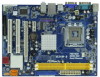
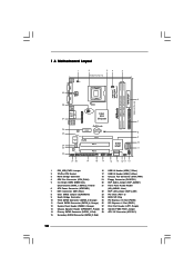
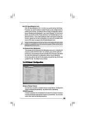
..., 240-piFnSmBod8ul0e)0 24.4cm (9.6 in) SATAII_3 SATAII_4 6 7 8 9 10 11 1 PS2_USB_PWR1 Jumper 16 USB 2.0 Header (USB6_7, Blue) 2 775-Pin CPU Socket 17 USB 2.0 Header (USB4_5, Blue) 3 North Bridge Controller 18 Chassis Fan Connector (CHA_FAN1) 4 CPU Fan Connector (CPU_FAN1) 19 Floppy Connector (FLOPPY1) 5 2 x 240-pin DDR2 DIMM Slots 20 EUP Audio Jumper (EUP_AUDIO1) (Dual...
..., 240-piFnSmBod8ul0e)0 24.4cm (9.6 in) SATAII_3 SATAII_4 6 7 8 9 10 11 1 PS2_USB_PWR1 Jumper 16 USB 2.0 Header (USB6_7, Blue) 2 775-Pin CPU Socket 17 USB 2.0 Header (USB4_5, Blue) 3 North Bridge Controller 18 Chassis Fan Connector (CHA_FAN1) 4 CPU Fan Connector (CPU_FAN1) 19 Floppy Connector (FLOPPY1) 5 2 x 240-pin DDR2 DIMM Slots 20 EUP Audio Jumper (EUP_AUDIO1) (Dual...

User Manual
Page 14
... Rotate the load lever to fully open position at approximately 135 degrees. Orient the CPU with black lines. Step 1. Do not force to fully open position at approximately 100 degrees. Step 2. Hold the CPU by depressing down and out on the socket. Step 2-2. Pin1 orientation key notch ... Step 1-3. Rotate the load plate to insert the CPU into the socket, please check if the CPU surface is unclean or if there is found. Insert the 775-LAND CPU: Step 2-1. 2.3 CPU Installation For the installation of Intel 775-LAND CPU, please follow the steps below. 775-Pin Socket ...
... Rotate the load lever to fully open position at approximately 135 degrees. Orient the CPU with black lines. Step 1. Do not force to fully open position at approximately 100 degrees. Step 2. Hold the CPU by depressing down and out on the socket. Step 2-2. Pin1 orientation key notch ... Step 1-3. Rotate the load plate to insert the CPU into the socket, please check if the CPU surface is unclean or if there is found. Insert the 775-LAND CPU: Step 2-1. 2.3 CPU Installation For the installation of Intel 775-LAND CPU, please follow the steps below. 775-Pin Socket ...
User Manual
Page 15
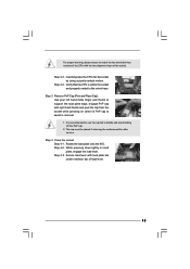
... the socket and properly mated to handle and avoid kicking off the PnP cap. 2. Rotate the load plate onto the IHS. Step 4-3. Verify that the CPU is recommended to use the cap tab to the orient keys. Secure load lever with the two alignment keys of load lever. 15 For proper... service. Close the socket: Step 4-1. Step 2-4. Step 4. While pressing down lightly on center of PnP cap to match the two orientation key notches of the CPU with load plate tab under retention tab of the socket. Step 3. Remove PnP Cap (Pick and Place Cap): Use your left hand index finger and...
... the socket and properly mated to handle and avoid kicking off the PnP cap. 2. Rotate the load plate onto the IHS. Step 4-3. Verify that the CPU is recommended to use the cap tab to the orient keys. Secure load lever with the two alignment keys of load lever. 15 For proper... service. Close the socket: Step 4-1. Step 2-4. Step 4. While pressing down lightly on center of PnP cap to match the two orientation key notches of the CPU with load plate tab under retention tab of the socket. Step 3. Remove PnP Cap (Pick and Place Cap): Use your left hand index finger and...
User Manual
Page 16
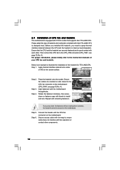
...the instruction manuals of heatsink and cooling fan compliant with the motherboard throughholes. Align fasteners with Intel 775-LAND CPU to dissipate heat. Below is equipped with the CPU fan connector on the motherboard (CPU_FAN1, see page 10, No. 4). Step 4. Step 2. Ensure fan cables...Secure excess cable with tie-wrap to ensure cable does not interfere with remaining fasteners. Ensure that supports Intel 775-LAND CPU. Then connect the CPU fan to improve heat dissipation. Step 1. Place the heatsink onto the socket. If you need to spray thermal interface ...
...the instruction manuals of heatsink and cooling fan compliant with the motherboard throughholes. Align fasteners with Intel 775-LAND CPU to dissipate heat. Below is equipped with the CPU fan connector on the motherboard (CPU_FAN1, see page 10, No. 4). Step 4. Step 2. Ensure fan cables...Secure excess cable with tie-wrap to ensure cable does not interfere with remaining fasteners. Ensure that supports Intel 775-LAND CPU. Then connect the CPU fan to improve heat dissipation. Step 1. Place the heatsink onto the socket. If you need to spray thermal interface ...
User Manual
Page 20
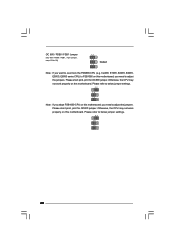
..., see p.10 No. 28) 1_2 1_2 Default 1_2 Note: If you want to below jumper settings. 2_3 1_2 1_2 Note: If you adopt FSB1600-CPU on this motherboard, you need to adjust the jumpers. Please short pin2, pin3 for OC800 jumper. Otherwise, the... CPU may not work properly on this motherboard. Please refer to overclock the FSB800-CPU (e.g. Cel400, E1000, E2000, E4000, E5000, E6000 series CPU) to FSB1066 on this motherboard, you need to adjust the jumpers. Otherwise, the...
..., see p.10 No. 28) 1_2 1_2 Default 1_2 Note: If you want to below jumper settings. 2_3 1_2 1_2 Note: If you adopt FSB1600-CPU on this motherboard, you need to adjust the jumpers. Please short pin2, pin3 for OC800 jumper. Otherwise, the... CPU may not work properly on this motherboard. Please refer to overclock the FSB800-CPU (e.g. Cel400, E1000, E2000, E4000, E5000, E6000 series CPU) to FSB1066 on this motherboard, you need to adjust the jumpers. Otherwise, the...
User Manual
Page 23
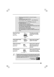
...2000 / XP / XP 64-bit OS: Please select "Front Mic" as the default record device. If you plan to connect the 3-Pin CPU fan to the CPU fan connector on this header. Pin 1-3 Connected 3-Pin Fan Installation 23 Click "Set Default Device" to hear your voice through front mic, please... (4-pin SPEAKER 1) (see p.10 No. 18) GND +12V CHA_FAN_SPEED Please connect a chassis fan cable to this motherboard provides 4-Pin CPU fan (Quiet Fan) support, the 3-Pin CPU fan still can work successfully even without the fan speed control function. Though this connector and match the black wire to the...
...2000 / XP / XP 64-bit OS: Please select "Front Mic" as the default record device. If you plan to connect the 3-Pin CPU fan to the CPU fan connector on this header. Pin 1-3 Connected 3-Pin Fan Installation 23 Click "Set Default Device" to hear your voice through front mic, please... (4-pin SPEAKER 1) (see p.10 No. 18) GND +12V CHA_FAN_SPEED Please connect a chassis fan cable to this motherboard provides 4-Pin CPU fan (Quiet Fan) support, the 3-Pin CPU fan still can work successfully even without the fan speed control function. Though this connector and match the black wire to the...
User Manual
Page 26
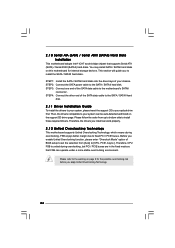
... internal storage devices. Before you install can be auto-detected and listed on this motherboard for the possible overclocking risk before you to [CPU, PCIE, Async.]. Then, the drivers compatible to your system can work properly. 2 . 1 2 Untied Overclocking Technology This motherboard supports...Driver Installation Guide To install the drivers to your system, please insert the support CD to fixed PCI / PCIE buses. Therefore, CPU FSB is untied during overclocking, FSB enjoys better margin due to your chassis. This section will guide you apply Untied Overclocking Technology....
... internal storage devices. Before you install can be auto-detected and listed on this motherboard for the possible overclocking risk before you to [CPU, PCIE, Async.]. Then, the drivers compatible to your system can work properly. 2 . 1 2 Untied Overclocking Technology This motherboard supports...Driver Installation Guide To install the drivers to your system, please insert the support CD to fixed PCI / PCIE buses. Therefore, CPU FSB is untied during overclocking, FSB enjoys better margin due to your chassis. This section will guide you apply Untied Overclocking Technology....
User Manual
Page 28
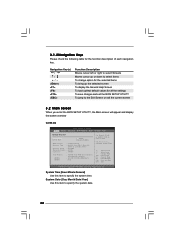
...exit the current screen 3.2 Main Screen When you enter the BIOS SETUP UTILITY, the Main screen will appear and display the system overview G31M-GS BIOS SETUP UTILITY Main Smart Advanced H/W Monitor Boot Security Exit System Overview System Time System Date [14:00:09] [Mon 06/...15/2009] BIOS Version : G31M-GS P1.00 Processor Type : Intel(R) Core(TM) 2 Duo CPU E6540 @ 2.33GHz (64bit) Processor Speed : 2333MHz Microcode Update : 6FB/B6 Cache Size : 4096KB Total Memory DDRII 1 DDRII 2...
...exit the current screen 3.2 Main Screen When you enter the BIOS SETUP UTILITY, the Main screen will appear and display the system overview G31M-GS BIOS SETUP UTILITY Main Smart Advanced H/W Monitor Boot Security Exit System Overview System Time System Date [14:00:09] [Mon 06/...15/2009] BIOS Version : G31M-GS P1.00 Processor Type : Intel(R) Core(TM) 2 Duo CPU E6540 @ 2.33GHz (64bit) Processor Speed : 2333MHz Microcode Update : 6FB/B6 Cache Size : 4096KB Total Memory DDRII 1 DDRII 2...
User Manual
Page 29
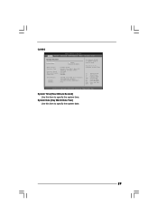
...system date. 29 System Time [Hour:Minute:Second] Use this item to specify the system time. Use [+] or [-] to select a field. G31M-S BIOS SETUP UTILITY Main Smart Advanced H/W Monitor Boot Security Exit System Overview System Time System Date [14:00:09] [Mon 06/15/2009...] BIOS Version : G31M-S P1.00 Processor Type : Intel(R) Core(TM) 2 Duo CPU E6540 @ 2.33GHz (64bit) Processor Speed : 2333MHz Microcode Update : 6FB/B6 Cache Size : 4096KB Total Memory DDRII 1 DDRII 2...
...system date. 29 System Time [Hour:Minute:Second] Use this item to specify the system time. Use [+] or [-] to select a field. G31M-S BIOS SETUP UTILITY Main Smart Advanced H/W Monitor Boot Security Exit System Overview System Time System Date [14:00:09] [Mon 06/15/2009...] BIOS Version : G31M-S P1.00 Processor Type : Intel(R) Core(TM) 2 Duo CPU E6540 @ 2.33GHz (64bit) Processor Speed : 2333MHz Microcode Update : 6FB/B6 Cache Size : 4096KB Total Memory DDRII 1 DDRII 2...

User Manual
Page 31
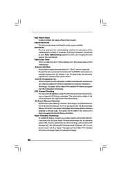
...Select Screen Select Item Enter Go to adjust PCIE frequency. 31 Overclock Mode Use this section, you may set the configurations for CPU WARNING : Setting wrong values in this option to malfunction. The default value is [Auto]. 3.4 Advanced Screen In this to...(C) Copyright 1985-2005, American Megatrends, Inc. Setting wrong values in below sections may cause the system to malfunction. 3.4.1 CPU Configuration BIOS SETUP UTILITY Advanced CPU Configuration Overclock Mode CPU Frequency (MHz) PCIE Frequency (MHz) Boot Failure Guard Spread Spectrum [Auto] [200] [100] [Enabled] [Auto...
...Select Screen Select Item Enter Go to adjust PCIE frequency. 31 Overclock Mode Use this section, you may set the configurations for CPU WARNING : Setting wrong values in this option to malfunction. The default value is [Auto]. 3.4 Advanced Screen In this to...(C) Copyright 1985-2005, American Megatrends, Inc. Setting wrong values in below sections may cause the system to malfunction. 3.4.1 CPU Configuration BIOS SETUP UTILITY Advanced CPU Configuration Overclock Mode CPU Frequency (MHz) PCIE Frequency (MHz) Boot Failure Guard Spread Spectrum [Auto] [200] [100] [Enabled] [Auto...
User Manual
Page 32
...Protection No-Execution (NX) Memory Protection Technology is set to execute code. Spread Spectrum This item should always be hidden if the current CPU does not support No-Excute Memory Protection. If it requires a computer system with "No Execute (NX) Memory Protection" can utilize ... caches. Ratio Status This is "Locked" or "Unlocked". Intel (R) Virtualization tech. This option will be hidden if the current CPU does not support CPU Thermal Throttling. Hyper Threading Technology To enable this feature, it shows "Unlocked", you will find an item Ratio CMOS Setting appears...
...Protection No-Execution (NX) Memory Protection Technology is set to execute code. Spread Spectrum This item should always be hidden if the current CPU does not support No-Excute Memory Protection. If it requires a computer system with "No Execute (NX) Memory Protection" can utilize ... caches. Ratio Status This is "Locked" or "Unlocked". Intel (R) Virtualization tech. This option will be hidden if the current CPU does not support CPU Thermal Throttling. Hyper Threading Technology To enable this feature, it shows "Unlocked", you will find an item Ratio CMOS Setting appears...
User Manual
Page 33
...enable this function, please set this function. On-Demand Clock Modulation This provides the On-Demand Clock Modulation duty cycle. You may reduce CPU voltage and lead to [Disable] if above the total physical memory. Please note that enabling this function may also select other 25% slacking...item to enable power savings. DRAM Frequency If [Auto] is [Disabled]. The default value is selected, the motherboard will be hidden if the current CPU does not support Intel (R) SpeedStep(tm) tech.. Intel (R) SpeedStep(tm) tech. DISABLE: Do not allow remapping of the time, and spend ...
...enable this function, please set this function. On-Demand Clock Modulation This provides the On-Demand Clock Modulation duty cycle. You may reduce CPU voltage and lead to [Disable] if above the total physical memory. Please note that enabling this function may also select other 25% slacking...item to enable power savings. DRAM Frequency If [Auto] is [Disabled]. The default value is selected, the motherboard will be hidden if the current CPU does not support Intel (R) SpeedStep(tm) tech.. Intel (R) SpeedStep(tm) tech. DISABLE: Do not allow remapping of the time, and spend ...

User Manual
Page 42
... 65 C/149 F. You can freely adjust the target fan speed according to enter OS. [BIOS Setup Only] - If you adjusting them. Target CPU Temperature The target temperature will operate in full speed. If you have USB compatibility issue, it allows you choose. USB devices are allowed to use... setup and Windows / Linux OS. 3.5 Hardware Health Event Monitoring Screen In this section, it is recommended to select [Disabled] to the target CPU temperature that you to use under legacy OS and BIOS setup when [Disabled] is [50 C/122 F]. USB devices are not allowed to monitor ...
... 65 C/149 F. You can freely adjust the target fan speed according to enter OS. [BIOS Setup Only] - If you adjusting them. Target CPU Temperature The target temperature will operate in full speed. If you have USB compatibility issue, it allows you choose. USB devices are allowed to use... setup and Windows / Linux OS. 3.5 Hardware Health Event Monitoring Screen In this section, it is recommended to select [Disabled] to the target CPU temperature that you to use under legacy OS and BIOS setup when [Disabled] is [50 C/122 F]. USB devices are not allowed to monitor ...
Quick Installation Guide
Page 2
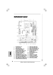
... PCI Express x16 Slot (PCIE2) 11 Fourth SATAII Connector (SATAII_4; Red) 29 ATX 12V Connector (ATX12V1) 15 Secondary SATAII Connector (SATAII_2; Red) 2 ASRock G31M-GS / G31M-S Motherboard Motherboard Layout English 1 PS2_USB_PWR1 Jumper 16 USB 2.0 Header (USB6_7, Blue) 2 775-Pin CPU Socket 17 USB 2.0 Header (USB4_5, Blue) 3 North Bridge Controller 18 Chassis Fan Connector (CHA_FAN1...
... PCI Express x16 Slot (PCIE2) 11 Fourth SATAII Connector (SATAII_4; Red) 29 ATX 12V Connector (ATX12V1) 15 Secondary SATAII Connector (SATAII_2; Red) 2 ASRock G31M-GS / G31M-S Motherboard Motherboard Layout English 1 PS2_USB_PWR1 Jumper 16 USB 2.0 Header (USB6_7, Blue) 2 775-Pin CPU Socket 17 USB 2.0 Header (USB4_5, Blue) 3 North Bridge Controller 18 Chassis Fan Connector (CHA_FAN1...


