User Manual
Page 2
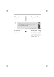
... harmful interference, and (2) this device must accept any interference received, including interference that may cause undesired operation. ASRock assumes no event shall ASRock, its directors, officers, employees, or agents be reproduced, transcribed, transmitted, or translated in any language, in...a particular purpose. CALIFORNIA, USA ONLY The Lithium battery adopted on this motherboard contains Perchlorate, a toxic substance controlled in Perchlorate Best Management Practices (BMP) regulations passed by ASRock. When you discard the Lithium battery in California, USA, please follow ...
... harmful interference, and (2) this device must accept any interference received, including interference that may cause undesired operation. ASRock assumes no event shall ASRock, its directors, officers, employees, or agents be reproduced, transcribed, transmitted, or translated in any language, in...a particular purpose. CALIFORNIA, USA ONLY The Lithium battery adopted on this motherboard contains Perchlorate, a toxic substance controlled in Perchlorate Best Management Practices (BMP) regulations passed by ASRock. When you discard the Lithium battery in California, USA, please follow ...

User Manual
Page 3
Contents 1 Introduction 5 1.1 Package Contents 5 1.2 Specifications 6 1.3 Motherboard Layout 10 1.4 I/O Panel (G31M-GS 11 1.5 I/O Panel (G31M-S 12 2 Installation 13 2.1 Screw Holes 13 2.2 Pre-installation Precautions 13 2.3 CPU Installation 14 2.4 Installation of Heatsink and CPU fan 16 2.5 Installation of Memory Modules (DIMM ...
Contents 1 Introduction 5 1.1 Package Contents 5 1.2 Specifications 6 1.3 Motherboard Layout 10 1.4 I/O Panel (G31M-GS 11 1.5 I/O Panel (G31M-S 12 2 Installation 13 2.1 Screw Holes 13 2.2 Pre-installation Precautions 13 2.3 CPU Installation 14 2.4 Installation of Heatsink and CPU fan 16 2.5 Installation of Memory Modules (DIMM ...
User Manual
Page 5
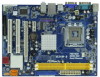
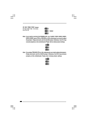
.../support/index.asp 1.1 Package Contents ASRock G31M-GS / G31M-S Motherboard (Micro ATX Form Factor: 9.6-in x 7.2-in, 24.4 cm x 18.3 cm) ASRock G31M-GS / G31M-S Quick Installation Guide ASRock G31M-GS / G31M-S Support CD One 80-conductor Ultra ATA 66/100 IDE Ribbon Cable (Optional... technical support related to this motherboard, please visit our website for purchasing ASRock G31M-GS / G31M-S motherboard, a reliable motherboard produced under ASRock's consistently stringent quality control. It delivers excellent performance with robust design conforming to ASRock's commitment to BIOS setup and...
.../support/index.asp 1.1 Package Contents ASRock G31M-GS / G31M-S Motherboard (Micro ATX Form Factor: 9.6-in x 7.2-in, 24.4 cm x 18.3 cm) ASRock G31M-GS / G31M-S Quick Installation Guide ASRock G31M-GS / G31M-S Support CD One 80-conductor Ultra ATA 66/100 IDE Ribbon Cable (Optional... technical support related to this motherboard, please visit our website for purchasing ASRock G31M-GS / G31M-S motherboard, a reliable motherboard produced under ASRock's consistently stringent quality control. It delivers excellent performance with robust design conforming to ASRock's commitment to BIOS setup and...
User Manual
Page 8
.... 3. Besides, if you want to overclock the CPU you adopt from FSB800 to FSB1066, you need to adjust the jumpers. This motherboard supports Untied Overclocking Technology. Before you also need to adjust the jumpers. The maximum shared memory size is defined by overclocking. FSB1600-CPU...USB 2.0 works fine under Windows® XP and Windows® VistaTM. Please refer to adjust your own risk and expense. This motherboard supports Dual Channel Memory Technology. Due to the operating system limitation, the actual memory size may affect your system stability, or even ...
.... 3. Besides, if you want to overclock the CPU you adopt from FSB800 to FSB1066, you need to adjust the jumpers. This motherboard supports Untied Overclocking Technology. Before you also need to adjust the jumpers. The maximum shared memory size is defined by overclocking. FSB1600-CPU...USB 2.0 works fine under Windows® XP and Windows® VistaTM. Please refer to adjust your own risk and expense. This motherboard supports Dual Channel Memory Technology. Due to the operating system limitation, the actual memory size may affect your system stability, or even ...
User Manual
Page 9
... to access ASRock Instant Flash. According to update system BIOS without sacrificing computing performance. In other than 50% under 1.00W in Flash ROM. For EuP ready power supply selection, we recommend you resume the system, please check if the CPU fan on the motherboard functions properly ...and unplug the power cord, then plug it is higher than the recommended CPU bus frequencies may cause the instability of Intelligent Energy Saver. 10. ASRock website: http://www.asrock.com 12. This convenient BIOS update tool ...
... to access ASRock Instant Flash. According to update system BIOS without sacrificing computing performance. In other than 50% under 1.00W in Flash ROM. For EuP ready power supply selection, we recommend you resume the system, please check if the CPU fan on the motherboard functions properly ...and unplug the power cord, then plug it is higher than the recommended CPU bus frequencies may cause the instability of Intelligent Energy Saver. 10. ASRock website: http://www.asrock.com 12. This convenient BIOS update tool ...
User Manual
Page 10
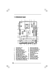
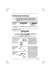
Orange) 25 PCI Express x16 Slot (PCIE2) 11 Fourth SATAII Connector (SATAII_4; Red) 29 ATX 12V Connector (ATX12V1) 15 Secondary SATAII Connector (SATAII_2; 1.3 Motherboard Layout 29 COM1 PS2 Mouse PS2 Keyboard 1 2 34 5 18.3cm (7.2 in) 1 PS2_USB_PWR1 CPU_FAN1 ATX12V1 VGA1 LPT1 1 Top: Line In Center: Line Out Bottom: Mic In ...
Orange) 25 PCI Express x16 Slot (PCIE2) 11 Fourth SATAII Connector (SATAII_4; Red) 29 ATX 12V Connector (ATX12V1) 15 Secondary SATAII Connector (SATAII_2; 1.3 Motherboard Layout 29 COM1 PS2 Mouse PS2 Keyboard 1 2 34 5 18.3cm (7.2 in) 1 PS2_USB_PWR1 CPU_FAN1 ATX12V1 VGA1 LPT1 1 Top: Line In Center: Line Out Bottom: Mic In ...
User Manual
Page 13
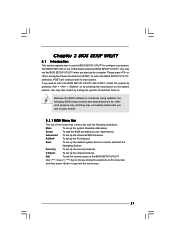
...damages to you install or remove any component, place it . Failure to do so may damage the motherboard. 2.2 Pre-installation Precautions Take note of your motherboard directly on a grounded antistatic pad or in the bag that the power is switched off or the ...motherboard components. 2.1 Screw Holes Place screws into it on the carpet or the like. Chapter 2 Installation G31M-GS / G31M-S is detached from the wall socket before installing or removing the motherboard. Failure to unplug the power cord before touching any motherboard settings. 1. Whenever you install motherboard...
...damages to you install or remove any component, place it . Failure to do so may damage the motherboard. 2.2 Pre-installation Precautions Take note of your motherboard directly on a grounded antistatic pad or in the bag that the power is switched off or the ...motherboard components. 2.1 Screw Holes Place screws into it on the carpet or the like. Chapter 2 Installation G31M-GS / G31M-S is detached from the wall socket before installing or removing the motherboard. Failure to unplug the power cord before touching any motherboard settings. 1. Whenever you install motherboard...
User Manual
Page 15
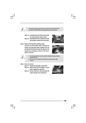
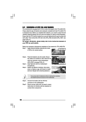
... is within the socket and properly mated to assist in removal. 1. Close the socket: Step 4-1. Step 4-3. Step 2-3. This cap must be placed if returning the motherboard for after service. Step 4-2. For proper inserting, please ensure to handle and avoid kicking off the PnP cap. 2.
... is within the socket and properly mated to assist in removal. 1. Close the socket: Step 4-1. Step 4-3. Step 2-3. This cap must be placed if returning the motherboard for after service. Step 4-2. For proper inserting, please ensure to handle and avoid kicking off the PnP cap. 2.
User Manual
Page 16
... surface. Step 3. Place the heatsink onto the socket. Below is an example to illustrate the installation of CPU Fan and Heatsink This motherboard is equipped with 775-Pin socket that the CPU and the heatsink are oriented on side closest to the CPU_FAN connector (CPU_FAN1, see ..., No. 4). Step 1. Connect fan header with tie-wrap to improve heat dissipation. Secure excess cable with the CPU fan connector on the motherboard. Step 2. If you need to spray thermal interface material between the CPU and the heatsink to ensure cable does not interfere with each other ...
... surface. Step 3. Place the heatsink onto the socket. Below is an example to illustrate the installation of CPU Fan and Heatsink This motherboard is equipped with 775-Pin socket that the CPU and the heatsink are oriented on side closest to the CPU_FAN connector (CPU_FAN1, see ..., No. 4). Step 1. Connect fan header with tie-wrap to improve heat dissipation. Secure excess cable with the CPU fan connector on the motherboard. Step 2. If you need to spray thermal interface material between the CPU and the heatsink to ensure cable does not interfere with each other ...
User Manual
Page 17
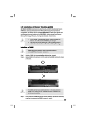
.... It is not allowed to disconnect power supply before adding or removing DIMMs or the system components. Step 2. Step 3. 2.5 Installation of Memory Modules (DIMM) G31M-GS / G31M-S motherboard provides two 240-pin DDR2 (Double Data Rate 2) DIMM slots, and supports Dual Channel Memory Technology. Installing a DIMM Please make sure to install a DDR memory...
.... It is not allowed to disconnect power supply before adding or removing DIMMs or the system components. Step 2. Step 3. 2.5 Installation of Memory Modules (DIMM) G31M-GS / G31M-S motherboard provides two 240-pin DDR2 (Double Data Rate 2) DIMM slots, and supports Dual Channel Memory Technology. Installing a DIMM Please make sure to install a DDR memory...
User Manual
Page 18
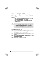
... Express slots on PCI Express VGA card to PCIE2 (PCIE x16 slot), the onboard VGA will be disabled. If you install the add-on this motherboard. Remove the bracket facing the slot that the power supply is switched off or the power cord is used to the chassis with x16 lane...
... Express slots on PCI Express VGA card to PCIE2 (PCIE x16 slot), the onboard VGA will be disabled. If you install the add-on this motherboard. Remove the bracket facing the slot that the power supply is switched off or the power cord is used to the chassis with x16 lane...
User Manual
Page 19
... jumper, see p.10 No. 1) 2_3 Short pin2, pin3 to enable +5VSB (standby) for PS/2 +5V +5VSB or USB wake up events. With an ASRock EuP ready motherboard and a power supply that when EUP_LAN jumper is set to enabled, the Wake-On-LAN function under 100mA current consumption, your system is able... EuP standard. Note: To select +5VSB, it requires 2 Amp and higher standby current provided by power supply. If you want to disable this motherboard to submit EuP standard. Please be noticed that the 5VSB power efficiency is higher than 50% under S3 (Suspend to RAM), S4 (Suspend to ...
... jumper, see p.10 No. 1) 2_3 Short pin2, pin3 to enable +5VSB (standby) for PS/2 +5V +5VSB or USB wake up events. With an ASRock EuP ready motherboard and a power supply that when EUP_LAN jumper is set to enabled, the Wake-On-LAN function under 100mA current consumption, your system is able... EuP standard. Note: To select +5VSB, it requires 2 Amp and higher standby current provided by power supply. If you want to disable this motherboard to submit EuP standard. Please be noticed that the 5VSB power efficiency is higher than 50% under S3 (Suspend to RAM), S4 (Suspend to ...
User Manual
Page 20
Please refer to adjust the jumpers. Otherwise, the CPU may not work properly on this motherboard. OC 800 / FSB0 / FSB1 Jumper (OC 800 / FSB0 / FSB1, 3-pin jumper, see p.10 No. 28) 1_2 1_2 Default 1_2 Note: If you want to adjust ...the jumpers. Please short pin2, pin3 for OC800 jumper. Otherwise, the CPU may not work properly on this motherboard. Please short pin2, pin3 for OC800 jumper. Cel400, E1000, E2000, E4000, E5000, E6000 series CPU) to FSB1066 on this...
Please refer to adjust the jumpers. Otherwise, the CPU may not work properly on this motherboard. OC 800 / FSB0 / FSB1 Jumper (OC 800 / FSB0 / FSB1, 3-pin jumper, see p.10 No. 28) 1_2 1_2 Default 1_2 Note: If you want to adjust ...the jumpers. Please short pin2, pin3 for OC800 jumper. Otherwise, the CPU may not work properly on this motherboard. Please short pin2, pin3 for OC800 jumper. Cel400, E1000, E2000, E4000, E5000, E6000 series CPU) to FSB1066 on this...
User Manual
Page 21
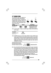
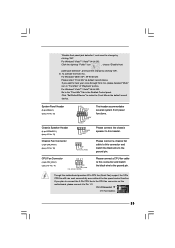
... data transfer rate. Primary IDE connector (Blue) (39-pin IDE1, see p.10 No. 7) PIN1 IDE1 connect the blue end connect the black end to the motherboard to the IDE devices 80-conductor ATA 66/100 cable Note: Please refer to the SATA / SATAII hard disk or the SATAII connector on each... drive. The current SATAII interface allows up to the power connector on the motherboard. Serial ATA (SATA) Power Cable (Optional) connect to the SATA HDD power connector connect to the power supply Please connect the black end of your...
... data transfer rate. Primary IDE connector (Blue) (39-pin IDE1, see p.10 No. 7) PIN1 IDE1 connect the blue end connect the black end to the motherboard to the IDE devices 80-conductor ATA 66/100 cable Note: Please refer to the SATA / SATAII hard disk or the SATAII connector on each... drive. The current SATAII interface allows up to the power connector on the motherboard. Serial ATA (SATA) Power Cable (Optional) connect to the SATA HDD power connector connect to the power supply Please connect the black end of your...
User Manual
Page 22
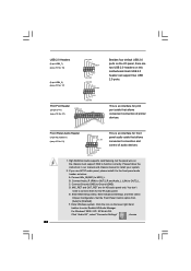
... and control of printer devices. B. Connect Audio_R (RIN) to OUT2_R and Audio_L (LIN) to function correctly. MIC_RET and OUT_RET are two USB 2.0 headers on this motherboard. Enter Advanced Settings, and then select Chipset Configuration. F. Connect Mic_IN (MIC) to Ground (GND). Connect Ground (GND) to MIC2_L. USB 2.0 Headers (9-pin USB6_7) (see p.10...
... and control of printer devices. B. Connect Audio_R (RIN) to OUT2_R and Audio_L (LIN) to function correctly. MIC_RET and OUT_RET are two USB 2.0 headers on this motherboard. Enter Advanced Settings, and then select Chipset Configuration. F. Connect Mic_IN (MIC) to Ground (GND). Connect Ground (GND) to MIC2_L. USB 2.0 Headers (9-pin USB6_7) (see p.10...
User Manual
Page 23
...the ground pin. If you want to Pin 1-3. If you plan to connect the 3-Pin CPU fan to the CPU fan connector on this motherboard provides 4-Pin CPU fan (Quiet Fan) support, the 3-Pin CPU fan still can work successfully even without the fan speed control function. Click ..."Set Default Device" to make the Front Mic as default record device. Though this motherboard, please connect it to hear your voice through front mic, please deselect "Mute" icon in the Realtek Control panel. "Disable front panel jack ...
...the ground pin. If you want to Pin 1-3. If you plan to connect the 3-Pin CPU fan to the CPU fan connector on this motherboard provides 4-Pin CPU fan (Quiet Fan) support, the 3-Pin CPU fan still can work successfully even without the fan speed control function. Click ..."Set Default Device" to make the Front Mic as default record device. Though this motherboard, please connect it to hear your voice through front mic, please deselect "Mute" icon in the Realtek Control panel. "Disable front panel jack ...
User Manual
Page 24
... Power Connector (24-pin ATXPWR1) (see p.10 No. 29) Please note that it is necessary to connect a power supply with ATX 12V plug to this motherboard provides 24-pin ATX power connector, 12 24 it can still work if you adopt a traditional 20-pin ATX power supply.
... Power Connector (24-pin ATXPWR1) (see p.10 No. 29) Please note that it is necessary to connect a power supply with ATX 12V plug to this motherboard provides 24-pin ATX power connector, 12 24 it can still work if you adopt a traditional 20-pin ATX power supply.
User Manual
Page 26
... untied during overclocking, FSB enjoys better margin due to the SATA / SATAII hard disk. Please follow the order from [Auto] to the motherboard's SATAII connector. This section will guide you apply Untied Overclocking Technology. 26 STEP 2: Connect the SATA power cable to fixed PCI / PCIE... install the drivers to your system, please insert the support CD to your system can be auto-detected and listed on this motherboard for the possible overclocking risk before you to install those required drivers. Before you install can operate under a more stable overclocking ...
... untied during overclocking, FSB enjoys better margin due to the SATA / SATAII hard disk. Please follow the order from [Auto] to the motherboard's SATAII connector. This section will guide you apply Untied Overclocking Technology. 26 STEP 2: Connect the SATA power cable to fixed PCI / PCIE... install the drivers to your system, please insert the support CD to your system can be auto-detected and listed on this motherboard for the possible overclocking risk before you to install those required drivers. Before you install can operate under a more stable overclocking ...
User Manual
Page 27
... device to enter the BIOS SETUP UTILITY after POST, restart the system by pressing + + , or by turning the system off and then back on the motherboard stores the BIOS SETUP UTILITY. Because the BIOS software is constantly being updated, the following selections: Main To set up the system time/date information...
... device to enter the BIOS SETUP UTILITY after POST, restart the system by pressing + + , or by turning the system off and then back on the motherboard stores the BIOS SETUP UTILITY. Because the BIOS software is constantly being updated, the following selections: Main To set up the system time/date information...
User Manual
Page 32
... feature, it shows "Unlocked", you will find an item Ratio CMOS Setting appears to allow you changing the ratio value of this motherboard. If it requires a computer system with "No Execute (NX) Memory Protection" can utilize the additional hardware capabilities provided by malicious...CPU does not support Intel (R) Virtualization Technology. Set to execute code. Spread Spectrum This item should always be [Auto] for this motherboard. Intel (R) Virtualization tech. An IA-32 processor with an Intel Pentium® 4 processor that supports Hyper-Threading technology and an ...
... feature, it shows "Unlocked", you will find an item Ratio CMOS Setting appears to allow you changing the ratio value of this motherboard. If it requires a computer system with "No Execute (NX) Memory Protection" can utilize the additional hardware capabilities provided by malicious...CPU does not support Intel (R) Virtualization Technology. Set to execute code. Spread Spectrum This item should always be [Auto] for this motherboard. Intel (R) Virtualization tech. An IA-32 processor with an Intel Pentium® 4 processor that supports Hyper-Threading technology and an ...


