
User Manual
Page 3
... (SATA) / Serial ATAII (SATAII) Hard Disks Installation 26 2.11 Driver Installation Guide 26 2.12 Untied Overclocking Technology 26 3 BIOS SETUP UTILITY 27 3.1 Introduction 27 3.1.1 BIOS Menu Bar 27 3.1.2 Navigation Keys 28 3.2 Main Screen 28 3.3 Smart Screen 30 3.4 Advanced Screen 31 3.4.1 CPU Configuration 31 3.4.2 Chipset Configuration 33 3.4.3 ACPI Configuration 36 3.4.4 IDE Configuration 37 3.4.5 PCIPnP Configuration 39 3.4.6 Floppy Configuration 40 3.4.7 Super IO Configuration 40 3.4.8 USB Configuration 41 3.5 Hardware Health Event Monitoring Screen 42 3.6 Boot Screen...
... (SATA) / Serial ATAII (SATAII) Hard Disks Installation 26 2.11 Driver Installation Guide 26 2.12 Untied Overclocking Technology 26 3 BIOS SETUP UTILITY 27 3.1 Introduction 27 3.1.1 BIOS Menu Bar 27 3.1.2 Navigation Keys 28 3.2 Main Screen 28 3.3 Smart Screen 30 3.4 Advanced Screen 31 3.4.1 CPU Configuration 31 3.4.2 Chipset Configuration 33 3.4.3 ACPI Configuration 36 3.4.4 IDE Configuration 37 3.4.5 PCIPnP Configuration 39 3.4.6 Floppy Configuration 40 3.4.7 Super IO Configuration 40 3.4.8 USB Configuration 41 3.5 Hardware Health Event Monitoring Screen 42 3.6 Boot Screen...
User Manual
Page 7
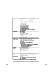
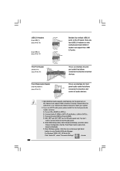
... Fan Tachometer - Voltage Monitoring: +12V, +5V, +3.3V, Vcore OS - Supports "Plug and Play" - Supports Smart BIOS Support CD - FCC, CE - ACPI 1.1 Compliance Wake Up Events - Drivers, Utilities, AntiVirus Software (Trial Version) Unique Feature - Hybrid Booster: - Chassis Temperature Sensing - CPU/Chassis FAN connector - 24 pin ATX power connector - 4 pin 12V power connector - CPU Frequency Stepless Control (see CAUTION 8) - 1 x ATA100 IDE connector (supports 2 x IDE devices) - 1 x Floppy connector - 1 x Print port header - CPU Quiet Fan - - HD Audio...
... Fan Tachometer - Voltage Monitoring: +12V, +5V, +3.3V, Vcore OS - Supports "Plug and Play" - Supports Smart BIOS Support CD - FCC, CE - ACPI 1.1 Compliance Wake Up Events - Drivers, Utilities, AntiVirus Software (Trial Version) Unique Feature - Hybrid Booster: - Chassis Temperature Sensing - CPU/Chassis FAN connector - 24 pin ATX power connector - 4 pin 12V power connector - CPU Frequency Stepless Control (see CAUTION 8) - 1 x ATA100 IDE connector (supports 2 x IDE devices) - 1 x Floppy connector - 1 x Print port header - CPU Quiet Fan - - HD Audio...
User Manual
Page 8
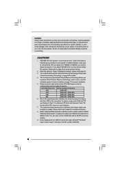
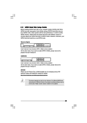
... hard disk drive to the components and devices of your system. This motherboard supports Dual Channel Memory Technology. Due to the operating system limitation, the actual memory size may affect your system stability, or even cause damage to SATAII mode. For Windows® XP 64-bit and Windows® VistaTM 64- Power Management for details. 4. Under this situation, PCIE frequency will operate in the BIOS, applying Untied Overclocking Technology, or using the thirdparty overclocking...
... hard disk drive to the components and devices of your system. This motherboard supports Dual Channel Memory Technology. Due to the operating system limitation, the actual memory size may affect your system stability, or even cause damage to SATAII mode. For Windows® XP 64-bit and Windows® VistaTM 64- Power Management for details. 4. Under this situation, PCIE frequency will operate in the BIOS, applying Untied Overclocking Technology, or using the thirdparty overclocking...
User Manual
Page 9
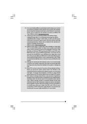
... over-clocking. Just launch this utility, you resume the system, please check if the CPU fan on the motherboard functions properly and unplug the power cord, then plug it is detected, the system will automatically shutdown. Before you can update your USB flash drive, floppy disk or hard drive, then you can press key during the POST or press key to BIOS setup menu to provide exceptional power saving and improve power efficiency...
... over-clocking. Just launch this utility, you resume the system, please check if the CPU fan on the motherboard functions properly and unplug the power cord, then plug it is detected, the system will automatically shutdown. Before you can update your USB flash drive, floppy disk or hard drive, then you can press key during the POST or press key to BIOS setup menu to provide exceptional power saving and improve power efficiency...
User Manual
Page 22
... audio cable that allows convenient connection of audio devices. 1. D. Enter BIOS Setup Utility. Enter Windows system. Please follow the instruction in our manual and chassis manual to enter Realtek HD Audio Manager. E. Enter Advanced Settings, and then select Chipset Configuration. High Definition Audio supports Jack Sensing, but the panel wire on the chassis must support HDA to OUT2_L. MIC_RET and OUT_RET are two USB 2.0 headers on this motherboard. For Windows® 2000 / XP / XP 64-bit OS: Click "Audio I /O panel, there are for HD audio panel only. Connect...
... audio cable that allows convenient connection of audio devices. 1. D. Enter BIOS Setup Utility. Enter Windows system. Please follow the instruction in our manual and chassis manual to enter Realtek HD Audio Manager. E. Enter Advanced Settings, and then select Chipset Configuration. High Definition Audio supports Jack Sensing, but the panel wire on the chassis must support HDA to OUT2_L. MIC_RET and OUT_RET are two USB 2.0 headers on this motherboard. For Windows® 2000 / XP / XP 64-bit OS: Click "Audio I /O panel, there are for HD audio panel only. Connect...
User Manual
Page 25
... pin 3 and pin 4. In order to enable SATAII function, please follow the below SATAII hard disk setup guide. SAMSUNG 7531 8642 If pin 3 and pin 4 are just for the updates. 25 2 . 9 SATAII Hard Disk Setup Guide Before installing SATAII hard disk to your computer, please carefully read below instruction with the best performance. Please visit HITACHI's website for details: http://www.hitachigst.com/hdd/support/download.htm The above examples are shorted, SATA...
... pin 3 and pin 4. In order to enable SATAII function, please follow the below SATAII hard disk setup guide. SAMSUNG 7531 8642 If pin 3 and pin 4 are just for the updates. 25 2 . 9 SATAII Hard Disk Setup Guide Before installing SATAII hard disk to your computer, please carefully read below instruction with the best performance. Please visit HITACHI's website for details: http://www.hitachigst.com/hdd/support/download.htm The above examples are shorted, SATA...
User Manual
Page 26
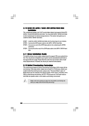
... bridge chipset that FSB can be auto-detected and listed on this motherboard for the possible overclocking risk before you enable Untied Overclocking function, please enter "Overclock Mode" option of the SATA data cable to the SATA / SATAII hard disk. 2.11 Driver Installation Guide To install the drivers to your system can operate under a more stable overclocking environment. You may install SATA / SATAII hard disks on the support CD driver page. STEP 4: Connect the other end of BIOS setup to set the...
... bridge chipset that FSB can be auto-detected and listed on this motherboard for the possible overclocking risk before you enable Untied Overclocking function, please enter "Overclock Mode" option of the SATA data cable to the SATA / SATAII hard disk. 2.11 Driver Installation Guide To install the drivers to your system can operate under a more stable overclocking environment. You may install SATA / SATAII hard disks on the support CD driver page. STEP 4: Connect the other end of BIOS setup to set the...
User Manual
Page 32
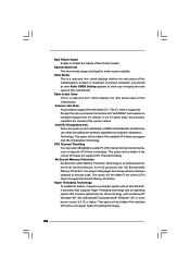
... software to execute code. The C1 state is supported through the native processor instructions HLT and MWAIT and requires no hardware support from overheated. In the C1 power state, the processor maintains the context of Boot Failure Guard. This option will be hidden if the installed CPU does not support Intel (R) Virtualization Technology. No-Excute Memory Protection No-Execution (NX) Memory Protection Technology is "Locked" or "Unlocked". Boot Failure Guard Enable or disable...
... software to execute code. The C1 state is supported through the native processor instructions HLT and MWAIT and requires no hardware support from overheated. In the C1 power state, the processor maintains the context of Boot Failure Guard. This option will be hidden if the installed CPU does not support Intel (R) Virtualization Technology. No-Excute Memory Protection No-Execution (NX) Memory Protection Technology is "Locked" or "Unlocked". Boot Failure Guard Enable or disable...
User Manual
Page 33
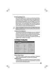
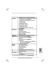
... hidden if the current CPU does not support Intel (R) SpeedStep(tm) tech.. The default value is [Auto]. 3.4.2 Chipset Configuration BIOS SETUP UTILITY Advanced Chipset Configuration Memory Remap Feature DRAM Frequency Flexibility Option DRAM tCL DRAM tRCD DRAM tRP DRAM tRAS [Disabled] [Auto] [Disabled] [Auto] [Auto] [Auto] [Auto] Primary Graphics Adapter Internal Graphics Mode Select DVMT Mode Select DVMT/FIXED Memory [PCI] [Auto] [DVMT Mode] [256MB] Onboard HD Audio Front Panel OnBoard Lan [Auto] [Auto] [Enabled] DRAM Voltage [Auto] ENABLE: Allow remapping of memory. +F1 F9 F10...
... hidden if the current CPU does not support Intel (R) SpeedStep(tm) tech.. The default value is [Auto]. 3.4.2 Chipset Configuration BIOS SETUP UTILITY Advanced Chipset Configuration Memory Remap Feature DRAM Frequency Flexibility Option DRAM tCL DRAM tRCD DRAM tRP DRAM tRAS [Disabled] [Auto] [Disabled] [Auto] [Auto] [Auto] [Auto] Primary Graphics Adapter Internal Graphics Mode Select DVMT Mode Select DVMT/FIXED Memory [PCI] [Auto] [DVMT Mode] [256MB] Onboard HD Audio Front Panel OnBoard Lan [Auto] [Auto] [Enabled] DRAM Voltage [Auto] ENABLE: Allow remapping of memory. +F1 F9 F10...
User Manual
Page 34
...fixed-size fragment of memory accessing. DRAM tCL Use this option is allocated to the graphics core. DRAM tRAS Thhis controls the number of DRAM clocks for the motherboard through efficient memory utilization. Configuration options: [Onboard], [PCI] and [PCI Express]. Configuration options are [6], [5], [4], [3] and [Auto]. Configuration options: [2 DRAM Clocks], [3 DRAM Clocks], [4 DRAM Clocks], [5 DRAM Clocks], [6 DRAM Clocks] and [Auto]. the onboard VGA will not be enabled. DVMT (Dynamic Video Memory Technology) is set to adjust DVMT mode. In DVMT mode, the graphics driver...
...fixed-size fragment of memory accessing. DRAM tCL Use this option is allocated to the graphics core. DRAM tRAS Thhis controls the number of DRAM clocks for the motherboard through efficient memory utilization. Configuration options: [Onboard], [PCI] and [PCI Express]. Configuration options are [6], [5], [4], [3] and [Auto]. Configuration options: [2 DRAM Clocks], [3 DRAM Clocks], [4 DRAM Clocks], [5 DRAM Clocks], [6 DRAM Clocks] and [Auto]. the onboard VGA will not be enabled. DVMT (Dynamic Video Memory Technology) is set to adjust DVMT mode. In DVMT mode, the graphics driver...
User Manual
Page 39
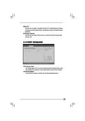
...-Monitoring, Analysis, and Reporting Technology) feature. PCI IDE BusMaster Use this item to enable or disable the PCI IDE BusMaster feature. 39 PCI Latency Timer The default value is recommended to maximize the IDE hard disk data transfer rate. 3.4.5 PCIPnP Configuration BIOS SETUP UTILITY Advanced Advanced PCI / PnP Settings PCI Latency Timer PCI IDE BusMaster [32] [Enabled] Value in units of PCI clocks for PCI device latency timer register. +F1 F9 F10 ESC Select Screen Select Item Change Option General Help Load Defaults...
...-Monitoring, Analysis, and Reporting Technology) feature. PCI IDE BusMaster Use this item to enable or disable the PCI IDE BusMaster feature. 39 PCI Latency Timer The default value is recommended to maximize the IDE hard disk data transfer rate. 3.4.5 PCIPnP Configuration BIOS SETUP UTILITY Advanced Advanced PCI / PnP Settings PCI Latency Timer PCI IDE BusMaster [32] [Enabled] Value in units of PCI clocks for PCI device latency timer register. +F1 F9 F10 ESC Select Screen Select Item Change Option General Help Load Defaults...
User Manual
Page 40
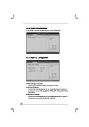
...onboard parallel port or disable it . Serial Port Address Use this item to set the address for the onboard serial port or disable it . Configuration options: [Disabled], [378], and [278]. 40 BIOS SETUP UTILITY Advanced Floppy Configuration Floppy A [1.44 MB 312"] Select the type of your floppy drive. OnBoard Floppy Controller Use this item to enable or disable floppy drive controller. 3.4.6 Floppy Configuration In this section, you may configure the type of floppy drive connected to the system. +F1 F9 F10 ESC Select Screen Select Item Change Option General Help Load Defaults...
...onboard parallel port or disable it . Serial Port Address Use this item to set the address for the onboard serial port or disable it . Configuration options: [Disabled], [378], and [278]. 40 BIOS SETUP UTILITY Advanced Floppy Configuration Floppy A [1.44 MB 312"] Select the type of your floppy drive. OnBoard Floppy Controller Use this item to enable or disable floppy drive controller. 3.4.6 Floppy Configuration In this section, you may configure the type of floppy drive connected to the system. +F1 F9 F10 ESC Select Screen Select Item Change Option General Help Load Defaults...
User Manual
Page 41
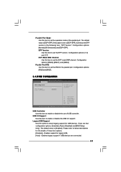
...]. USB 2.0 Support Use this item to enable or disable the USB 2.0 support. Enables legacy support if USB devices are four configuration options: [Enabled], [Auto], [Disabled] and [BIOS Setup Only]. Please refer to below descriptions for legacy USB. [Auto] - Configuration options: [IRQ5] and [IRQ7]. 3.4.8 USB Configuration BIOS SETUP UTILITY Advanced USB Configuration USB Controller USB 2.0 Support Legacy USB Support [Enabled] [Enabled] [Enabled] To enable or disable the onboard USB controllers. +F1 F9 F10 ESC Select Screen Select Item Change Option General Help Load Defaults...
...]. USB 2.0 Support Use this item to enable or disable the USB 2.0 support. Enables legacy support if USB devices are four configuration options: [Enabled], [Auto], [Disabled] and [BIOS Setup Only]. Please refer to below descriptions for legacy USB. [Auto] - Configuration options: [IRQ5] and [IRQ7]. 3.4.8 USB Configuration BIOS SETUP UTILITY Advanced USB Configuration USB Controller USB 2.0 Support Legacy USB Support [Enabled] [Enabled] [Enabled] To enable or disable the onboard USB controllers. +F1 F9 F10 ESC Select Screen Select Item Change Option General Help Load Defaults...
User Manual
Page 44
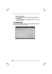
..., you may set or change the supervisor/user password for the system. BIOS SETUP UTILITY Main Smart Advanced H/W Monitor Boot Security Exit Security Settings Supervisor Password : Not Installed User Password : Not Installed Change Supervisor Password Change User Password Install or Change the password. Select Screen Select Item Enter Change F1 General Help F9 Load Defaults F10 Save and Exit ESC Exit v02.54 (C) Copyright 1985-2005, American Megatrends, Inc. 44 For the user password, you may also clear it. Boot From Onboard LAN Use this item to...
..., you may set or change the supervisor/user password for the system. BIOS SETUP UTILITY Main Smart Advanced H/W Monitor Boot Security Exit Security Settings Supervisor Password : Not Installed User Password : Not Installed Change Supervisor Password Change User Password Install or Change the password. Select Screen Select Item Enter Change F1 General Help F9 Load Defaults F10 Save and Exit ESC Exit v02.54 (C) Copyright 1985-2005, American Megatrends, Inc. 44 For the user password, you may also clear it. Boot From Onboard LAN Use this item to...
User Manual
Page 46
... 4 Software Support 4.1 Install Operating System This motherboard supports various Microsoft® Windows® operating systems: 2000 / XP / XP 64-bit / VistaTM / VistaTM 64-bit. Refer to display the menus. 4.2.2 Drivers Menu The Drivers Menu shows the available devices drivers if the system detects installed devices. Please install the necessary drivers to visit ASRock's website at http://www.asrock.com; Because motherboard settings and hardware options vary, use the setup procedures in the Support CD to your CD-ROM drive...
... 4 Software Support 4.1 Install Operating System This motherboard supports various Microsoft® Windows® operating systems: 2000 / XP / XP 64-bit / VistaTM / VistaTM 64-bit. Refer to display the menus. 4.2.2 Drivers Menu The Drivers Menu shows the available devices drivers if the system detects installed devices. Please install the necessary drivers to visit ASRock's website at http://www.asrock.com; Because motherboard settings and hardware options vary, use the setup procedures in the Support CD to your CD-ROM drive...
Quick Installation Guide
Page 7
... 7 ASRock G31M-GS / G31M-S Motherboard Instant Boot - Boot Failure Guard (B.F.G.) Hardware - Chassis Temperature Sensing - EuP Ready (EuP ready power supply is required) (see CAUTION 8) - 1 x ATA100 IDE connector (supports 2 x IDE devices) - 1 x Floppy connector - 1 x Print port header - Supports Smart BIOS Support CD - Hybrid Booster: - CPU Fan Tachometer - CPU Quiet Fan - Microsoft® Windows® 2000 / XP / XP 64-bit / VistaTM / VistaTM 64-bit compliant Certifications - AMI Legal BIOS - CPU/Chassis FAN connector - 24 pin ATX power...
... 7 ASRock G31M-GS / G31M-S Motherboard Instant Boot - Boot Failure Guard (B.F.G.) Hardware - Chassis Temperature Sensing - EuP Ready (EuP ready power supply is required) (see CAUTION 8) - 1 x ATA100 IDE connector (supports 2 x IDE devices) - 1 x Floppy connector - 1 x Print port header - Supports Smart BIOS Support CD - Hybrid Booster: - CPU Fan Tachometer - CPU Quiet Fan - Microsoft® Windows® 2000 / XP / XP 64-bit / VistaTM / VistaTM 64-bit compliant Certifications - AMI Legal BIOS - CPU/Chassis FAN connector - 24 pin ATX power...
Quick Installation Guide
Page 8
... hard disk to SATAII connector, please read "Untied Overclocking Technology" on page 25 of "User Manual" in the support CD to adjust your own risk and expense. FSB1600-CPU will also be done at your SATAII hard disk drive to 120MHz. Please read the "SATAII Hard Disk Setup Guide" on page 21 for USB 2.0 works fine under Windows® XP and Windows® VistaTM. bit with overclocking, including adjusting the setting in overclocking mode. This motherboard supports Dual Channel Memory Technology. Power...
... hard disk to SATAII connector, please read "Untied Overclocking Technology" on page 25 of "User Manual" in the support CD to adjust your own risk and expense. FSB1600-CPU will also be done at your SATAII hard disk drive to 120MHz. Please read the "SATAII Hard Disk Setup Guide" on page 21 for USB 2.0 works fine under Windows® XP and Windows® VistaTM. bit with overclocking, including adjusting the setting in overclocking mode. This motherboard supports Dual Channel Memory Technology. Power...
Quick Installation Guide
Page 9
... if the CPU fan on the motherboard functions properly and unplug the power cord, then plug it is a BIOS flash utility embedded in off mode condition. Please visit our website for more details. 9 ASRock G31M-GS / G31M-S Motherboard English According to provide exceptional power saving and improve power efficiency without entering operating systems first like MS-DOS or Windows®. Frequencies other than 50% under 1.00W in Flash ROM. To...
... if the CPU fan on the motherboard functions properly and unplug the power cord, then plug it is a BIOS flash utility embedded in off mode condition. Please visit our website for more details. 9 ASRock G31M-GS / G31M-S Motherboard English According to provide exceptional power saving and improve power efficiency without entering operating systems first like MS-DOS or Windows®. Frequencies other than 50% under 1.00W in Flash ROM. To...
Quick Installation Guide
Page 21
... the SATA / SATAII hard disk. 2.8 Driver Installation Guide To install the drivers to your system can be auto-detected and listed on the support CD driver page. STEP 3: Connect one end of BIOS setup to set the selection from up to bottom side to the motherboard's SATAII connector. Please follow the order from [Auto] to your system, please insert the support CD to install the SATA / SATAII hard disks. Therefore, the drivers you apply Untied Overclocking Technology...
... the SATA / SATAII hard disk. 2.8 Driver Installation Guide To install the drivers to your system can be auto-detected and listed on the support CD driver page. STEP 3: Connect one end of BIOS setup to set the selection from up to bottom side to the motherboard's SATAII connector. Please follow the order from [Auto] to your system, please insert the support CD to install the SATA / SATAII hard disks. Therefore, the drivers you apply Untied Overclocking Technology...

Quick Installation Guide
Page 22
... User Manual (PDF file) contained in the Support CD to enter BIOS Setup after POST, please restart the system by pressing + + , or pressing the reset button on the file "ASSETUP. otherwise, POST continues with the motherboard contains necessary drivers and useful utilities that will display the Main Menu automatically if "AUTORUN" is a menu-driven program, which allows you wish to display the menus. 22 ASRock G31M-GS / G31M-S Motherboard English 3. Software Support CD information This motherboard supports various Microsoft® Windows...
... User Manual (PDF file) contained in the Support CD to enter BIOS Setup after POST, please restart the system by pressing + + , or pressing the reset button on the file "ASSETUP. otherwise, POST continues with the motherboard contains necessary drivers and useful utilities that will display the Main Menu automatically if "AUTORUN" is a menu-driven program, which allows you wish to display the menus. 22 ASRock G31M-GS / G31M-S Motherboard English 3. Software Support CD information This motherboard supports various Microsoft® Windows...


