User Manual
Page 1
All rights reserved. 1 G Pro / GV Pro User Manual Published October 2002 Copyright©2002 ASRock INC.
All rights reserved. 1 G Pro / GV Pro User Manual Published October 2002 Copyright©2002 ASRock INC.
User Manual
Page 3
Boot Menu 24 5. Exit Menu 24 3 Advanced Menu 20 2. Security Menu 22 3. Power Menu 23 4. Contents 1 Introduction 4 1.1 Package Contents 4 1.2 Specifications 4 1.3 Motherboard Layout (G Pro 6 1.4 Motherboard Layout (GV Pro 7 1.5 ASRock I/OTM (G Pro / GV Pro 8 2 Installation 9 2.1 Screw Holes 9 2.2 Pre-installation Precautions 9 2.3 CPU Installation 9 2.4 Installation of Heatsink and CPU fan 10 2.5 Installation of Memory Modules (DIMM 10 2.6 Expansion Slots 11 2.7 Jumpers ...
Boot Menu 24 5. Exit Menu 24 3 Advanced Menu 20 2. Security Menu 22 3. Power Menu 23 4. Contents 1 Introduction 4 1.1 Package Contents 4 1.2 Specifications 4 1.3 Motherboard Layout (G Pro 6 1.4 Motherboard Layout (GV Pro 7 1.5 ASRock I/OTM (G Pro / GV Pro 8 2 Installation 9 2.1 Screw Holes 9 2.2 Pre-installation Precautions 9 2.3 CPU Installation 9 2.4 Installation of Heatsink and CPU fan 10 2.5 Installation of Memory Modules (DIMM 10 2.6 Expansion Slots 11 2.7 Jumpers ...
User Manual
Page 4
..., the Appendix offers more advanced BIOS setup information. 1.1 Package Contents ASRock G Pro or GV Pro motherboard (Micro ATX form factor: 9.6" x 9.6", 24.4 x 24.4 cm) ASRock G Pro / GV Pro Quick Installation Guide ASRock Intel-SiS Support CD 1 cable for IDE devices (1 x ATA 66/100/133) 1 cable for floppy drive (1 x ribbon cable) 1 ASRock I/O shield 1 COM port bracket 1.2 Specifications Platform: CPU: Chipsets: Clock Generator...
..., the Appendix offers more advanced BIOS setup information. 1.1 Package Contents ASRock G Pro or GV Pro motherboard (Micro ATX form factor: 9.6" x 9.6", 24.4 x 24.4 cm) ASRock G Pro / GV Pro Quick Installation Guide ASRock Intel-SiS Support CD 1 cable for IDE devices (1 x ATA 66/100/133) 1 cable for floppy drive (1 x ribbon cable) 1 ASRock I/O shield 1 COM port bracket 1.2 Specifications Platform: CPU: Chipsets: Clock Generator...
User Manual
Page 5
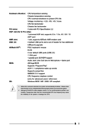
Please check if the CPU fan on the motherboard functions properly before you resume the system. 2. Although G Pro/GV Pro offers stepless control, it is detected, the system will automatically shutdown. Hardware Monitor: CPU temperature sensing Chassis temperature sensing CPU ... shutdown to perform over clocking. Frequencies other than the recommended CPU bus frequency may cause the instability of header for two additional USB ports upgrade ASRock I/OTM: PS/2: keyboard / mouse RJ 45 4 rear default USB ports (USB 2.0) 1 VGA port 1 parallel port: ECP/EPP support Audio Jack: Line...
Please check if the CPU fan on the motherboard functions properly before you resume the system. 2. Although G Pro/GV Pro offers stepless control, it is detected, the system will automatically shutdown. Hardware Monitor: CPU temperature sensing Chassis temperature sensing CPU ... shutdown to perform over clocking. Frequencies other than the recommended CPU bus frequency may cause the instability of header for two additional USB ports upgrade ASRock I/OTM: PS/2: keyboard / mouse RJ 45 4 rear default USB ports (USB 2.0) 1 VGA port 1 parallel port: ECP/EPP support Audio Jack: Line...
User Manual
Page 7
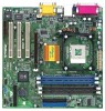
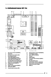
1.4 Motherboard Layout (GV Pro) 22 3 21 45 6 24.4cm (9.6 in) PS/2 Mouse PS/2 Keyboard CPU_FAN1 1 PS2_USB_PWR1 ATX PWR1 PARALLEL PORT PGA478B DDR DIMM1 (64/72 bit, 184-pin module) ... LAN PHY AUX1 CD1 8 7 SiS 650 Series Chipset 01 23 01 23 20 AUDIO1 19 AUDIO CODEC Super I/O PCI 1 PCI 2 11 2MB PCI 3 BIOS AMR1 GV PRO SiS South Bridge CMOS 9 Battery CHA_FAN1 CLRCMOS1 FLOPPY1 IR1 COM1 USB45 SPEAKER1 RESET HDLED PANEL1 PWRBTN PLED 10 14 15 12 26 1 ATX power connector...
1.4 Motherboard Layout (GV Pro) 22 3 21 45 6 24.4cm (9.6 in) PS/2 Mouse PS/2 Keyboard CPU_FAN1 1 PS2_USB_PWR1 ATX PWR1 PARALLEL PORT PGA478B DDR DIMM1 (64/72 bit, 184-pin module) ... LAN PHY AUX1 CD1 8 7 SiS 650 Series Chipset 01 23 01 23 20 AUDIO1 19 AUDIO CODEC Super I/O PCI 1 PCI 2 11 2MB PCI 3 BIOS AMR1 GV PRO SiS South Bridge CMOS 9 Battery CHA_FAN1 CLRCMOS1 FLOPPY1 IR1 COM1 USB45 SPEAKER1 RESET HDLED PANEL1 PWRBTN PLED 10 14 15 12 26 1 ATX power connector...
User Manual
Page 9
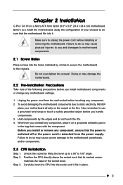
... 1. Do not over-tighten the screws! Whenever you and damages to the chassis. Doing so may cause severe damage to 100o angle. Step 3. Chapter 2 Installation G Pro / GV Pro is detached from the wall socket before touching any component. 2. Step 2. Before you install motherboard components or change any motherboard settings. 1.
... 1. Do not over-tighten the screws! Whenever you and damages to the chassis. Doing so may cause severe damage to 100o angle. Step 3. Chapter 2 Installation G Pro / GV Pro is detached from the wall socket before touching any component. 2. Step 2. Before you install motherboard components or change any motherboard settings. 1.

User Manual
Page 11
...DIMM slot by pressing the retaining clips outward. Additionally, there is completely seated on both G Pro and GV Pro motherboards. AMR slot: AMR slot is used to the chassis with v.92 Modem functionality. The ASRock AGP slot has a special locking mechanism which can securely fasten the graphics card inserted. Remove ... you intend to use . Step 3. Remove the bracket facing the slot that the notch on the DIMM matches the break on G Pro. Replace the system cover. 11 Step 2. Before installing the expansion card, read the documentation of the expansion card and make necessary hardware...
...DIMM slot by pressing the retaining clips outward. Additionally, there is completely seated on both G Pro and GV Pro motherboards. AMR slot: AMR slot is used to the chassis with v.92 Modem functionality. The ASRock AGP slot has a special locking mechanism which can securely fasten the graphics card inserted. Remove ... you intend to use . Step 3. Remove the bracket facing the slot that the notch on the DIMM matches the break on G Pro. Replace the system cover. 11 Step 2. Before installing the expansion card, read the documentation of the expansion card and make necessary hardware...