User Manual
Page 3
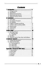
...(G Pro 6 1.4 Motherboard Layout (GV Pro 7 1.5 ASRock I/OTM (G Pro / GV Pro 8 2 Installation 9 2.1 Screw Holes 9 2.2 Pre-installation Precautions 9 2.3 CPU Installation 9 2.4 Installation of Heatsink and CPU fan 10 2.5 Installation of Memory Modules (DIMM 10 2.6 Expansion Slots 11 2.7 Jumpers Setup 12 2.8 Connectors 12 3 BIOS Setup 15 3.1 BIOS Setup Program 15 3.1.1 BIOS Menu... Drivers Menu 19 4.2.3 Utilities Menu 19 4.2.4 Contact Information 19 Appendix: Advanced BIOS Setup 20 1. Boot Menu 24 5. Advanced Menu 20 2. Security Menu 22 3. Power Menu 23 4. Exit Menu 24 3
...(G Pro 6 1.4 Motherboard Layout (GV Pro 7 1.5 ASRock I/OTM (G Pro / GV Pro 8 2 Installation 9 2.1 Screw Holes 9 2.2 Pre-installation Precautions 9 2.3 CPU Installation 9 2.4 Installation of Heatsink and CPU fan 10 2.5 Installation of Memory Modules (DIMM 10 2.6 Expansion Slots 11 2.7 Jumpers Setup 12 2.8 Connectors 12 3 BIOS Setup 15 3.1 BIOS Setup Program 15 3.1.1 BIOS Menu... Drivers Menu 19 4.2.3 Utilities Menu 19 4.2.4 Contact Information 19 Appendix: Advanced BIOS Setup 20 1. Boot Menu 24 5. Advanced Menu 20 2. Security Menu 22 3. Power Menu 23 4. Exit Menu 24 3
User Manual
Page 4
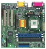
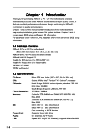
...; processor North Bridge: SiS 650 series chipsets; For advanced users' reference, the Appendix offers more advanced BIOS setup information. 1.1 Package Contents ASRock G Pro or GV Pro motherboard (Micro ATX form factor: 9.6" x 9.6", 24.4 x 24.4 cm) ASRock G Pro / GV Pro Quick Installation Guide ASRock Intel-SiS Support CD 1 cable for IDE devices (1 x ATA 66/100/133) 1 cable for floppy drive...
...; processor North Bridge: SiS 650 series chipsets; For advanced users' reference, the Appendix offers more advanced BIOS setup information. 1.1 Package Contents ASRock G Pro or GV Pro motherboard (Micro ATX form factor: 9.6" x 9.6", 24.4 x 24.4 cm) ASRock G Pro / GV Pro Quick Installation Guide ASRock Intel-SiS Support CD 1 cable for IDE devices (1 x ATA 66/100/133) 1 cable for floppy drive...
User Manual
Page 5
...EPP support Audio Jack: Line Out/ Line In/ Microphone + Game port BIOS: AMI legal BIOS Supports "Plug and Play" ACPI 1.1 compliance wake up events Supports jumperfree SMBIOS 2.3.1 support CPU frequency stepless control (only for G Pro only): 1 universal AGP slot, supports 3.3v / 1.5v, 4X / ...2X / 1X AGP card AMR slot: 1 slot, supports ASRock AMR modem card USB ...
...EPP support Audio Jack: Line Out/ Line In/ Microphone + Game port BIOS: AMI legal BIOS Supports "Plug and Play" ACPI 1.1 compliance wake up events Supports jumperfree SMBIOS 2.3.1 support CPU frequency stepless control (only for G Pro only): 1 universal AGP slot, supports 3.3v / 1.5v, 4X / ...2X / 1X AGP card AMR slot: 1 slot, supports ASRock AMR modem card USB ...
User Manual
Page 7
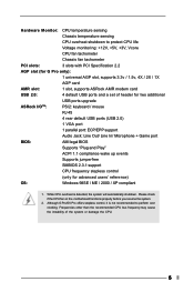
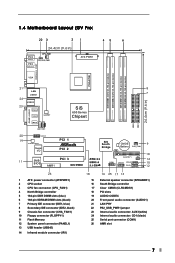
1.4 Motherboard Layout (GV Pro) 22 3 21 45 6 24.4cm (9.6 in) PS/2 Mouse PS/2 Keyboard CPU_FAN1 1 PS2_USB_PWR1 ATX PWR1 PARALLEL PORT PGA478B DDR DIMM1 (64/72 bit, 184-pin module) ... in LAN PHY AUX1 CD1 8 7 SiS 650 Series Chipset 01 23 01 23 20 AUDIO1 19 AUDIO CODEC Super I/O PCI 1 PCI 2 11 2MB PCI 3 BIOS AMR1 GV PRO SiS South Bridge CMOS 9 Battery CHA_FAN1 CLRCMOS1 FLOPPY1 IR1 COM1 USB45 SPEAKER1 RESET HDLED PANEL1 PWRBTN PLED 10 14 15 12 26 1 ATX power...
1.4 Motherboard Layout (GV Pro) 22 3 21 45 6 24.4cm (9.6 in) PS/2 Mouse PS/2 Keyboard CPU_FAN1 1 PS2_USB_PWR1 ATX PWR1 PARALLEL PORT PGA478B DDR DIMM1 (64/72 bit, 184-pin module) ... in LAN PHY AUX1 CD1 8 7 SiS 650 Series Chipset 01 23 01 23 20 AUDIO1 19 AUDIO CODEC Super I/O PCI 1 PCI 2 11 2MB PCI 3 BIOS AMR1 GV PRO SiS South Bridge CMOS 9 Battery CHA_FAN1 CLRCMOS1 FLOPPY1 IR1 COM1 USB45 SPEAKER1 RESET HDLED PANEL1 PWRBTN PLED 10 14 15 12 26 1 ATX power...
User Manual
Page 15
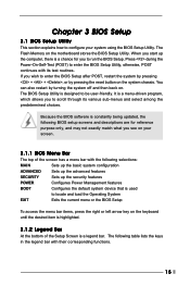
... is a legend bar. Press during the Power-On-Self-Test (POST) to locate and load the Operating System EXIT Exits the current menu or the BIOS Setup To access the menu bar items, press the right or left arrow key on the system chassis. When you start up the computer, there... is a chance for reference purpose only, and may not exactly match what you to enter the BIOS Setup after POST, restart the system by pressing + + , or by turning the system off and then back on the motherboard stores the...
... is a legend bar. Press during the Power-On-Self-Test (POST) to locate and load the Operating System EXIT Exits the current menu or the BIOS Setup To access the menu bar items, press the right or left arrow key on the system chassis. When you start up the computer, there... is a chance for reference purpose only, and may not exactly match what you to enter the BIOS Setup after POST, restart the system by pressing + + , or by turning the system off and then back on the motherboard stores the...
User Manual
Page 16
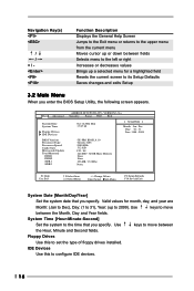
... for month, day, and year are Month: (Jan to Dec), Day: (1 to 31), Year: (up to 2099). Dec Day: 01 - 31 Year: 1980 - 2099 GE-PRO BIOS L0.10 Generic-X86 2000 MHz 512 KB F23 / 08 224 MB + 32 MB Share Memory None None 256 MB / 133 Mhz None F1:Help... Defaults F10:Save & Exit System Date [Month/Day/Year] Set the system date that you enter the BIOS Setup Utility, the following screen appears. Main Advanced System Date System Time Floppy Drives IDE Devices BIOS Version Processor Type Processor Speed Cache Size Microcode Update Total Memory DDR1 DDR2 SDR1 SDR2 AMIBIOS SETUP...
... for month, day, and year are Month: (Jan to Dec), Day: (1 to 31), Year: (up to 2099). Dec Day: 01 - 31 Year: 1980 - 2099 GE-PRO BIOS L0.10 Generic-X86 2000 MHz 512 KB F23 / 08 224 MB + 32 MB Share Memory None None 256 MB / 133 Mhz None F1:Help... Defaults F10:Save & Exit System Date [Month/Day/Year] Set the system date that you enter the BIOS Setup Utility, the following screen appears. Main Advanced System Date System Time Floppy Drives IDE Devices BIOS Version Processor Type Processor Speed Cache Size Microcode Update Total Memory DDR1 DDR2 SDR1 SDR2 AMIBIOS SETUP...
User Manual
Page 17
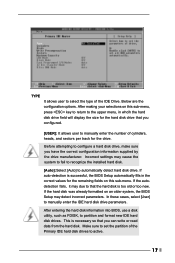
.... In these cases, select [User] to partition and format new IDE hard disk drives. This is necessary so that the hard disk is successful, the BIOS Setup automatically fills in whcih the hard disk drive field will display the size for the hard disk drive that you configured. [USER]: It allows... on this sub-menu. If auto-detection is too old or too new. If the hard disk was already formatted on an older system, the BIOS Setup may cause the system to fail to recognize the installed hard disk. [Auto]:Select [Auto] to automatically detect hard disk drive. Below are the...
.... In these cases, select [User] to partition and format new IDE hard disk drives. This is necessary so that the hard disk is successful, the BIOS Setup automatically fills in whcih the hard disk drive field will display the size for the hard disk drive that you configured. [USER]: It allows... on this sub-menu. If auto-detection is too old or too new. If the hard disk was already formatted on an older system, the BIOS Setup may cause the system to fail to recognize the installed hard disk. [Auto]:Select [Auto] to automatically detect hard disk drive. Below are the...
User Manual
Page 18
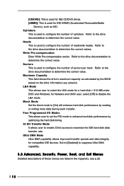
.... [CD/DVD]: This is used for IDE CD/DVD drives. [ARMD]: This is used for IDE ARMD (Accelerated RemovableMedia Device), such as calculated by the BIOS based on the drive information you entered. Write Pre-compensation Enter Write Pre-compensation sector. Fast Programmed I/O Modes This allows user to set the PIO...
.... [CD/DVD]: This is used for IDE CD/DVD drives. [ARMD]: This is used for IDE ARMD (Accelerated RemovableMedia Device), such as calculated by the BIOS based on the drive information you entered. Write Pre-compensation Enter Write Pre-compensation sector. Fast Programmed I/O Modes This allows user to set the PIO...
User Manual
Page 20
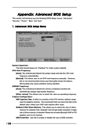
... inserted and automatically assigns appropriate frequency. [Other values]: This allows user to set CPU host frequency manually. Onboard VGA will introduce you the following BIOS Setup menus: "Advanced," "Security," "Power," "Boot," and "Exit." 1. CPU Host Frequency: [Auto]: The motherboard detects the jumper setup and...to a section of the PCI memory address range used for graphics memory. Wrong setup may cause problems during operation. Appendix: Advanced BIOS Setup This section will get better resolution if larger size of share memory is selected. We recommend that you to select the ...
... inserted and automatically assigns appropriate frequency. [Other values]: This allows user to set CPU host frequency manually. Onboard VGA will introduce you the following BIOS Setup menus: "Advanced," "Security," "Power," "Boot," and "Exit." 1. CPU Host Frequency: [Auto]: The motherboard detects the jumper setup and...to a section of the PCI memory address range used for graphics memory. Wrong setup may cause problems during operation. Appendix: Advanced BIOS Setup This section will get better resolution if larger size of share memory is selected. We recommend that you to select the ...
User Manual
Page 23
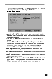
... selected, you must fill the RTC Alarm Date / Hour / Minute / Second sub-fields with the actual wake up and BIOS setup. 3. If [Always] option is selected, the "Password Check" is performed before BIOS setup. Repost Video on S3 resume. If [Power On] is selected, the AC power resumes and the system starts...
... selected, you must fill the RTC Alarm Date / Hour / Minute / Second sub-fields with the actual wake up and BIOS setup. 3. If [Always] option is selected, the "Password Check" is performed before BIOS setup. Repost Video on S3 resume. If [Power On] is selected, the AC power resumes and the system starts...

User Manual
Page 25
.... If you press , it will be restored. All changes are discarded. 25 If you press , original values will save the current settings and exit the BIOS SETUP Utility. If you press , you enter the sub-menu, the message "Load setup original values" will exit the...
.... If you press , it will be restored. All changes are discarded. 25 If you press , original values will save the current settings and exit the BIOS SETUP Utility. If you press , you enter the sub-menu, the message "Load setup original values" will exit the...


