User Manual
Page 3
... 4 1.2 Specifications 4 1.3 Motherboard Layout (G Pro 6 1.4 Motherboard Layout (GV Pro 7 1.5 ASRock I/OTM (G Pro / GV Pro 8 2 Installation 9 2.1 Screw Holes 9 2.2 Pre-installation Precautions 9 2.3 CPU Installation 9 2.4 Installation of Heatsink and CPU fan 10 2.5 Installation of Memory Modules (DIMM 10 2.6 Expansion Slots 11 2.7 Jumpers Setup 12 2.8 Connectors 12 3 BIOS Setup 15 3.1 BIOS Setup Program 15 3.1.1 BIOS Menu Bar 15 3.1.2 Legend Bar 15 3.2 Main Menu 16 3.3 Advanced, Security, Power, Boot, and Exit Menus ..... 18 4 Software Support 19 4.1 Installing Operating...
... 4 1.2 Specifications 4 1.3 Motherboard Layout (G Pro 6 1.4 Motherboard Layout (GV Pro 7 1.5 ASRock I/OTM (G Pro / GV Pro 8 2 Installation 9 2.1 Screw Holes 9 2.2 Pre-installation Precautions 9 2.3 CPU Installation 9 2.4 Installation of Heatsink and CPU fan 10 2.5 Installation of Memory Modules (DIMM 10 2.6 Expansion Slots 11 2.7 Jumpers Setup 12 2.8 Connectors 12 3 BIOS Setup 15 3.1 BIOS Setup Program 15 3.1.1 BIOS Menu Bar 15 3.1.2 Legend Bar 15 3.2 Main Menu 16 3.3 Advanced, Security, Power, Boot, and Exit Menus ..... 18 4 Software Support 19 4.1 Installing Operating...
User Manual
Page 4
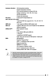
... BIOS setup information. 1.1 Package Contents ASRock G Pro or GV Pro motherboard (Micro ATX form factor: 9.6" x 9.6", 24.4 x 24.4 cm) ASRock G Pro / GV Pro Quick Installation Guide ASRock Intel-SiS Support CD 1 cable for IDE devices (1 x ATA 66/100/133) 1 cable for floppy drive (1 x ribbon cable) 1 ASRock I/O shield 1 COM port bracket 1.2 Specifications Platform: CPU: Chipsets: Clock Generator: Memory: IDE: Floppy Port: Audio: LAN: Micro ATX form factor (9.6" x 9.6", 24.4 x 24.4 cm) Socket 478 for purchasing ASRock G Pro / GV Pro motherboard, a reliable motherboard produced under ASRock...
... BIOS setup information. 1.1 Package Contents ASRock G Pro or GV Pro motherboard (Micro ATX form factor: 9.6" x 9.6", 24.4 x 24.4 cm) ASRock G Pro / GV Pro Quick Installation Guide ASRock Intel-SiS Support CD 1 cable for IDE devices (1 x ATA 66/100/133) 1 cable for floppy drive (1 x ribbon cable) 1 ASRock I/O shield 1 COM port bracket 1.2 Specifications Platform: CPU: Chipsets: Clock Generator: Memory: IDE: Floppy Port: Audio: LAN: Micro ATX form factor (9.6" x 9.6", 24.4 x 24.4 cm) Socket 478 for purchasing ASRock G Pro / GV Pro motherboard, a reliable motherboard produced under ASRock...
User Manual
Page 5
... upgrade ASRock I/OTM: PS/2: keyboard / mouse RJ 45 4 rear default USB ports (USB 2.0) 1 VGA port 1 parallel port: ECP/EPP support Audio Jack: Line Out/ Line In/ Microphone + Game port BIOS: AMI legal BIOS Supports "Plug and Play" ACPI 1.1 compliance wake up events Supports jumperfree SMBIOS 2.3.1 support CPU frequency stepless control (only for advanced users' reference) OS: Windows 98SE / ME / 2000 / XP compliant 1. While CPU overheat is not recommended to protect CPU life Voltage monitoring: +12V, +5V, +3V, Vcore CPU fan tachometer Chassis fan tachometer PCI slots...
... upgrade ASRock I/OTM: PS/2: keyboard / mouse RJ 45 4 rear default USB ports (USB 2.0) 1 VGA port 1 parallel port: ECP/EPP support Audio Jack: Line Out/ Line In/ Microphone + Game port BIOS: AMI legal BIOS Supports "Plug and Play" ACPI 1.1 compliance wake up events Supports jumperfree SMBIOS 2.3.1 support CPU frequency stepless control (only for advanced users' reference) OS: Windows 98SE / ME / 2000 / XP compliant 1. While CPU overheat is not recommended to protect CPU life Voltage monitoring: +12V, +5V, +3V, Vcore CPU fan tachometer Chassis fan tachometer PCI slots...
User Manual
Page 7
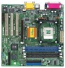
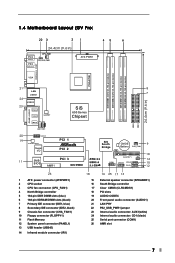
... IDE connector (IDE1, blue) 8 Secondary IDE connector (IDE2, black) 9 Chassis fan connector (CHA_FAN1) 10 Floppy connector (FLOPPY1) 11 Flash Memory 12 System panel connector (PANEL1) 13 USB header (USB45) 14 Infrared module connector (IR1) 18 15 16 17 18 19 20 21 22 23 24 25 26 16 25 17 13 External speaker connector (SPEAKER1) South Bridge controller Clear CMOS (CLRCMOS1) PCI slots AUDIO CODEC Front panel audio connector (AUDIO1) LAN PHY PS2_USB_PWR1 jumper Internal audio connector: AUX1(white) Internal audio connector: CD1 (black) Serial port connector (COM1...
... IDE connector (IDE1, blue) 8 Secondary IDE connector (IDE2, black) 9 Chassis fan connector (CHA_FAN1) 10 Floppy connector (FLOPPY1) 11 Flash Memory 12 System panel connector (PANEL1) 13 USB header (USB45) 14 Infrared module connector (IR1) 18 15 16 17 18 19 20 21 22 23 24 25 26 16 25 17 13 External speaker connector (SPEAKER1) South Bridge controller Clear CMOS (CLRCMOS1) PCI slots AUDIO CODEC Front panel audio connector (AUDIO1) LAN PHY PS2_USB_PWR1 jumper Internal audio connector: AUX1(white) Internal audio connector: CD1 (black) Serial port connector (COM1...
User Manual
Page 9
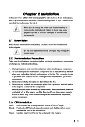
... power cord from the power supply. Whenever you install the motherboard, study the configuration of the socket lever. Failure to do so may cause severe damage to use a grounded wrist strap or touch a safety grounded object before you handle components. 3. Step 2. Carefully insert the CPU into it fits in the bag that the power is switched off or the power cord is a Micro ATX...
... power cord from the power supply. Whenever you install the motherboard, study the configuration of the socket lever. Failure to do so may cause severe damage to use a grounded wrist strap or touch a safety grounded object before you handle components. 3. Step 2. Carefully insert the CPU into it fits in the bag that the power is switched off or the power cord is a Micro ATX...
User Manual
Page 10
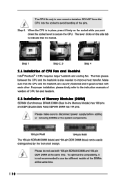
... the socket to the instruction manuals of vendors of CPU fan and heatsink. 2.5 Installation of the pins. For proper installation, please kindly refer to avoid bending of Memory Modules (DIMM) SDRAM (Synchronous DRAM) DIMM (Dual In-line Memory Module) has 168 pins and DDR (Double Data Rate) SDRAM DIMM has 184 pins. Please make sure to secure the CPU. Please do not use two different models of CPU Fan and Heatsink...
... the socket to the instruction manuals of vendors of CPU fan and heatsink. 2.5 Installation of the pins. For proper installation, please kindly refer to avoid bending of Memory Modules (DIMM) SDRAM (Synchronous DRAM) DIMM (Dual In-line Memory Module) has 168 pins and DDR (Double Data Rate) SDRAM DIMM has 184 pins. Please make sure to secure the CPU. Please do not use two different models of CPU Fan and Heatsink...

User Manual
Page 11
... chassis with v.92 Modem functionality. Installing an expansion card Step 1. Remove the system unit cover (if your motherboard is already installed in place and the DIMM is used to insert AMR cards with screws. Fasten the card to install a graphics card. Replace the system cover. 11 Unlock a DIMM slot by pressing the retaining clips outward. Align a DIMM on the slot such that have the 32-bit PCI...
... chassis with v.92 Modem functionality. Installing an expansion card Step 1. Remove the system unit cover (if your motherboard is already installed in place and the DIMM is used to insert AMR cards with screws. Fasten the card to install a graphics card. Replace the system cover. 11 Unlock a DIMM slot by pressing the retaining clips outward. Align a DIMM on the slot such that have the 32-bit PCI...
User Manual
Page 12
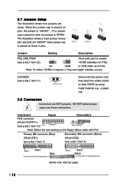
... motherboard Blue PIN1 IDE2 Black Connect to the IDE devices 80-Pin ATA 100/133 cable 12 If no jumper cap is placed on pins, the jumper is "SHORT". CLRCMOS (see p.6/p.7 item 22) 23 Short pin2, pin3 to clear CMOS by using metal material, e.g., a paper clip. 2.8 Connectors Connectors are NOT jumpers. Jumper Setting Description PS2_USB_PWR1 12 (see p.6/p.7 item 17) Solder points Disconnect the power cord, then short the solder points to enable...
... motherboard Blue PIN1 IDE2 Black Connect to the IDE devices 80-Pin ATA 100/133 cable 12 If no jumper cap is placed on pins, the jumper is "SHORT". CLRCMOS (see p.6/p.7 item 22) 23 Short pin2, pin3 to clear CMOS by using metal material, e.g., a paper clip. 2.8 Connectors Connectors are NOT jumpers. Jumper Setting Description PS2_USB_PWR1 12 (see p.6/p.7 item 17) Solder points Disconnect the power cord, then short the solder points to enable...
User Manual
Page 13
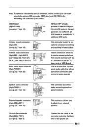
... front panel audio cable that allows convenient connection and control of audio devices. Connect the fan cable to the connector matching the black wire to the secondary IDE connector (IDE2, black). If the 4-USB ports on the rear panel are not sufficient, an USB header is an interface for 2 additional USB ports. External speaker connector (4-pin SPEAKER 1) (see p.6/p.7 item 15) Chassis fan connector (3-pin CHA_FAN1) (see p.6/p.7 item 13) ASRock I/OTM already provided 4 default USB ports. Note: To optimize compatibility and performance, please connect your hard disk drive to...
... front panel audio cable that allows convenient connection and control of audio devices. Connect the fan cable to the connector matching the black wire to the secondary IDE connector (IDE2, black). If the 4-USB ports on the rear panel are not sufficient, an USB header is an interface for 2 additional USB ports. External speaker connector (4-pin SPEAKER 1) (see p.6/p.7 item 15) Chassis fan connector (3-pin CHA_FAN1) (see p.6/p.7 item 13) ASRock I/OTM already provided 4 default USB ports. Note: To optimize compatibility and performance, please connect your hard disk drive to...
User Manual
Page 14
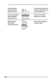
Connect an ATX power supply to the ground pin. This connector supports a serial port module. 14 CPU fan connector (3-pin CPU_FAN1) (see p.6/p.7 item 3) ATX power connector (20-pin ATXPWR1) (see p.6/p.7 item 1) COM1 connector (9-pin COM1) (see p.6/p.7 item 25) ATX Power Connector Connect the fan cable to the connector matching the black wire to the connector.
Connect an ATX power supply to the ground pin. This connector supports a serial port module. 14 CPU fan connector (3-pin CPU_FAN1) (see p.6/p.7 item 3) ATX power connector (20-pin ATXPWR1) (see p.6/p.7 item 1) COM1 connector (9-pin COM1) (see p.6/p.7 item 25) ATX Power Connector Connect the fan cable to the connector matching the black wire to the connector.
User Manual
Page 15
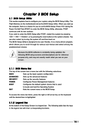
... key on the motherboard stores the BIOS Setup Utility. Because the BIOS software is constantly being updated, the following selections: MAIN Sets up the basic system configuration ADVANCED Sets up the advanced features SECURITY Sets up the computer, there is used to run the BIOS Setup. The Flash Memory on the keyboard until the desired item is highlighted. 3.1.2 Legend Bar At the bottom of the Setup Screen is designed to enter the BIOS Setup Utility...
... key on the motherboard stores the BIOS Setup Utility. Because the BIOS software is constantly being updated, the following selections: MAIN Sets up the basic system configuration ADVANCED Sets up the advanced features SECURITY Sets up the computer, there is used to run the BIOS Setup. The Flash Memory on the keyboard until the desired item is highlighted. 3.1.2 Legend Bar At the bottom of the Setup Screen is designed to enter the BIOS Setup Utility...
User Manual
Page 16
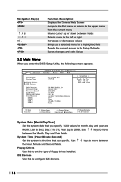
... Date System Time Floppy Drives IDE Devices BIOS Version Processor Type Processor Speed Cache Size Microcode Update Total Memory DDR1 DDR2 SDR1 SDR2 AMIBIOS SETUP UTILITY - Use keys to the time that you enter the BIOS Setup Utility, the following screen appears. System Time [Hour:Minute:Second] Set the system to move between the Hour, Minute and Second fields. Use keys to configure IDE devices. 16 IDE Devices Use this to 2099). Valid values for month, day, and year are Month...
... Date System Time Floppy Drives IDE Devices BIOS Version Processor Type Processor Speed Cache Size Microcode Update Total Memory DDR1 DDR2 SDR1 SDR2 AMIBIOS SETUP UTILITY - Use keys to the time that you enter the BIOS Setup Utility, the following screen appears. System Time [Hour:Minute:Second] Set the system to move between the Hour, Minute and Second fields. Use keys to configure IDE devices. 16 IDE Devices Use this to 2099). Valid values for month, day, and year are Month...
User Manual
Page 17
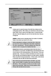
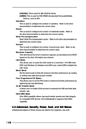
... to recognize the installed hard disk. [Auto]:Select [Auto] to automatically detect hard disk drive. Below are the configuration options. If auto-detection is too old or too new. TYPE It allows user to select the type of the Primary IDE hard disk drives to active. 17 After entering the hard disk information into BIOS, use a disk utility, such as FDISK, to manually enter the IDE hard disk drive parameters. Before attempting to configure a hard disk drive, make sure you configured. [USER]: It allows user to manually enter the number...
... to recognize the installed hard disk. [Auto]:Select [Auto] to automatically detect hard disk drive. Below are the configuration options. If auto-detection is too old or too new. TYPE It allows user to select the type of the Primary IDE hard disk drives to active. 17 After entering the hard disk information into BIOS, use a disk utility, such as FDISK, to manually enter the IDE hard disk drive parameters. Before attempting to configure a hard disk drive, make sure you configured. [USER]: It allows user to manually enter the number...
User Manual
Page 18
... the correct value. Fast Programmed I/O Modes This allows user to set the PIO mode to enhance hard disk performance by optimizing the hard disk timing. 32 Bit Transfer Mode It allows user to enable 32-bit access to [On] will enhance hard disk performance by the BIOS based on the drive information you entered. Heads This is used to suppress Ultra DMA capability. 3.3 Advanced, Security, Power, Boot, and Exit Menus Detailed descriptions...
... the correct value. Fast Programmed I/O Modes This allows user to set the PIO mode to enhance hard disk performance by optimizing the hard disk timing. 32 Bit Transfer Mode It allows user to enable 32-bit access to [On] will enhance hard disk performance by the BIOS based on the drive information you entered. Heads This is used to suppress Ultra DMA capability. 3.3 Advanced, Security, Power, Boot, and Exit Menus Detailed descriptions...
User Manual
Page 19
... you how to activate the devices. 4.2.3 Utilities Menu The Utilities Menu shows the applications software that enhance the motherboard features. 4.2.1 Running The Support CD To begin using the support CD, insert the CD into your CD-ROM drive. or you need to contact ASRock or want to ASRock's website: http://www.asrock.com; Refer to display the menus. 4.2.2 Drivers Menu The Drivers Menu shows the available devices drivers if the system detects...
... you how to activate the devices. 4.2.3 Utilities Menu The Utilities Menu shows the applications software that enhance the motherboard features. 4.2.1 Running The Support CD To begin using the support CD, insert the CD into your CD-ROM drive. or you need to contact ASRock or want to ASRock's website: http://www.asrock.com; Refer to display the menus. 4.2.2 Drivers Menu The Drivers Menu shows the available devices drivers if the system detects...
User Manual
Page 20
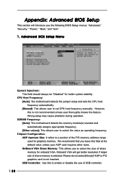
...," "Power," "Boot," and "Exit." 1. Wrong setup may cause problems during operation. SDRAM Frequency: [Auto]: The motherboard detects the memory module(s) inserted and automatically assigns appropriate frequency. [Other values]: This allows user to enable or disable the use of USB controller. 20 Chipset Configuration: AGP Aperture Size: It refers to a section of share memory for onboard VGA. We recommend that you to set CPU host frequency manually. Advanced BIOS Setup Menu Spread Spectrum: This field should always be "Disabled" for graphics memory...
...," "Power," "Boot," and "Exit." 1. Wrong setup may cause problems during operation. SDRAM Frequency: [Auto]: The motherboard detects the memory module(s) inserted and automatically assigns appropriate frequency. [Other values]: This allows user to enable or disable the use of USB controller. 20 Chipset Configuration: AGP Aperture Size: It refers to a section of share memory for onboard VGA. We recommend that you to set CPU host frequency manually. Advanced BIOS Setup Menu Spread Spectrum: This field should always be "Disabled" for graphics memory...
User Manual
Page 21
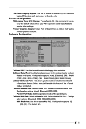
...Parallel Port Mode: Set the operation mode of the parallel port. The default is installed. USB Device Legacy Support: Use this to enable or disable support to emulate legacy I/O devices such as the primary graphics adapter. We recommend you to enable or disable the onboard infrared port feature. Configuration options: [Auto], [Disabled], [378], [278]. Configu ration options: [Disabled], [330], [300], [290], [292]. OnBoard Serial Port: Use this to enable or disable floppy drive controller. OnBoard Midi Port: Select address for the onboard serial ports or disable serial ports...
...Parallel Port Mode: Set the operation mode of the parallel port. The default is installed. USB Device Legacy Support: Use this to enable or disable support to emulate legacy I/O devices such as the primary graphics adapter. We recommend you to enable or disable the onboard infrared port feature. Configuration options: [Auto], [Disabled], [378], [278]. Configu ration options: [Disabled], [330], [300], [290], [292]. OnBoard Serial Port: Use this to enable or disable floppy drive controller. OnBoard Midi Port: Select address for the onboard serial ports or disable serial ports...
User Manual
Page 22
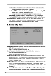
...]. OnBoard IDE: To enable either the primary IDE channel or the secondary IDE channel, set User Password. Password Check: Select the check point for Game Port or disable Game Port. User Password: This field shows the status of the hardware on your current password first in order to monitor the parameters for CPU temperature, Motherboard temperature, CPU fan speed, and critical voltage. 2. Valid password can check the status of the User Password. [Clear]: No password has been set. [Set]: User password has been set. Configuration options: [200h], [208h], [Disabled]. OnBoard...
...]. OnBoard IDE: To enable either the primary IDE channel or the secondary IDE channel, set User Password. Password Check: Select the check point for Game Port or disable Game Port. User Password: This field shows the status of the hardware on your current password first in order to monitor the parameters for CPU temperature, Motherboard temperature, CPU fan speed, and critical voltage. 2. Valid password can check the status of the User Password. [Clear]: No password has been set. [Set]: User password has been set. Configuration options: [200h], [208h], [Disabled]. OnBoard...
User Manual
Page 23
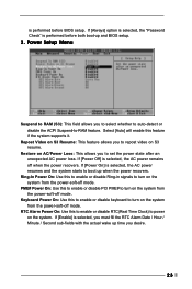
...-off mode. Select [Auto] will enable this to enable or disable PCI PME# to turn on the system. Keyboard Power On: Use this to enable or disable RTC(Real Time Clock) to RAM (S3): This field allows you desire. 23 PME# Power On: Use this feature if the system supports it. is selected, the AC power remains off mode. If [Power Off] is performed before both boot-up when the power recovers. Power Setup Menu...
...-off mode. Select [Auto] will enable this to enable or disable PCI PME# to turn on the system. Keyboard Power On: Use this to enable or disable RTC(Real Time Clock) to RAM (S3): This field allows you desire. 23 PME# Power On: Use this feature if the system supports it. is selected, the AC power remains off mode. If [Power Off] is performed before both boot-up when the power recovers. Power Setup Menu...
User Manual
Page 24
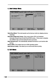
4. Boot to OS/2: This enables boot up . Exit Menu 24 Boot Device Priority: This allows you to OS/2 operating system. Boot Up Num-Lock: This automatically activates the Numeric Lock function after boot up to set the boot device priority. 5. If this screen is disabled, only ASRock logo is shown during Power-On-Self-Test (POST) routine. Boot-time Diagnostic Screen: This screen shows CPU and hardware information during the boot up routine by skipping memory retestings. Boot Setup Menu Quick Boot Mode: This mode speeds up the boot-up process.
4. Boot to OS/2: This enables boot up . Exit Menu 24 Boot Device Priority: This allows you to OS/2 operating system. Boot Up Num-Lock: This automatically activates the Numeric Lock function after boot up to set the boot device priority. 5. If this screen is disabled, only ASRock logo is shown during Power-On-Self-Test (POST) routine. Boot-time Diagnostic Screen: This screen shows CPU and hardware information during the boot up routine by skipping memory retestings. Boot Setup Menu Quick Boot Mode: This mode speeds up the boot-up process.


