User Manual
Page 1
Fatal1ty X79 Professional Series User Manual Version 1.0 Published November 2011 Copyright©2011 ASRock INC. All rights reserved. 1
Fatal1ty X79 Professional Series User Manual Version 1.0 Published November 2011 Copyright©2011 ASRock INC. All rights reserved. 1
User Manual
Page 4
... may apply, see www.dtsc.ca.gov/hazardouswaste/perchlorate" ASRock Website: http://www.asrock.com 4 Products and corporate names appearing in this manual. In no responsibility for any interference received, including interference that may appear in this manual may or may not be liable for any indirect, special..., interruption of business and the like), even if ASRock has been advised of the possibility of such damages arising from any kind, either expressed or implied, including but not limited to the contents of this manual, ASRock does not provide warranty of the FCC Rules. This...
... may apply, see www.dtsc.ca.gov/hazardouswaste/perchlorate" ASRock Website: http://www.asrock.com 4 Products and corporate names appearing in this manual. In no responsibility for any interference received, including interference that may appear in this manual may or may not be liable for any indirect, special..., interruption of business and the like), even if ASRock has been advised of the possibility of such damages arising from any kind, either expressed or implied, including but not limited to the contents of this manual, ASRock does not provide warranty of the FCC Rules. This...
User Manual
Page 7
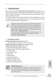
...-step guide to AHCI mode. www.asrock.com/support/index.asp 1.1 Package Contents Fatal1ty X79 Professional Series Motherboard (ATX Form Factor: 12.0-in x 9.6-in Storage Configuration to the hardware installation. It delivers excellent performance with robust design conforming to ASRock's commitment to BIOS setup and information of this manual occur, the updated version will...
...-step guide to AHCI mode. www.asrock.com/support/index.asp 1.1 Package Contents Fatal1ty X79 Professional Series Motherboard (ATX Form Factor: 12.0-in x 9.6-in Storage Configuration to the hardware installation. It delivers excellent performance with robust design conforming to ASRock's commitment to BIOS setup and information of this manual occur, the updated version will...
User Manual
Page 20
... are securely fastened and in good contact with 2011-Pin socket that the CPU and the heatsink are oriented on side closest to the instruction manuals of your CPU fan and heatsink. If you need to spray thermal interface material between the CPU and the heatsink to install the screws. Apply...
... are securely fastened and in good contact with 2011-Pin socket that the CPU and the heatsink are oriented on side closest to the instruction manuals of your CPU fan and heatsink. If you need to spray thermal interface material between the CPU and the heatsink to install the screws. Apply...
User Manual
Page 31
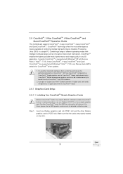
... Units (GPU) in CrossFireXTM mode. 2.8.1 Graphics Card Setup 2.8.1.1 Installing Two CrossFireXTM-Ready Graphics Cards Different CrossFireXTM cards may require different methods to AMD graphics card manuals for CrossFireXTM driver updates. 1. Insert one Radeon graphics card into PCIE1 slot and the other CrossFireXTM cards that the cards are supported with Service Pack...
... Units (GPU) in CrossFireXTM mode. 2.8.1 Graphics Card Setup 2.8.1.1 Installing Two CrossFireXTM-Ready Graphics Cards Different CrossFireXTM cards may require different methods to AMD graphics card manuals for CrossFireXTM driver updates. 1. Insert one Radeon graphics card into PCIE1 slot and the other CrossFireXTM cards that the cards are supported with Service Pack...
User Manual
Page 42
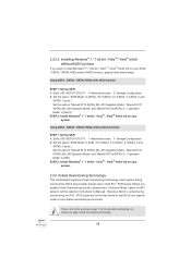
... convenient connection and control of audio devices. 1. For Windows® 7 / 7 64-bit / VistaTM / VistaTM 64-bit OS: Go to the "FrontMic" Tab in our manual and chassis manual to connect the remote controller receiver. Note the positive and negative pins before connecting the cables. PWRBTN (Power Switch): Connect to turn off your...
... convenient connection and control of audio devices. 1. For Windows® 7 / 7 64-bit / VistaTM / VistaTM 64-bit OS: Go to the "FrontMic" Tab in our manual and chassis manual to connect the remote controller receiver. Note the positive and negative pins before connecting the cables. PWRBTN (Power Switch): Connect to turn off your...
User Manual
Page 54
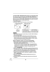
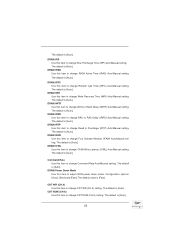
...Plug function, will cause the HDD damage and data loss. Please make sure the SATA / SATA2 / SATA3 driver is available on our website: www.asrock.com 2. A. 7-pin SATA data cable B. Below operation procedure is indicated in RAID / AHCI mode. The latest SATA / SATA2 / SATA3 driver ...is installed into system properly. Make sure your dealer or HDD user manual. 2.20 SATA / SATA2 / SATA3 HDD Hot Plug Feature and Operation Guide This motherboard supports Hot Plug feature for our motherboard, which supports SATA /...
...Plug function, will cause the HDD damage and data loss. Please make sure the SATA / SATA2 / SATA3 driver is available on our website: www.asrock.com 2. A. 7-pin SATA data cable B. Below operation procedure is indicated in RAID / AHCI mode. The latest SATA / SATA2 / SATA3 driver ...is installed into system properly. Make sure your dealer or HDD user manual. 2.20 SATA / SATA2 / SATA3 HDD Hot Plug Feature and Operation Guide This motherboard supports Hot Plug feature for our motherboard, which supports SATA /...
User Manual
Page 58
...] to fixed PCI / PCIE buses. A. A. Before you apply Untied Overclocking Technology. 58 Therefore, BCLK is untied during overclocking, BCLK enjoys better margin due to [Manual]. Using SATA / SATA2 / SATA3 HDDs with NCQ function STEP 1: Set Up UEFI. Enter UEFI SETUP UTILITY Advanced screen Storage Configuration. Enter UEFI SETUP...
...] to fixed PCI / PCIE buses. A. A. Before you apply Untied Overclocking Technology. 58 Therefore, BCLK is untied during overclocking, BCLK enjoys better margin due to [Manual]. Using SATA / SATA2 / SATA3 HDDs with NCQ function STEP 1: Set Up UEFI. Enter UEFI SETUP UTILITY Advanced screen Storage Configuration. Enter UEFI SETUP...

User Manual
Page 62
... cores to enable in each processor package. The default value is [All]. Active Processor Cores Use this item to change CAS# Latency (tCL) Auto/Manual setting. DRAM Timing Control DRAM tCL Use this to load XMP setting. Core Current Limit Use this item to add voltage when CPU is [Auto... mode. The default is in Turbo mode. DRAM Timing Control Load XMP Setting Use this item to change RAS# to CAS# Delay (tRCD) Auto/Manual setting. 62 Additional Turbo Voltage Use this item to add voltage when CPU is selected, the motherboard will detect the memory module(s) inserted and assign...
... cores to enable in each processor package. The default value is [All]. Active Processor Cores Use this item to change CAS# Latency (tCL) Auto/Manual setting. DRAM Timing Control DRAM tCL Use this to load XMP setting. Core Current Limit Use this item to add voltage when CPU is [Auto... mode. The default is in Turbo mode. DRAM Timing Control Load XMP Setting Use this item to change RAS# to CAS# Delay (tRCD) Auto/Manual setting. 62 Additional Turbo Voltage Use this item to add voltage when CPU is selected, the motherboard will detect the memory module(s) inserted and assign...
User Manual
Page 63
...ODT WR (CH A) setting. ODT WR (CH A) Use this item to change RAS to change Command Rate Auto/Manual setting. The default is [Auto]. DRAM tWR Use this item to RAS Delay (tRRD) Auto/Manual setting. DRAM tRRD Use this item to change Write to change Write Recovery Time (tWR) Auto...and [Fast]. ODT NOM (CH A) Use this item to change Read to change RAS# Active Time (tRAS) Auto/Manual setting. The default is [Auto]. DRAM tCWL Use this item to Precharge (tRTP) Auto/Manual setting. DRAM tFAW Use this item to adjust DDR power down mode. The default is [Auto]. DRAM tRAS...
...ODT WR (CH A) setting. ODT WR (CH A) Use this item to change RAS to change Command Rate Auto/Manual setting. The default is [Auto]. DRAM tWR Use this item to RAS Delay (tRRD) Auto/Manual setting. DRAM tRRD Use this item to change Write to change Write Recovery Time (tWR) Auto...and [Fast]. ODT NOM (CH A) Use this item to change Read to change RAS# Active Time (tRAS) Auto/Manual setting. The default is [Auto]. DRAM tCWL Use this item to Precharge (tRTP) Auto/Manual setting. DRAM tFAW Use this item to adjust DDR power down mode. The default is [Auto]. DRAM tRAS...
User Manual
Page 68
... Ratio Use this item to [Disabled] if above issues occur. Turbo Boost Power Limit Use this item to OS. Configuration options: [Auto] and [Manual]. In the C1 power state, the processor maintains the context of the system caches. Please note that enabling this to enable or disable CPU C3...
... Ratio Use this item to [Disabled] if above issues occur. Turbo Boost Power Limit Use this item to OS. Configuration options: [Auto] and [Manual]. In the C1 power state, the processor maintains the context of the system caches. Please note that enabling this to enable or disable CPU C3...
User Manual
Page 78
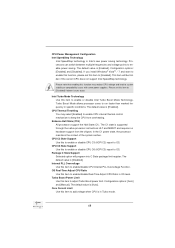
... allows you to set CPU fan 1 & 2's speed. Configuration options: [Full On] and [Automatic Mode]. Configuration options: [Full On], [Automatic Mode] and [Manual]. Chassis Fan 2 Setting This allows you to set chassis fan 2's speed. The default value is [Full On]. The default value is [Level 4]. Target Fan Speed...
... allows you to set CPU fan 1 & 2's speed. Configuration options: [Full On] and [Automatic Mode]. Configuration options: [Full On], [Automatic Mode] and [Manual]. Chassis Fan 2 Setting This allows you to set chassis fan 2's speed. The default value is [Full On]. The default value is [Level 4]. Target Fan Speed...
Quick Installation Guide
Page 7
... the user manual presented in , 30.5 cm x 22.4 cm) Fatal1ty X79 Professional Series Quick Installation Guide Fatal1ty X79 Professional Series Support CD 6 x Serial ATA (SATA) Data Cables (Optional) 2 x Serial ATA (SATA) HDD Power Cables (Optional) 1 x I/O Panel Shield 1 x Front USB 3.0 Panel 4 x HDD Screws 6 x Chassis Screws 1 x Rear USB 3.0 Bracket 2 x ASRock SLI_Bridge Cards 1 x ASRock SLI_Bridge_3S Card 1 x ASRock 3-Way SLI Bridge Card ASRock Reminds You...
... the user manual presented in , 30.5 cm x 22.4 cm) Fatal1ty X79 Professional Series Quick Installation Guide Fatal1ty X79 Professional Series Support CD 6 x Serial ATA (SATA) Data Cables (Optional) 2 x Serial ATA (SATA) HDD Power Cables (Optional) 1 x I/O Panel Shield 1 x Front USB 3.0 Panel 4 x HDD Screws 6 x Chassis Screws 1 x Rear USB 3.0 Bracket 2 x ASRock SLI_Bridge Cards 1 x ASRock SLI_Bridge_3S Card 1 x ASRock 3-Way SLI Bridge Card ASRock Reminds You...
Quick Installation Guide
Page 11
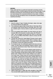
... 11 Fatal1ty X79 Professional Series Motherboard English Overclocking may be done at your friends. It should be less than 4GB for the reservation for possible damage caused by overclocking. Your friends can reduce the number of memory modules on page 18 for you can use . 4. WARNING Please realize that Windows® cannot use ASRock... Saver) mode, the voltage regulator can then load the OC profile in to their own system to adjust the mouse polling rate of the User Manual in the support CD. 2. This convenient BIOS update tool allows you to get the same OC settings.
... 11 Fatal1ty X79 Professional Series Motherboard English Overclocking may be done at your friends. It should be less than 4GB for the reservation for possible damage caused by overclocking. Your friends can reduce the number of memory modules on page 18 for you can use . 4. WARNING Please realize that Windows® cannot use ASRock... Saver) mode, the voltage regulator can then load the OC profile in to their own system to adjust the mouse polling rate of the User Manual in the support CD. 2. This convenient BIOS update tool allows you to get the same OC settings.
Quick Installation Guide
Page 17
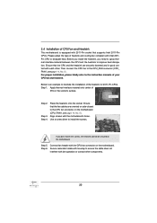
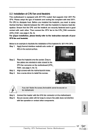
For proper installation, please kindly refer to the instruction manuals of IHS on the motherboard (CPU_ FAN1, see page 4, No. 5). Step 2. Place the heatsink onto the socket. Use a screw driver to improve heat dissipation. ...the screws, the heatsink cannot be secured on the motherboard. Then connect the CPU fan to the CPU_FAN connector (CPU_FAN1, see page 4, No. 5). English 17 Fatal1ty X79 Professional Series Motherboard Secure excess cable with tie-wrap to the CPU fan connector on the socket surface. Step 4. Ensure fan cables are securely fastened and...
For proper installation, please kindly refer to the instruction manuals of IHS on the motherboard (CPU_ FAN1, see page 4, No. 5). Step 2. Place the heatsink onto the socket. Use a screw driver to improve heat dissipation. ...the screws, the heatsink cannot be secured on the motherboard. Then connect the CPU fan to the CPU_FAN connector (CPU_FAN1, see page 4, No. 5). English 17 Fatal1ty X79 Professional Series Motherboard Secure excess cable with tie-wrap to the CPU fan connector on the socket surface. Step 4. Ensure fan cables are securely fastened and...
Quick Installation Guide
Page 28
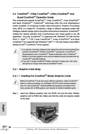
...Edition card with a 16-pipe card, both cards will operate as the example graphics card. English 28 Fatal1ty X79 Professional Series Motherboard Please check AMD's website for detailed installation guide. In below procedures, we use Radeon HD 5770...graphics card, a CrossFireXTM Ready motherboard and a CrossFireXTM Edition co-processor graphics card, must be installed correctly to AMD graphics card manuals for ATITM CrossFireXTM driver updates. 1. 2.6 CrossFireXTM, 3-Way CrossFireXTM, 4-Way CrossFireXTM and Quad CrossFireXTM Operation Guide This motherboard supports ...
...Edition card with a 16-pipe card, both cards will operate as the example graphics card. English 28 Fatal1ty X79 Professional Series Motherboard Please check AMD's website for detailed installation guide. In below procedures, we use Radeon HD 5770...graphics card, a CrossFireXTM Ready motherboard and a CrossFireXTM Edition co-processor graphics card, must be installed correctly to AMD graphics card manuals for ATITM CrossFireXTM driver updates. 1. 2.6 CrossFireXTM, 3-Way CrossFireXTM, 4-Way CrossFireXTM and Quad CrossFireXTM Operation Guide This motherboard supports ...

Quick Installation Guide
Page 39
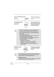
... OS: Go to the "FrontMic" Tab in our manual and chassis manual to function correctly. Connect Ground (GND) to MIC2_L. PWRBTN (Power Switch): Connect to the power switch on the chassis must support HDA to install your system using the power switch. 39 Fatal1ty X79 Professional Series Motherboard Consumer Infrared Module Header (4-pin CIR1) (see...
... OS: Go to the "FrontMic" Tab in our manual and chassis manual to function correctly. Connect Ground (GND) to MIC2_L. PWRBTN (Power Switch): Connect to the power switch on the chassis must support HDA to install your system using the power switch. 39 Fatal1ty X79 Professional Series Motherboard Consumer Infrared Module Header (4-pin CIR1) (see...
Quick Installation Guide
Page 50
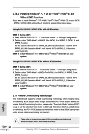
... SATA2_3, SATA3_0 and SATA3_1 ports.) Set the options "Marvell 9172 SATA3_M0_M1 Operation Mode", "Marvell 9172 SATA3_M2_M3 Operation Mode" and "Marvell 9172 eSATA3_0_1 Operation Mode" to [Manual]. Please refer to [IDE]. STEP 2: Install Windows® 7 / 7 64-bit / VistaTM / VistaTM 64-bit OS on your system. 2.17 Untied Overclocking Technology This motherboard supports... Mode" and "Marvell 9172 eSATA3_0_1 Operation Mode" to the warning on page 11 for the possible overclocking risk before you apply Untied Overclocking Technology. 50 Fatal1ty X79 Professional Series Motherboard English
... SATA2_3, SATA3_0 and SATA3_1 ports.) Set the options "Marvell 9172 SATA3_M0_M1 Operation Mode", "Marvell 9172 SATA3_M2_M3 Operation Mode" and "Marvell 9172 eSATA3_0_1 Operation Mode" to [Manual]. Please refer to [IDE]. STEP 2: Install Windows® 7 / 7 64-bit / VistaTM / VistaTM 64-bit OS on your system. 2.17 Untied Overclocking Technology This motherboard supports... Mode" and "Marvell 9172 eSATA3_0_1 Operation Mode" to the warning on page 11 for the possible overclocking risk before you apply Untied Overclocking Technology. 50 Fatal1ty X79 Professional Series Motherboard English
Quick Installation Guide
Page 51
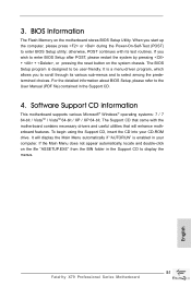
...program, which allows you start up the computer, please press or during the Power-On-Self-Test (POST) to display the menus. 51 Fatal1ty X79 Professional Series Motherboard English If the Main Menu does not appear automatically, locate and double-click on the motherboard stores BIOS Setup Utility. BIOS Information... "ASSETUP.EXE" from the BIN folder in the Support CD. 4. For the detailed information about BIOS Setup, please refer to the User Manual (PDF file) contained in the Support CD to enter BIOS Setup utility; It will enhance motherboard features. The Support CD that came with...
...program, which allows you start up the computer, please press or during the Power-On-Self-Test (POST) to display the menus. 51 Fatal1ty X79 Professional Series Motherboard English If the Main Menu does not appear automatically, locate and double-click on the motherboard stores BIOS Setup Utility. BIOS Information... "ASSETUP.EXE" from the BIN folder in the Support CD. 4. For the detailed information about BIOS Setup, please refer to the User Manual (PDF file) contained in the Support CD to enter BIOS Setup utility; It will enhance motherboard features. The Support CD that came with...
RAID Installation Guide
Page 2
1. Guide to Serial ATA (SATA) Hard Disks Installation of "User Manual" in this motherboard for internal storage devices. For SATA installation guide, please refer to SATA Hard Disks Installation 1.1 Serial ATA (SATA) Hard Disks Installation Intel X79 chipset supports Serial ATA (SATA) hard disks with RAID functions, including RAID 0, RAID 1, RAID 5, RAID 10...
1. Guide to Serial ATA (SATA) Hard Disks Installation of "User Manual" in this motherboard for internal storage devices. For SATA installation guide, please refer to SATA Hard Disks Installation 1.1 Serial ATA (SATA) Hard Disks Installation Intel X79 chipset supports Serial ATA (SATA) hard disks with RAID functions, including RAID 0, RAID 1, RAID 5, RAID 10...
