
User Manual
Page 9
...Professional Gaming i9 Series Quick Installation Guide • ASRock Fatal1ty X299 Professional Gaming i9 Series Support CD • 1 x I/O Panel Shield • 1 x ASRock SLI_HB_Bridge_2S Card (Optional) • 1 x ASRock 3-Way SLI-2S1S Bridge Card (Optional) • 4 x Serial ATA (SATA) Data Cables (Optional) • 2 x ASRock WiFi 2.4/5 GHz Antennas (Optional) • 3 x Screws for specific information about the model you for purchasing ASRock Fatal1ty X299 Professional Gaming i9 Series motherboard, a reliable motherboard produced under ASRock's consistently stringent quality control...
...Professional Gaming i9 Series Quick Installation Guide • ASRock Fatal1ty X299 Professional Gaming i9 Series Support CD • 1 x I/O Panel Shield • 1 x ASRock SLI_HB_Bridge_2S Card (Optional) • 1 x ASRock 3-Way SLI-2S1S Bridge Card (Optional) • 4 x Serial ATA (SATA) Data Cables (Optional) • 2 x ASRock WiFi 2.4/5 GHz Antennas (Optional) • 3 x Screws for specific information about the model you for purchasing ASRock Fatal1ty X299 Professional Gaming i9 Series motherboard, a reliable motherboard produced under ASRock's consistently stringent quality control...

User Manual
Page 11
Fatal1ty X299 Professional Gaming i9 Series Audio LAN • Supports AMD Quad CrossFireXTM, 3-Way CrossFireXTM and CrossFireXTM ** ** 3-Way CrossFireXTM is only supported with CPU with 44 lanes or 28 lanes. • Supports NVIDIA® Quad SLITM, 3-Way SLITM and SLITM*** *** This feature is only supported with CPU with 44 lanes or 28 lanes. • 1 x Vertical M.2 Socket (Key E) with the bundled WiFi- 802.11ac module (on the rear I/O) •...
Fatal1ty X299 Professional Gaming i9 Series Audio LAN • Supports AMD Quad CrossFireXTM, 3-Way CrossFireXTM and CrossFireXTM ** ** 3-Way CrossFireXTM is only supported with CPU with 44 lanes or 28 lanes. • Supports NVIDIA® Quad SLITM, 3-Way SLITM and SLITM*** *** This feature is only supported with CPU with 44 lanes or 28 lanes. • 1 x Vertical M.2 Socket (Key E) with the bundled WiFi- 802.11ac module (on the rear I/O) •...

User Manual
Page 13
... LED Strip • 1 x CPU Fan Connector (4-pin) * The CPU Fan Connector supports the CPU fan of maximum 1A (12W) fan power. • 1 x CPU Optional/Water Pump Fan Connector (4-pin) (Smart Fan Speed Control) * The CPU Optional/Water Pump Fan supports the water cooler fan of maximum 1.5A (18W) fan power. * CPU_OPT/W_PUMP, CHA_FAN1, CHA_FAN2 and CHA_ FAN3/W_PUMP can auto detect if 3-pin or 4-pin fan is occupied by a SATA-type M.2 device, SATA3_7 will be disabled. • 2 x SATA3 6.0 Gb/s Connectors by ASMedia ASM1061, sup- Fatal1ty X299 Professional Gaming i9 Series * If M2_3 is in use...
... LED Strip • 1 x CPU Fan Connector (4-pin) * The CPU Fan Connector supports the CPU fan of maximum 1A (12W) fan power. • 1 x CPU Optional/Water Pump Fan Connector (4-pin) (Smart Fan Speed Control) * The CPU Optional/Water Pump Fan supports the water cooler fan of maximum 1.5A (18W) fan power. * CPU_OPT/W_PUMP, CHA_FAN1, CHA_FAN2 and CHA_ FAN3/W_PUMP can auto detect if 3-pin or 4-pin fan is occupied by a SATA-type M.2 device, SATA3_7 will be disabled. • 2 x SATA3 6.0 Gb/s Connectors by ASMedia ASM1061, sup- Fatal1ty X299 Professional Gaming i9 Series * If M2_3 is in use...

User Manual
Page 17
... 2 x 288-pin DDR4 DIMM Slots (DDR4_C1, DDR4_D1) 7 CPU Fan Connector (CPU_FAN1) 8 RGB LED Header (RGB_LED2) 9 ATX Power Connector (ATXPWR1) 10 Virtual RAID On CPU Header (VROC1) 11 USB 3.0 Header (USB3_7_8) 12 Front Panel Type C USB 3.1 Header (USB31_TC_2) 13 USB 3.0 Header (USB3_5_6) 14 SATA3 Connectors (SATA3_0_1) 15 SATA3 Connectors (SATA3_2_3) 16 SATA3 Connectors (SATA3_4_5) 17 SATA3 Connectors (SATA3_6_7) 18 SATA3 Connectors (SATA3_A1_A2) 19 Power LED and Speaker Header (SPK_PLED1) 20 Chassis Fan Connector (CHA_FAN1) 21 System Panel Header (PANEL1) 22 Reset Switch (RSTBTN1) 23 Power Switch...
... 2 x 288-pin DDR4 DIMM Slots (DDR4_C1, DDR4_D1) 7 CPU Fan Connector (CPU_FAN1) 8 RGB LED Header (RGB_LED2) 9 ATX Power Connector (ATXPWR1) 10 Virtual RAID On CPU Header (VROC1) 11 USB 3.0 Header (USB3_7_8) 12 Front Panel Type C USB 3.1 Header (USB31_TC_2) 13 USB 3.0 Header (USB3_5_6) 14 SATA3 Connectors (SATA3_0_1) 15 SATA3 Connectors (SATA3_2_3) 16 SATA3 Connectors (SATA3_4_5) 17 SATA3 Connectors (SATA3_6_7) 18 SATA3 Connectors (SATA3_A1_A2) 19 Power LED and Speaker Header (SPK_PLED1) 20 Chassis Fan Connector (CHA_FAN1) 21 System Panel Header (PANEL1) 22 Reset Switch (RSTBTN1) 23 Power Switch...

User Manual
Page 38
..., reset the system, clear the CMOS values or flash the BIOS. Rename the file to quickly turn it on /off the system. This function is not installed; Then the LED starts to flash the BIOS. Press the BIOS Flashback Switch for three seconds. then install PSU and turn on . 5. English 30 USB BIOS Flashback port BIOS Flashback Switch (BIOS_FB1) (see p.8, No. 23) Power Power Switch allows users to "creative.rom" and plug your USB flash drive must be FAT32.3. Power Switch (PWRBTN...
..., reset the system, clear the CMOS values or flash the BIOS. Rename the file to quickly turn it on /off the system. This function is not installed; Then the LED starts to flash the BIOS. Press the BIOS Flashback Switch for three seconds. then install PSU and turn on . 5. English 30 USB BIOS Flashback port BIOS Flashback Switch (BIOS_FB1) (see p.8, No. 23) Power Power Switch allows users to "creative.rom" and plug your USB flash drive must be FAT32.3. Power Switch (PWRBTN...

User Manual
Page 39
... troubleshooting even easier. Please re-install the memory and CPU. Please re-install PCI-E devices or try using another VGA card. Please re-install IDE and SATA devices. If the problem still exists, please install only one memory module or try installing them in other devices. A0 - If the problem still exists, please remove all PCI-E devices or try removing all SATA devices. Please re-install the CPU and memory. Fatal1ty X299 Professional Gaming i9 Series 2.8 Dr. Debug Dr. Debug is installed correctly and then clear CMOS. 0d Problem...
... troubleshooting even easier. Please re-install the memory and CPU. Please re-install PCI-E devices or try using another VGA card. Please re-install IDE and SATA devices. If the problem still exists, please install only one memory module or try installing them in other devices. A0 - If the problem still exists, please remove all PCI-E devices or try removing all SATA devices. Please re-install the CPU and memory. Fatal1ty X299 Professional Gaming i9 Series 2.8 Dr. Debug Dr. Debug is installed correctly and then clear CMOS. 0d Problem...

User Manual
Page 43
... slot. Make sure the ASRock 3-Way SLI-2S1S Bridge Card is firmly in place. 3-Way SLI-2S1S Bridge Card 35 3-Way SLI2S1S English Please make sure that the cards are properly seated on the PCI Express graphics card are connected. Make sure that both power connectors on the slots. Fatal1ty X299 Professional Gaming i9 Series 2.9.2 Installing Three SLITM-Ready Graphics Cards Step 1 Insert one graphics card into PCIE1 slot, another graphics card to PCIE3 slot, and the other graphics card to the PCI Express graphics card...
... slot. Make sure the ASRock 3-Way SLI-2S1S Bridge Card is firmly in place. 3-Way SLI-2S1S Bridge Card 35 3-Way SLI2S1S English Please make sure that the cards are properly seated on the PCI Express graphics card are connected. Make sure that both power connectors on the slots. Fatal1ty X299 Professional Gaming i9 Series 2.9.2 Installing Three SLITM-Ready Graphics Cards Step 1 Insert one graphics card into PCIE1 slot, another graphics card to PCIE3 slot, and the other graphics card to the PCI Express graphics card...

User Manual
Page 46
... mode. 5. English CrossFire Bridge Step 2 Connect two graphics cards by installing a CrossFire Bridge on the CrossFire Bridge Interconnects on the slots. Please refer to three identical PCI Express x16 graphics cards. Make sure that are supported with Windows® 10 64-bit OS. * 3-Way CrossFireXTM is only supported with CPU with 44 lanes or 28 lanes. 1. Please refer to AMD graphics card manuals for detailed installation guide. 2.10.1 Installing Two CrossFireXTM-Ready Graphics Cards...
... mode. 5. English CrossFire Bridge Step 2 Connect two graphics cards by installing a CrossFire Bridge on the CrossFire Bridge Interconnects on the slots. Please refer to three identical PCI Express x16 graphics cards. Make sure that are supported with Windows® 10 64-bit OS. * 3-Way CrossFireXTM is only supported with CPU with 44 lanes or 28 lanes. 1. Please refer to AMD graphics card manuals for detailed installation guide. 2.10.1 Installing Two CrossFireXTM-Ready Graphics Cards...
User Manual
Page 49
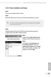
Then select Enable AMD CrossFireX and click Apply. English 41 AMD Catalyst Control Center Step 4 Double-click the AMD Catalyst Control Center icon in your graphics card and click Apply. Fatal1ty X299 Professional Gaming i9 Series 2.10.3 Driver Installation and Setup Step 1 Power on your computer. Step 3 Install the required drivers and CATALYST Control Center then restart your computer and boot into OS. Step 5 In the left pane, click Performance and then AMD CrossFireXTM...
Then select Enable AMD CrossFireX and click Apply. English 41 AMD Catalyst Control Center Step 4 Double-click the AMD Catalyst Control Center icon in your graphics card and click Apply. Fatal1ty X299 Professional Gaming i9 Series 2.10.3 Driver Installation and Setup Step 1 Power on your computer. Step 3 Install the required drivers and CATALYST Control Center then restart your computer and boot into OS. Step 5 In the left pane, click Performance and then AMD CrossFireXTM...

User Manual
Page 54
... CD-ROM drive. If the Main Menu does not appear automatically, locate and double click on the support CD driver page. Utilities Menu The Utilities Menu shows the application software that enhance the motherboard's features. Running The Support CD To begin using the support CD, insert the CD into your system will be auto-detected and listed on the file "ASRSETUP.EXE" in your computer. Therefore, the drivers you install can work...
... CD-ROM drive. If the Main Menu does not appear automatically, locate and double click on the support CD driver page. Utilities Menu The Utilities Menu shows the application software that enhance the motherboard's features. Running The Support CD To begin using the support CD, insert the CD into your system will be auto-detected and listed on the file "ASRSETUP.EXE" in your computer. Therefore, the drivers you install can work...

User Manual
Page 57
Click to select "Auto run at Windows Startup" if you start up to five different fan speeds using the graph. Settings Configure ASRock F-Stream. The fans will automatically shift to be launched when you want F-Stream to the next speed level when the assigned temperature is met. Fatal1ty X299 Professional Gaming i9 Series FAN-Tastic Tuning Configure up the Windows operating system. 49 English
Click to select "Auto run at Windows Startup" if you start up to five different fan speeds using the graph. Settings Configure ASRock F-Stream. The fans will automatically shift to be launched when you want F-Stream to the next speed level when the assigned temperature is met. Fatal1ty X299 Professional Gaming i9 Series FAN-Tastic Tuning Configure up the Windows operating system. 49 English

User Manual
Page 65
English 57 otherwise, the cable may cause damages to motherboard components. 1. Fatal1ty X299 Professional Gaming i9 Series 3.5 ASRock RGB LED ASRock RGB LED is a lighting control utility specifically designed for unique individuals with the package. 2. Simply by connecting the LED strip, you can customize various lighting schemes and patterns, including Static, Breathing, Strobe, Cycling, Music, Wave and more. Before installing or removing your RGB LED cable, please power off your RGB LED strips to build their...
English 57 otherwise, the cable may cause damages to motherboard components. 1. Fatal1ty X299 Professional Gaming i9 Series 3.5 ASRock RGB LED ASRock RGB LED is a lighting control utility specifically designed for unique individuals with the package. 2. Simply by connecting the LED strip, you can customize various lighting schemes and patterns, including Static, Breathing, Strobe, Cycling, Music, Wave and more. Before installing or removing your RGB LED cable, please power off your RGB LED strips to build their...

User Manual
Page 100
... Tools UEFI Tech Service Contact ASRock Tech Service if you are having trouble with your USB pen drive before using this function. 92 English After copying the drivers please change the SATA mode to your UEFI. Please setup network configuration before using Internet Flash. *For BIOS backup and recovery purpose, it is recommended to plug in RAID mode. Please setup network configuration before using UEFI Tech Service. Internet Flash - Easy RAID Installer Easy RAID Installer helps you to update your USB storage device. Instant Flash Save UEFI files in your USB storage device...
... Tools UEFI Tech Service Contact ASRock Tech Service if you are having trouble with your USB pen drive before using this function. 92 English After copying the drivers please change the SATA mode to your UEFI. Please setup network configuration before using Internet Flash. *For BIOS backup and recovery purpose, it is recommended to plug in RAID mode. Please setup network configuration before using UEFI Tech Service. Internet Flash - Easy RAID Installer Easy RAID Installer helps you to update your USB storage device. Instant Flash Save UEFI files in your USB storage device...

User Manual
Page 101
... activated. Internet Setting Enable or disable sound effects in the setup utility. Use "Secure Backup UEFI" to duplicate a working ROM image to the secondary flash ROM. Users may refer to the BIOS LEDs (BIOS_A_LED or BIOS_B_LED) to identify which enhances the safety and stability of the BIOS files to the active BIOS to ensure normal system operation. UEFI Download Server Select a server to update the backup BIOS manually. Fatal1ty X299 Professional Gaming i9 Series Secure Backup UEFI Whenever one of...
... activated. Internet Setting Enable or disable sound effects in the setup utility. Use "Secure Backup UEFI" to duplicate a working ROM image to the secondary flash ROM. Users may refer to the BIOS LEDs (BIOS_A_LED or BIOS_B_LED) to identify which enhances the safety and stability of the BIOS files to the active BIOS to ensure normal system operation. UEFI Download Server Select a server to update the backup BIOS manually. Fatal1ty X299 Professional Gaming i9 Series Secure Backup UEFI Whenever one of...

Quick Installation Guide
Page 6
... 2 x 288-pin DDR4 DIMM Slots (DDR4_C1, DDR4_D1) 7 CPU Fan Connector (CPU_FAN1) 8 RGB LED Header (RGB_LED2) 9 ATX Power Connector (ATXPWR1) 10 Virtual RAID On CPU Header (VROC1) 11 USB 3.0 Header (USB3_7_8) 12 Front Panel Type C USB 3.1 Header (USB31_TC_2) 13 USB 3.0 Header (USB3_5_6) 14 SATA3 Connectors (SATA3_0_1) 15 SATA3 Connectors (SATA3_2_3) 16 SATA3 Connectors (SATA3_4_5) 17 SATA3 Connectors (SATA3_6_7) 18 SATA3 Connectors (SATA3_A1_A2) 19 Power LED and Speaker Header (SPK_PLED1) 20 Chassis Fan Connector (CHA_FAN1) 21 System Panel Header (PANEL1) 22 Reset Switch (RSTBTN1) 23 Power Switch...
... 2 x 288-pin DDR4 DIMM Slots (DDR4_C1, DDR4_D1) 7 CPU Fan Connector (CPU_FAN1) 8 RGB LED Header (RGB_LED2) 9 ATX Power Connector (ATXPWR1) 10 Virtual RAID On CPU Header (VROC1) 11 USB 3.0 Header (USB3_7_8) 12 Front Panel Type C USB 3.1 Header (USB31_TC_2) 13 USB 3.0 Header (USB3_5_6) 14 SATA3 Connectors (SATA3_0_1) 15 SATA3 Connectors (SATA3_2_3) 16 SATA3 Connectors (SATA3_4_5) 17 SATA3 Connectors (SATA3_6_7) 18 SATA3 Connectors (SATA3_A1_A2) 19 Power LED and Speaker Header (SPK_PLED1) 20 Chassis Fan Connector (CHA_FAN1) 21 System Panel Header (PANEL1) 22 Reset Switch (RSTBTN1) 23 Power Switch...

Quick Installation Guide
Page 9
...Quick Installation Guide • ASRock Fatal1ty X299 Professional Gaming i9 Series Support CD • 1 x I/O Panel Shield • 1 x ASRock SLI_HB_Bridge_2S Card (Optional) • 1 x ASRock 3-Way SLI-2S1S Bridge Card (Optional) • 4 x Serial ATA (SATA) Data Cables (Optional) • 2 x ASRock WiFi 2.4/5 GHz Antennas (Optional) • 3 x Screws for specific information about the model you are using. It delivers excellent performance with robust design conforming to ASRock's commitment to change without further notice. You may find the latest VGA cards and CPU support list on...
...Quick Installation Guide • ASRock Fatal1ty X299 Professional Gaming i9 Series Support CD • 1 x I/O Panel Shield • 1 x ASRock SLI_HB_Bridge_2S Card (Optional) • 1 x ASRock 3-Way SLI-2S1S Bridge Card (Optional) • 4 x Serial ATA (SATA) Data Cables (Optional) • 2 x ASRock WiFi 2.4/5 GHz Antennas (Optional) • 3 x Screws for specific information about the model you are using. It delivers excellent performance with robust design conforming to ASRock's commitment to change without further notice. You may find the latest VGA cards and CPU support list on...

Quick Installation Guide
Page 13
...M2_3), support M Key type 2230/2242/2260/2280 M.2 SATA3 6.0 Gb/s module and M.2 PCI Express module up to Gen3 x4 (32 Gb/s)** ** Supports Intel® OptaneTM Technology ** Supports NVMe SSD as boot disks ** Supports ASRock U.2 Kit Connector • 1 x Virtual RAID On CPU Header • 1 x TPM Header • 1 x Power LED and Speaker Header • 2 x RGB LED Headers * Support up to 12V/3A, 36W LED Strip • 1 x CPU Fan Connector (4-pin) * The CPU Fan Connector supports the CPU fan of maximum 1A (12W) fan power. • 1 x CPU Optional/Water Pump Fan Connector (4-pin) (Smart Fan Speed...
...M2_3), support M Key type 2230/2242/2260/2280 M.2 SATA3 6.0 Gb/s module and M.2 PCI Express module up to Gen3 x4 (32 Gb/s)** ** Supports Intel® OptaneTM Technology ** Supports NVMe SSD as boot disks ** Supports ASRock U.2 Kit Connector • 1 x Virtual RAID On CPU Header • 1 x TPM Header • 1 x Power LED and Speaker Header • 2 x RGB LED Headers * Support up to 12V/3A, 36W LED Strip • 1 x CPU Fan Connector (4-pin) * The CPU Fan Connector supports the CPU fan of maximum 1A (12W) fan power. • 1 x CPU Optional/Water Pump Fan Connector (4-pin) (Smart Fan Speed...

Quick Installation Guide
Page 34
... LED starts to "creative.rom" and plug your USB flash drive must be FAT32. 3. 2.7 Smart Switches The motherboard has four smart switches: Power Switch, Reset Switch, Clear CMOS Switch and one BIOS Flashback Switch, allowing users to quickly turn on/off the system. Reset Switch (RSTBTN) (see p.3, No. 16) BIOS Flashback Switch allows users to the USB BIOS Flashback port. 4. Download the latest BIOS file from ASRock's website : http://www.asrock.com. 2. Copy the BIOS file to your USB flash drive.Please make sure the file system of your USB drive to flash the BIOS. Power Switch...
... LED starts to "creative.rom" and plug your USB flash drive must be FAT32. 3. 2.7 Smart Switches The motherboard has four smart switches: Power Switch, Reset Switch, Clear CMOS Switch and one BIOS Flashback Switch, allowing users to quickly turn on/off the system. Reset Switch (RSTBTN) (see p.3, No. 16) BIOS Flashback Switch allows users to the USB BIOS Flashback port. 4. Download the latest BIOS file from ASRock's website : http://www.asrock.com. 2. Copy the BIOS file to your USB flash drive.Please make sure the file system of your USB drive to flash the BIOS. Power Switch...

Quick Installation Guide
Page 35
... re-install the memory and CPU. Please re-install IDE and SATA devices. Please re-install the CPU and memory then clear CMOS. b0 Problem related to PCI-E devices. Fatal1ty X299 Professional Gaming i9 Series 2.8 Dr. Debug Dr. Debug is installed correctly and then clear CMOS. 0d Problem related to memory, VGA card or other devices. Code Description 00 Please check if the CPU is used to IDE or SATA devices. Please press reset or clear CMOS. 92 - 99 Problem related to memory. A7 Problem related to provide code information, which makes troubleshooting...
... re-install the memory and CPU. Please re-install IDE and SATA devices. Please re-install the CPU and memory then clear CMOS. b0 Problem related to PCI-E devices. Fatal1ty X299 Professional Gaming i9 Series 2.8 Dr. Debug Dr. Debug is installed correctly and then clear CMOS. 0d Problem related to memory, VGA card or other devices. Code Description 00 Please check if the CPU is used to IDE or SATA devices. Please press reset or clear CMOS. 92 - 99 Problem related to memory. A7 Problem related to provide code information, which makes troubleshooting...

Quick Installation Guide
Page 148
한 국 어 1 개요 ASRock Fatal1ty X299 Professional Gaming i9 Series ASRock ASRock BIOS ASRock ASRock VGA 카드와 CPU ASRock http://www.asrock.com. 1.1 • ASRock Fatal1ty X299 Professional Gaming i9 Series ATX ASRock Fatal1ty X299 Professional Gaming i9 Series ASRock Fatal1ty X299 Professional Gaming i9 Series 지원 CD • I/O 1 개 • ASRock SLI_HB_Bridge_2S 카드 1 ASRock 3-Way SLI-2S1S Bridge 카드 1 ATA (SATA 4 ASRock WiFi 2.4/5 GHz 안테나 2 M.2 3 144
한 국 어 1 개요 ASRock Fatal1ty X299 Professional Gaming i9 Series ASRock ASRock BIOS ASRock ASRock VGA 카드와 CPU ASRock http://www.asrock.com. 1.1 • ASRock Fatal1ty X299 Professional Gaming i9 Series ATX ASRock Fatal1ty X299 Professional Gaming i9 Series ASRock Fatal1ty X299 Professional Gaming i9 Series 지원 CD • I/O 1 개 • ASRock SLI_HB_Bridge_2S 카드 1 ASRock 3-Way SLI-2S1S Bridge 카드 1 ATA (SATA 4 ASRock WiFi 2.4/5 GHz 안테나 2 M.2 3 144


