User Manual
Page 6
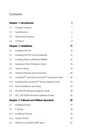
...1.2 Specifications 2 1.3 Motherboard Layout 7 1.4 I/O Panel 9 Chapter 2 Installation 11 2.1 Installing the CPU 12 2.2 Installing the CPU Fan and Heatsink 15 2.3 Installing Memory Modules (DIMM) 16 2.4 Expansion Slots (PCI Express Slots) 18 2.5 Jumpers Setup 19 2.6 Onboard Headers and Connectors 20 2.7 CrossFireXTM and Quad CrossFireXTM Operation Guide 25 2.7.1 Installing Two CrossFireXTM-Ready Graphics Cards 25 2.7.2 Driver Installation and Setup 27 2.8 M.2 WiFi/BT Module Installation Guide 28 2.9 M.2_SSD (NGFF) Module Installation Guide 30 Chapter 3 Software and...
...1.2 Specifications 2 1.3 Motherboard Layout 7 1.4 I/O Panel 9 Chapter 2 Installation 11 2.1 Installing the CPU 12 2.2 Installing the CPU Fan and Heatsink 15 2.3 Installing Memory Modules (DIMM) 16 2.4 Expansion Slots (PCI Express Slots) 18 2.5 Jumpers Setup 19 2.6 Onboard Headers and Connectors 20 2.7 CrossFireXTM and Quad CrossFireXTM Operation Guide 25 2.7.1 Installing Two CrossFireXTM-Ready Graphics Cards 25 2.7.2 Driver Installation and Setup 27 2.8 M.2 WiFi/BT Module Installation Guide 28 2.9 M.2_SSD (NGFF) Module Installation Guide 30 Chapter 3 Software and...
User Manual
Page 7
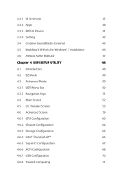
... BIOS & Drivers 41 3.3.4 Setting 42 3.4 Creative SoundBlaster Cinema3 43 3.5 Enabling USB Ports for Windows® 7 Installation 44 3.6 ASRock AURA RGB LED 47 Chapter 4 UEFI SETUP UTILITY 48 4.1 Introduction 48 4.2 EZ Mode 49 4.3 Advanced Mode 50 4.3.1 UEFI Menu Bar 50 4.3.2 Navigation Keys 51 4.4 Main Screen 52 4.5 OC Tweaker Screen 53 4.6 Advanced Screen 59 4.6.1 CPU Configuration 60 4.6.2 Chipset Configuration 62 4.6.3 Storage Configuration 65 4.6.4 Intel® Thunderbolt™ 66 4.6.5 Super IO Configuration 67 4.6.6 ACPI Configuration 68 4.6.7 USB...
... BIOS & Drivers 41 3.3.4 Setting 42 3.4 Creative SoundBlaster Cinema3 43 3.5 Enabling USB Ports for Windows® 7 Installation 44 3.6 ASRock AURA RGB LED 47 Chapter 4 UEFI SETUP UTILITY 48 4.1 Introduction 48 4.2 EZ Mode 49 4.3 Advanced Mode 50 4.3.1 UEFI Menu Bar 50 4.3.2 Navigation Keys 51 4.4 Main Screen 52 4.5 OC Tweaker Screen 53 4.6 Advanced Screen 59 4.6.1 CPU Configuration 60 4.6.2 Chipset Configuration 62 4.6.3 Storage Configuration 65 4.6.4 Intel® Thunderbolt™ 66 4.6.5 Super IO Configuration 67 4.6.6 ACPI Configuration 68 4.6.7 USB...

User Manual
Page 9
... performance with robust design conforming to ASRock's commitment to change without further notice. Because the motherboard specifications and the BIOS software might be updated, the content of this documentation, Chapter 1 and 2 contains the introduction of this motherboard, please visit our website for M.2 Socket (Optional) 1 English You may find the latest VGA cards and CPU support list on ASRock's website without notice. Chapter 3 contains the operation guide of the BIOS setup. Fatal1ty H270 Performance Series...
... performance with robust design conforming to ASRock's commitment to change without further notice. Because the motherboard specifications and the BIOS software might be updated, the content of this documentation, Chapter 1 and 2 contains the introduction of this motherboard, please visit our website for M.2 Socket (Optional) 1 English You may find the latest VGA cards and CPU support list on ASRock's website without notice. Chapter 3 contains the operation guide of the BIOS setup. Fatal1ty H270 Performance Series...

User Manual
Page 11
... memory 1024MB * The size of maximum shared memory may vary from different operating systems. • Three graphics output options: D-Sub, DVI-D and HDMI • Supports Triple Monitor • Supports HDMI with Differential Amplifier • TI® NE5532 Premium Headset Amplifier for Front Panel Audio Connector (Supports up to 1920x1200 @ 60Hz • Supports D-Sub with max. resolution up to 600 Ohm headsets) • Pure Power-In • Direct Drive Technology...
... memory 1024MB * The size of maximum shared memory may vary from different operating systems. • Three graphics output options: D-Sub, DVI-D and HDMI • Supports Triple Monitor • Supports HDMI with Differential Amplifier • TI® NE5532 Premium Headset Amplifier for Front Panel Audio Connector (Supports up to 1920x1200 @ 60Hz • Supports D-Sub with max. resolution up to 600 Ohm headsets) • Pure Power-In • Direct Drive Technology...
User Manual
Page 12
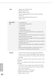
... 3 x USB 3.0 Type-A Ports (Supports ESD Protection (ASRock Full Spike Protection)) • 1 x USB 3.0 Type-C Port (Supports ESD Protection (ASRock Full Spike Protection)) • 1 x RJ-45 LAN Port with LED (ACT/LINK LED and SPEED LED) • HD Audio Jacks: Rear Speaker / Central / Bass / Line in / Front Speaker / Microphone (Gold Audio Jacks) Storage • 6 x SATA3 6.0 Gb/s Connectors, support RAID (RAID 0, RAID 1, RAID 5, RAID 10, Intel Rapid Storage Technology 15 and Intel Smart Response Technology), NCQ, AHCI and Hot Plug* * If M2_1 is occupied by a SATA-type M.2 device, SATA_5...
... 3 x USB 3.0 Type-A Ports (Supports ESD Protection (ASRock Full Spike Protection)) • 1 x USB 3.0 Type-C Port (Supports ESD Protection (ASRock Full Spike Protection)) • 1 x RJ-45 LAN Port with LED (ACT/LINK LED and SPEED LED) • HD Audio Jacks: Rear Speaker / Central / Bass / Line in / Front Speaker / Microphone (Gold Audio Jacks) Storage • 6 x SATA3 6.0 Gb/s Connectors, support RAID (RAID 0, RAID 1, RAID 5, RAID 10, Intel Rapid Storage Technology 15 and Intel Smart Response Technology), NCQ, AHCI and Hot Plug* * If M2_1 is occupied by a SATA-type M.2 device, SATA_5...

User Manual
Page 13
...18W) fan power. * CHA_FAN2 can auto detect if 3-pin or 4-pin fan is supported. • 3 x USB 2.0 Headers (Support 5 USB 2.0 ports) (Supports ESD Protection (ASRock Full Spike Protection)) • 2 x USB 3.0 Headers (Support 4 USB 3.0 ports) (Supports ESD Protection (ASRock Full Spike Protection)) BIOS Feature • AMI UEFI Legal BIOS with multilingual GUI support • ACPI 6.0 Compliant wake up events • SMBIOS 2.7 Support • CPU, GT_CPU, DRAM, VPPM, PCH 1.0V, VCCIO, VCCST, VCCSA, VCCPLL Voltage Multi-adjustment Hardware Monitor • Temperature Sensing: CPU, Chassis...
...18W) fan power. * CHA_FAN2 can auto detect if 3-pin or 4-pin fan is supported. • 3 x USB 2.0 Headers (Support 5 USB 2.0 ports) (Supports ESD Protection (ASRock Full Spike Protection)) • 2 x USB 3.0 Headers (Support 4 USB 3.0 ports) (Supports ESD Protection (ASRock Full Spike Protection)) BIOS Feature • AMI UEFI Legal BIOS with multilingual GUI support • ACPI 6.0 Compliant wake up events • SMBIOS 2.7 Support • CPU, GT_CPU, DRAM, VPPM, PCH 1.0V, VCCIO, VCCST, VCCSA, VCCPLL Voltage Multi-adjustment Hardware Monitor • Temperature Sensing: CPU, Chassis...
User Manual
Page 15
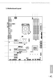
...-pin module) DDR4_B2 (64 bit, 288-pin module) 5 HDMI1 USB 3.0 T: USB3_TA_1 Top: B: USB3_TC_1 RJ-45 Center: REAR SPK Top: USB 3.0 T: USB1 B: USB2 CHA_FAN2 USB3_5_6 6 1 7 USB3_3_4 Central/Bass LINE IN Bottom: Optical SPDIF Top: Center: FRONT Bottom: MIC IN 26 LAN PCIE1 CT4 PCI Express 3.0 CT3 CT2 CT1 PCIE2 CLRMOS1 1 M2_2 RoHS 25 1 FATAL TY CMOS Battery AUDIO CODEC PCIE3 H270 Performance Intel H270 PCIE4 Ultra M.2 PCIe...
...-pin module) DDR4_B2 (64 bit, 288-pin module) 5 HDMI1 USB 3.0 T: USB3_TA_1 Top: B: USB3_TC_1 RJ-45 Center: REAR SPK Top: USB 3.0 T: USB1 B: USB2 CHA_FAN2 USB3_5_6 6 1 7 USB3_3_4 Central/Bass LINE IN Bottom: Optical SPDIF Top: Center: FRONT Bottom: MIC IN 26 LAN PCIE1 CT4 PCI Express 3.0 CT3 CT2 CT1 PCIE2 CLRMOS1 1 M2_2 RoHS 25 1 FATAL TY CMOS Battery AUDIO CODEC PCIE3 H270 Performance Intel H270 PCIE4 Ultra M.2 PCIe...

User Manual
Page 16
...) 10 SATA3 Connectors (SATA_0_1) 11 System Panel Header (PANEL1) 12 Power LED and Speaker Header (SPK_PLED1) 13 Chassis Fan / Waterpump Fan Connector (CHA_FAN3/W_PUMP) 14 Chassis Fan Connector (CHA_FAN1) 15 USB 2.0 Header (USB_3_4) 16 USB 2.0 Header (USB_5_6) 17 USB 2.0 Header (USB_7) 18 AURA RGB LED Header (RGB_LED) 19 COM Port Header (COM1) 20 TPM Header (TPMS1) 21 Chassis Intrusion Header (CI1) 22 Front Panel Audio Header (HD_AUDIO1) 23 Thunderbolt AIC Connector (TB1) 24 Thunderbolt AIC Connector (TB2) 25 Clear CMOS Jumper (CLRMOS1) 26 Chassis Fan Connector (CHA_FAN2) 8 English...
...) 10 SATA3 Connectors (SATA_0_1) 11 System Panel Header (PANEL1) 12 Power LED and Speaker Header (SPK_PLED1) 13 Chassis Fan / Waterpump Fan Connector (CHA_FAN3/W_PUMP) 14 Chassis Fan Connector (CHA_FAN1) 15 USB 2.0 Header (USB_3_4) 16 USB 2.0 Header (USB_5_6) 17 USB 2.0 Header (USB_7) 18 AURA RGB LED Header (RGB_LED) 19 COM Port Header (COM1) 20 TPM Header (TPMS1) 21 Chassis Intrusion Header (CI1) 22 Front Panel Audio Header (HD_AUDIO1) 23 Thunderbolt AIC Connector (TB1) 24 Thunderbolt AIC Connector (TB2) 25 Clear CMOS Jumper (CLRMOS1) 26 Chassis Fan Connector (CHA_FAN2) 8 English...
User Manual
Page 26
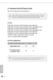
... PCIe Slot Configurations Single Graphics Card PCIE2 x16 PCIE4 N/A Two Graphics Cards in CrossFireXTM Mode x16 x4 For a better thermal environment, please connect a chassis fan to the motherboard's chassis fan connector (CHA_FAN1 or CHA_FAN2) when using multiple graphics cards. Before installing an expansion card, please make necessary hardware settings for the card before you start the installation. PCIE4 (PCIe 3.0 x16 slot) is used for PCI Express x1 lane width cards. PCIE5 (PCIe 3.0 x1 slot) is used for PCI Express x4 lane width graphics cards. PCIE3 (PCIe 3.0 x1 slot...
... PCIe Slot Configurations Single Graphics Card PCIE2 x16 PCIE4 N/A Two Graphics Cards in CrossFireXTM Mode x16 x4 For a better thermal environment, please connect a chassis fan to the motherboard's chassis fan connector (CHA_FAN1 or CHA_FAN2) when using multiple graphics cards. Before installing an expansion card, please make necessary hardware settings for the card before you start the installation. PCIE4 (PCIe 3.0 x16 slot) is used for PCI Express x1 lane width cards. PCIE5 (PCIe 3.0 x1 slot) is used for PCI Express x4 lane width graphics cards. PCIE3 (PCIe 3.0 x1 slot...

User Manual
Page 27
... the password, date, time, and user default profile will be detected. If you update the BIOS. To clear and reset the system parameters to short pin2 and pin3 on CLRMOS1 for 15 seconds, use a jumper cap to default setup, please turn off the computer and unplug the power cord from the power supply. The illustration shows a 3-pin jumper whose pin1 and pin2 are setup. After waiting for 5 seconds. Fatal1ty H270 Performance Series 2.5 Jumpers Setup The...
... the password, date, time, and user default profile will be detected. If you update the BIOS. To clear and reset the system parameters to short pin2 and pin3 on CLRMOS1 for 15 seconds, use a jumper cap to default setup, please turn off the computer and unplug the power cord from the power supply. The illustration shows a 3-pin jumper whose pin1 and pin2 are setup. After waiting for 5 seconds. Fatal1ty H270 Performance Series 2.5 Jumpers Setup The...
User Manual
Page 29
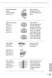
... the chassis speaker to 6.0 Gb/s data transfer rate. * If M2_1 is occupied by a SATA-type M.2 device, SATA_5 will be disabled. * If M2_2 is occupied by a SATA-type M.2 device, SATA_0 will be disabled. Each USB 3.0 header can support two ports. 21 English Fatal1ty H270 Performance Series Power LED and Speaker Header (7-pin SPK_PLED1) (see p.7, No. 12) Serial ATA3 Connectors (SATA_4_5: see p.7, No. 8) (SATA_2_3: see p.7, No. 9) (SATA_0_1: see p.7, No. 6) 1 GND P- SATA_5 SATA_3 These six SATA3 connectors support SATA data cables for internal storage devices...
... the chassis speaker to 6.0 Gb/s data transfer rate. * If M2_1 is occupied by a SATA-type M.2 device, SATA_5 will be disabled. * If M2_2 is occupied by a SATA-type M.2 device, SATA_0 will be disabled. Each USB 3.0 header can support two ports. 21 English Fatal1ty H270 Performance Series Power LED and Speaker Header (7-pin SPK_PLED1) (see p.7, No. 12) Serial ATA3 Connectors (SATA_4_5: see p.7, No. 8) (SATA_2_3: see p.7, No. 9) (SATA_0_1: see p.7, No. 6) 1 GND P- SATA_5 SATA_3 These six SATA3 connectors support SATA data cables for internal storage devices...
User Manual
Page 31
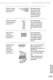
... a 24-pin ATX power connector. ATX Power Connector (24-pin ATXPWR1) (see p.7, No. 2) FAN_SPEED_CONTROL FAN_SPEED FAN_VOLTAGE GND 4 This motherboard pro- 3 2 vides a 4-Pin CPU fan 1 (Quiet Fan) connector. vides an 8-pin ATX 12V power connector. To use a 4 1 4-pin ATX power supply, please plug it along Pin 1 and Pin 5. ATX 12V Power Connector (8-pin ATX12V1) (see p.7, No. 24) DUMMY I2C_DATA I2C_CLOCK IRQ GND 1 GND SLP_S4# SLP_S3# PLUG_EVENT FRC_PWR Please connect a Thunderbolt™ add-in card (AIC) to the Thunderbolt AIC connector via the GPIO cable. *Please install the...
... a 24-pin ATX power connector. ATX Power Connector (24-pin ATXPWR1) (see p.7, No. 2) FAN_SPEED_CONTROL FAN_SPEED FAN_VOLTAGE GND 4 This motherboard pro- 3 2 vides a 4-Pin CPU fan 1 (Quiet Fan) connector. vides an 8-pin ATX 12V power connector. To use a 4 1 4-pin ATX power supply, please plug it along Pin 1 and Pin 5. ATX 12V Power Connector (8-pin ATX12V1) (see p.7, No. 24) DUMMY I2C_DATA I2C_CLOCK IRQ GND 1 GND SLP_S4# SLP_S3# PLUG_EVENT FRC_PWR Please connect a Thunderbolt™ add-in card (AIC) to the Thunderbolt AIC connector via the GPIO cable. *Please install the...

User Manual
Page 33
... top of the graphics cards. (The CrossFire Bridge is recommended to your graphics card vendor for detailed installation guide. 2.7.1 Installing Two CrossFireXTM-Ready Graphics Cards Step 1 Insert one graphics card into PCIE2 slot and the other graphics card to two identical PCI Express x16 graphics cards. 1. Download the drivers from the AMD's website: www.amd.com 3. Please refer to AMD graphics card manuals for details.) 25 English Fatal1ty H270 Performance Series 2.7 CrossFireXTM and Quad CrossFireXTM Operation Guide This motherboard supports CrossFireXTM and Quad...
... top of the graphics cards. (The CrossFire Bridge is recommended to your graphics card vendor for detailed installation guide. 2.7.1 Installing Two CrossFireXTM-Ready Graphics Cards Step 1 Insert one graphics card into PCIE2 slot and the other graphics card to two identical PCI Express x16 graphics cards. 1. Download the drivers from the AMD's website: www.amd.com 3. Please refer to AMD graphics card manuals for details.) 25 English Fatal1ty H270 Performance Series 2.7 CrossFireXTM and Quad CrossFireXTM Operation Guide This motherboard supports CrossFireXTM and Quad...
User Manual
Page 35
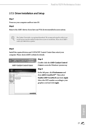
... Enable AMD CrossFireX and click Apply. We recommend using this utility to your computer and boot into OS. Please check AMD's website for details. English 27 Select the GPU number according to uninstall any VGA drivers installed in the Windows® system tray. Fatal1ty H270 Performance Series 2.7.2 Driver Installation and Setup Step 1 Power on your graphics card and click Apply. The Catalyst Uninstaller is an optional download. Step 3 Install the required drivers and CATALYST Control...
... Enable AMD CrossFireX and click Apply. We recommend using this utility to your computer and boot into OS. Please check AMD's website for details. English 27 Select the GPU number according to uninstall any VGA drivers installed in the Windows® system tray. Fatal1ty H270 Performance Series 2.7.2 Driver Installation and Setup Step 1 Power on your graphics card and click Apply. The Catalyst Uninstaller is an optional download. Step 3 Install the required drivers and CATALYST Control...

User Manual
Page 41
... listed on a specific item then follow the order from top to bottom to install those required drivers. If the Main Menu does not appear automatically, locate and double click on the file "ASRSETUP.EXE" in your CD-ROM drive. Therefore, the drivers you install can work properly. The CD automatically displays the Main Menu if "AUTORUN" is enabled in the Support CD to install it. Utilities Menu The Utilities Menu shows the application software...
... listed on a specific item then follow the order from top to bottom to install those required drivers. If the Main Menu does not appear automatically, locate and double click on the file "ASRSETUP.EXE" in your CD-ROM drive. Therefore, the drivers you install can work properly. The CD automatically displays the Main Menu if "AUTORUN" is enabled in the Support CD to install it. Utilities Menu The Utilities Menu shows the application software...

User Manual
Page 71
... ASPM Support This option enables/disables the control of ASPM on CPU side of memory that is installed. PCH DMI ASPM Support This option enables/disables the ASPM support for enhanced PCI Express power saving in OS. IGPU Multi-Monitor Select disable to one or more local APICs. PCIE6 Link Speed Select the link speed for PCIE4. Fatal1ty H270 Performance Series PCIE4 Link Speed Select the link speed for PCIE6. PCIE ASPM Support This option enables/disables the ASPM support for PCIE5...
... ASPM Support This option enables/disables the control of ASPM on CPU side of memory that is installed. PCH DMI ASPM Support This option enables/disables the ASPM support for enhanced PCI Express power saving in OS. IGPU Multi-Monitor Select disable to one or more local APICs. PCIE6 Link Speed Select the link speed for PCIE4. Fatal1ty H270 Performance Series PCIE4 Link Speed Select the link speed for PCIE6. PCIE ASPM Support This option enables/disables the ASPM support for PCIE5...
User Manual
Page 75
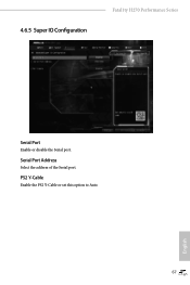
4.6.5 Super IO Configuration Fatal1ty H270 Performance Series Serial Port Enable or disable the Serial port. Serial Port Address Select the address of the Serial port. PS2 Y-Cable Enable the PS2 Y-Cable or set this option to Auto. 67 English
4.6.5 Super IO Configuration Fatal1ty H270 Performance Series Serial Port Enable or disable the Serial port. Serial Port Address Select the address of the Serial port. PS2 Y-Cable Enable the PS2 Y-Cable or set this option to Auto. 67 English

User Manual
Page 81
... (Auto IP), Auto ASRock Internet Flash downloads and updates the latest UEFI firmware version from our servers for you. Instant Flash Save UEFI files in your USB pen drive before using this tool. Fatal1ty H270 Performance Series Boot Manager Boot Manager is recommended to plug in your USB storage device and run Instant Flash to wait for the Boot Manager. Internet Flash - Boot Manager Enable/disable the Boot Manager. Please setup network configuration before using Internet Flash. *For BIOS backup and recovery purpose, it is specifically designed for the dual OS...
... (Auto IP), Auto ASRock Internet Flash downloads and updates the latest UEFI firmware version from our servers for you. Instant Flash Save UEFI files in your USB pen drive before using this tool. Fatal1ty H270 Performance Series Boot Manager Boot Manager is recommended to plug in your USB storage device and run Instant Flash to wait for the Boot Manager. Internet Flash - Boot Manager Enable/disable the Boot Manager. Please setup network configuration before using Internet Flash. *For BIOS backup and recovery purpose, it is specifically designed for the dual OS...
User Manual
Page 82
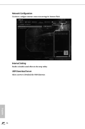
Network Configuration Use this to download the UEFI firmware. 74 English Internet Setting Enable or disable sound effects in the setup utility. UEFI Download Server Select a server to configure internet connection settings for Internet Flash.
Network Configuration Use this to download the UEFI firmware. 74 English Internet Setting Enable or disable sound effects in the setup utility. UEFI Download Server Select a server to configure internet connection settings for Internet Flash.

User Manual
Page 86
4.9 Security Screen In this option to enable or disable support for Windows 8.1 Secure Boot. You may set or change the supervisor/user password for the system. Intel(R) Platform Trust Technology Enable/disable Intel PTT in the UEFI Setup Utility. Secure Boot Use this item to use discrete TPM Module. 78 English Supervisor Password Set or change the settings in ME. Disable this section you may also clear the user password. Users are unable to remove the password. Only the administrator has authority...
4.9 Security Screen In this option to enable or disable support for Windows 8.1 Secure Boot. You may set or change the supervisor/user password for the system. Intel(R) Platform Trust Technology Enable/disable Intel PTT in the UEFI Setup Utility. Secure Boot Use this item to use discrete TPM Module. 78 English Supervisor Password Set or change the settings in ME. Disable this section you may also clear the user password. Users are unable to remove the password. Only the administrator has authority...


