User Manual
Page 8
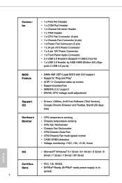
...-bit / 8 64-bit / 7 32-bit / 7 64-bit / XP 32-bit English Certifica- • FCC, CE, WHQL tions • ErP/EuP Ready (ErP/EuP ready power supply is re-
...-bit / 8 64-bit / 7 32-bit / 7 64-bit / XP 32-bit English Certifica- • FCC, CE, WHQL tions • ErP/EuP Ready (ErP/EuP ready power supply is re-
User Manual
Page 18
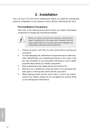
... the motherboard, peripherals, and/or components. 1. Hold components by the edges and do not over-tighten the screws! Unplug the power cord from the power supply. Failure to ensure that the power is switched off or the power cord is an Micro ATX form factor motherboard. To avoid damaging the motherboard...
... the motherboard, peripherals, and/or components. 1. Hold components by the edges and do not over-tighten the screws! Unplug the power cord from the power supply. Failure to ensure that the power is switched off or the power cord is an Micro ATX form factor motherboard. To avoid damaging the motherboard...

User Manual
Page 23
... expansion cards that the power supply is switched off or the power cord is used for the card before you start the installation. Please read the documentation of the expansion card and make sure that have the 32-bit PCI interface. PCI Slot: PCI slot is unplugged. FM2A88M-HD+ 2.4 Expansion Slots (PCI and...
... expansion cards that the power supply is switched off or the power cord is used for the card before you start the installation. Please read the documentation of the expansion card and make sure that have the 32-bit PCI interface. PCI Slot: PCI slot is unplugged. FM2A88M-HD+ 2.4 Expansion Slots (PCI and...
User Manual
Page 24
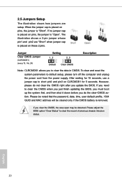
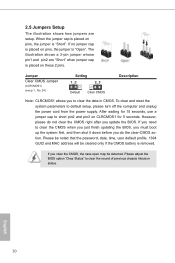
... parameters to clear the data in CMOS. If you to default setup, please turn off the computer and unplug the power cord from the power supply. However, please do the clear-CMOS ac- 2.5 Jumpers Setup The illustration shows how jumpers are "Short" when jumper cap is placed on CLRCMOS1 for 15...
... parameters to clear the data in CMOS. If you to default setup, please turn off the computer and unplug the power cord from the power supply. However, please do the clear-CMOS ac- 2.5 Jumpers Setup The illustration shows how jumpers are "Short" when jumper cap is placed on CLRCMOS1 for 15...
User Manual
Page 28
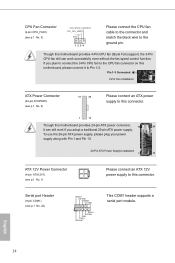
...24 Pin 1-3 Connected 3-Pin Fan Installation ATX Power Connector (24-pin ATXPWR1) (see p.10 No. 1) Please connect an ATX 12V power supply to this motherboard provides 24-pin ATX power connector, 12 24 it to this connector. 1 13 Though this connector. If you adopt a traditional... 20-pin ATX power supply. Serial port Header (9-pin COM1) (see p.10 No. 3) GND 1 2 3 4 Please connect the CPU fan cable to the connector and match...
...24 Pin 1-3 Connected 3-Pin Fan Installation ATX Power Connector (24-pin ATXPWR1) (see p.10 No. 1) Please connect an ATX 12V power supply to this motherboard provides 24-pin ATX power connector, 12 24 it to this connector. 1 13 Though this connector. If you adopt a traditional... 20-pin ATX power supply. Serial port Header (9-pin COM1) (see p.10 No. 3) GND 1 2 3 4 Please connect the CPU fan cable to the connector and match...
User Manual
Page 46
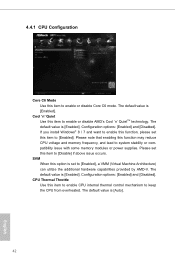
... Throttle Use this function may reduce CPU voltage and memory frequency, and lead to system stability or compatibility issue with some memory modules or power supplies. The default value is [Enabled]. The default value is [Auto]. 42 English 4.4.1 CPU Configuration Core C6 Mode Use this item to enable or disable AMD...
... Throttle Use this function may reduce CPU voltage and memory frequency, and lead to system stability or compatibility issue with some memory modules or power supplies. The default value is [Enabled]. The default value is [Auto]. 42 English 4.4.1 CPU Configuration Core C6 Mode Use this item to enable or disable AMD...

Quick Installation Guide
Page 9
...-bit / 8 64-bit / 7 32-bit / 7 64-bit / XP 32-bit English Certifica- • FCC, CE, WHQL tions • ErP/EuP Ready (ErP/EuP ready power supply is re- quired) 8
...-bit / 8 64-bit / 7 32-bit / 7 64-bit / XP 32-bit English Certifica- • FCC, CE, WHQL tions • ErP/EuP Ready (ErP/EuP ready power supply is re- quired) 8
Quick Installation Guide
Page 15
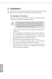
... note of your motherboard directly on a grounded antistatic pad or in the bag that comes with the component. 5. Unplug the power cord from the power supply. Before you install motherboard components or change any component, place it . 2. Installation This is detached from the wall socket before you install the motherboard, study...
... note of your motherboard directly on a grounded antistatic pad or in the bag that comes with the component. 5. Unplug the power cord from the power supply. Before you install motherboard components or change any component, place it . 2. Installation This is detached from the wall socket before you install the motherboard, study...
Quick Installation Guide
Page 20
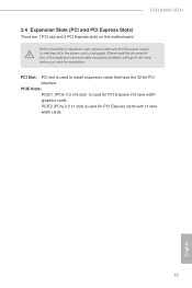
... 3.0 x16 slot) is used for PCI Express x16 lane width graphics cards PCIE2 (PCIe 2.0 x1 slot) is used to install expansion cards that the power supply is switched off or the power cord is used for the card before you start the installation. Before installing an expansion card, please make necessary... English Please read the documentation of the expansion card and make sure that have the 32-bit PCI interface. PCI Slot: PCI slot is unplugged. FM2A88M-HD+ 2.4 Expansion Slots (PCI and PCI Express Slots) There are 1 PCI slot and 2 PCI Express slots on this motherboard.
... 3.0 x16 slot) is used for PCI Express x16 lane width graphics cards PCIE2 (PCIe 2.0 x1 slot) is used to install expansion cards that the power supply is switched off or the power cord is used for the card before you start the installation. Before installing an expansion card, please make necessary... English Please read the documentation of the expansion card and make sure that have the 32-bit PCI interface. PCI Slot: PCI slot is unplugged. FM2A88M-HD+ 2.4 Expansion Slots (PCI and PCI Express Slots) There are 1 PCI slot and 2 PCI Express slots on this motherboard.
Quick Installation Guide
Page 21
... is removed. Please adjust the BIOS option "Clear Status" to default setup, please turn off the computer and unplug the power cord from the power supply. If you update the BIOS. If no jumper cap is placed on pins, the jumper is placed on CLRCMOS1 for 5 seconds. If you do not...
... is removed. Please adjust the BIOS option "Clear Status" to default setup, please turn off the computer and unplug the power cord from the power supply. If you update the BIOS. If no jumper cap is placed on pins, the jumper is placed on CLRCMOS1 for 5 seconds. If you do not...
Quick Installation Guide
Page 25
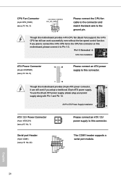
...match the black wire to the ground pin. CPU Fan Connector FAN_SPEED_CONTROL (4-pin CPU_FAN1) CPU_FAN_SPEED +12V (see p.1 No. 1) Please connect an ATX 12V power supply to this connector. Pin 1-3 Connected 3-Pin Fan Installation ATX Power Connector (24-pin ATXPWR1) (see p.1 No. 22) RRXD1 DDTR#1 DDSR#1 CCTS#1 ... without the fan speed control function. Serial port Header (9-pin COM1) (see p.1 No. 5) 12 24 Please connect an ATX power supply to this connector. 1 13 Though this motherboard provides 24-pin ATX power connector, 12 24 it can work if you plan to connect...
...match the black wire to the ground pin. CPU Fan Connector FAN_SPEED_CONTROL (4-pin CPU_FAN1) CPU_FAN_SPEED +12V (see p.1 No. 1) Please connect an ATX 12V power supply to this connector. Pin 1-3 Connected 3-Pin Fan Installation ATX Power Connector (24-pin ATXPWR1) (see p.1 No. 22) RRXD1 DDTR#1 DDSR#1 CCTS#1 ... without the fan speed control function. Serial port Header (9-pin COM1) (see p.1 No. 5) 12 24 Please connect an ATX power supply to this connector. 1 13 Though this motherboard provides 24-pin ATX power connector, 12 24 it can work if you plan to connect...

