User Manual
Page 3
...5 1.1 Package Contents 5 1.2 Specifications 6 1.3 Motherboard Layout 9 1.4 ASRock 8CH I/O 10 2 Installation 11 2.1 Screw Holes 11 2.2 Pre-installation Precautions 11 2.3 CPU Installation 12 2.4 Installation of CPU Fan and Heatsink 14 2.5 Installation of Memory Modules (DIMM 15 2.6 Expansion... 23 3.1 Introduction 23 3.1.1 BIOS Menu Bar 23 3.1.2 Navigation Keys 24 3.2 Main Screen 24 3.3 Advanced Screen 24 3.3.1 CPU Configuration 25 3.3.2 Chipset Configuration 27 3.3.3 ACPI Configuration 28 3.3.4 IDE Configuration 29 3.3.5 PCIPnP Configuration 31 3.3.6 Floppy Configuration 32 ...
...5 1.1 Package Contents 5 1.2 Specifications 6 1.3 Motherboard Layout 9 1.4 ASRock 8CH I/O 10 2 Installation 11 2.1 Screw Holes 11 2.2 Pre-installation Precautions 11 2.3 CPU Installation 12 2.4 Installation of CPU Fan and Heatsink 14 2.5 Installation of Memory Modules (DIMM 15 2.6 Expansion... 23 3.1 Introduction 23 3.1.1 BIOS Menu Bar 23 3.1.2 Navigation Keys 24 3.2 Main Screen 24 3.3 Advanced Screen 24 3.3.1 CPU Configuration 25 3.3.2 Chipset Configuration 27 3.3.3 ACPI Configuration 28 3.3.4 IDE Configuration 29 3.3.5 PCIPnP Configuration 31 3.3.6 Floppy Configuration 32 ...
User Manual
Page 4
4 Software Support 39 4.1 Install Operating System 39 4.2 Support CD Information 39 4.2.1 Running Support CD 39 4.2.2 Drivers Menu 39 4.2.3 Utilities Menu 39 4.2.4 "LGA 775 CPU Installation Live Demo" Program .. 39 4.2.5 Contact Information 39 4
4 Software Support 39 4.1 Install Operating System 39 4.2 Support CD Information 39 4.2.1 Running Support CD 39 4.2.2 Drivers Menu 39 4.2.3 Utilities Menu 39 4.2.4 "LGA 775 CPU Installation Live Demo" Program .. 39 4.2.5 Contact Information 39 4
User Manual
Page 5
... modifications of this manual, chapter 1 and 2 contain introduction of the Support CD. ASRock website http://www.asrock.com 1.1 Package Contents ASRock ConRoe865PE Motherboard (ATX Form Factor: 12.0-in x 9.0-in, 30.5 cm x 22.9 cm) ASRock ConRoe865PE Quick Installation Guide ASRock ConRoe865PE Support CD (including LGA 775 CPU Installation Live Demo) One 80-conductor Ultra ATA 66/100 IDE Ribbon Cable...
... modifications of this manual, chapter 1 and 2 contain introduction of the Support CD. ASRock website http://www.asrock.com 1.1 Package Contents ASRock ConRoe865PE Motherboard (ATX Form Factor: 12.0-in x 9.0-in, 30.5 cm x 22.9 cm) ASRock ConRoe865PE Quick Installation Guide ASRock ConRoe865PE Support CD (including LGA 775 CPU Installation Live Demo) One 80-conductor Ultra ATA 66/100 IDE Ribbon Cable...
User Manual
Page 6
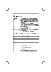
... (in , 30.5 cm x 22.9 cm - Audio Jack: Side Speaker/Rear Speaker/Central/Bass/ Line in/Front Speaker/Microphone (see CAUTION 8) - ASRock U-COP (see CAUTION 7) - Supports EM64T CPU - Realtek PCI LAN 8101L - 1.2 Specifications Platform CPU Chipset Memory Hybrid Booster Expansion Slot Audio LAN Rear Panel I /O - 1 x PS/2 Mouse Port - 1 x PS/2 Keyboard Port - 1 x Serial Port: COM1...
... (in , 30.5 cm x 22.9 cm - Audio Jack: Side Speaker/Rear Speaker/Central/Bass/ Line in/Front Speaker/Microphone (see CAUTION 8) - ASRock U-COP (see CAUTION 7) - Supports EM64T CPU - Realtek PCI LAN 8101L - 1.2 Specifications Platform CPU Chipset Memory Hybrid Booster Expansion Slot Audio LAN Rear Panel I /O - 1 x PS/2 Mouse Port - 1 x PS/2 Keyboard Port - 1 x Serial Port: COM1...
User Manual
Page 7
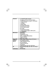
...7 CD in header - Supports "Plug and Play" - Supports jumperfree - Drivers, Utilities, AntiVirus Software (Trial Version) - CPU Fan Tachometer - Connector BIOS Feature Support CD Hardware Monitor OS Certifications - 2 x Serial ATA 1.5Gb/s connectors (No Support for... and "Hot Plug" functions) - 2 x ATA100 IDE connectors (support 4 x IDE devices) - 1 x Floppy connector - 1 x IR header - 1 x Game header - CPU Quiet Fan - ACPI 1.1 Compliance Wake Up Events - Voltage Monitoring: +12V, +5V, +3.3V, Vcore - Chassis Fan Tachometer - AMI Legal BIOS - AMBIOS 2.3.1 Support - Microsoft&#...
...7 CD in header - Supports "Plug and Play" - Supports jumperfree - Drivers, Utilities, AntiVirus Software (Trial Version) - CPU Fan Tachometer - Connector BIOS Feature Support CD Hardware Monitor OS Certifications - 2 x Serial ATA 1.5Gb/s connectors (No Support for... and "Hot Plug" functions) - 2 x ATA100 IDE connectors (support 4 x IDE devices) - 1 x Floppy connector - 1 x IR header - 1 x Game header - CPU Quiet Fan - ACPI 1.1 Compliance Wake Up Events - Voltage Monitoring: +12V, +5V, +3.3V, Vcore - Chassis Fan Tachometer - AMI Legal BIOS - AMBIOS 2.3.1 Support - Microsoft&#...
User Manual
Page 8
...to perform over-clocking. This motherboard supports Untied Overclocking Technology. This motherboard supports Dual Channel Memory Technology. Do NOT use a FSB1066-CPU on page 15 for USB 2.0 works fine under Microsoft® Windows® 98 / ME. 8 For microphone input, this ... CL2.5 memory module. 6. Power Management for proper installation. 5. Besides, if you want this motherboard! Frequencies other than the recommended CPU bus frequencies may cause permanent damage! 9. For audio output, this motherboard, it will automatically shutdown. FSB1066 is detected, the system...
...to perform over-clocking. This motherboard supports Untied Overclocking Technology. This motherboard supports Dual Channel Memory Technology. Do NOT use a FSB1066-CPU on page 15 for USB 2.0 works fine under Microsoft® Windows® 98 / ME. 8 For microphone input, this ... CL2.5 memory module. 6. Power Management for proper installation. 5. Besides, if you want this motherboard! Frequencies other than the recommended CPU bus frequencies may cause permanent damage! 9. For audio output, this motherboard, it will automatically shutdown. FSB1066 is detected, the system...
User Manual
Page 9
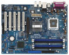
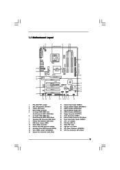
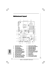
...Intel 865PE/865G Chipset Super IO 4Mb BIOS PCI LAN AUDIO CODEC JR1 JL1 1 AUDIO1 CD1 AGP 8X 1.5V_AGP1 PCI 1 1 FSB1 7.1CH PCI 2 ConRoe865PE PCI 3 PCI 4 PCI 5 GAME1 FLOPPY1 Intel ICH5 ` RoHS 1 USB45 CMOS Battery CLRCMOS0 SATA1 SATA2 USB2.0 1 USB67 SATA 1 IR1 1 SPEAKER1 PANEL... 16 15 CHA_FAN1 IDE1 IDE2 30.5cm (12.0 in) 7 8 9 10 11 12 13 14 1 PS2_USB_PWR1 Jumper 2 ATX 12V Connector (ATX12V1) 3 775-Pin CPU Socket 4 North Bridge Controller 5 2 x 184-pin DDR DIMM Slots (Dual Channel A: DDR1, DDR3; Black) 7 Secondary IDE Connector (IDE2, Black) 8 Primary IDE...
...Intel 865PE/865G Chipset Super IO 4Mb BIOS PCI LAN AUDIO CODEC JR1 JL1 1 AUDIO1 CD1 AGP 8X 1.5V_AGP1 PCI 1 1 FSB1 7.1CH PCI 2 ConRoe865PE PCI 3 PCI 4 PCI 5 GAME1 FLOPPY1 Intel ICH5 ` RoHS 1 USB45 CMOS Battery CLRCMOS0 SATA1 SATA2 USB2.0 1 USB67 SATA 1 IR1 1 SPEAKER1 PANEL... 16 15 CHA_FAN1 IDE1 IDE2 30.5cm (12.0 in) 7 8 9 10 11 12 13 14 1 PS2_USB_PWR1 Jumper 2 ATX 12V Connector (ATX12V1) 3 775-Pin CPU Socket 4 North Bridge Controller 5 2 x 184-pin DDR DIMM Slots (Dual Channel A: DDR1, DDR3; Black) 7 Secondary IDE Connector (IDE2, Black) 8 Primary IDE...
User Manual
Page 12
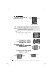
... two orientation key notches. Step 1-2. Step 2. Step 2-2. Pin1 orientation key notch orientation key notch Pin1 alignment key alignment key 775-LAND CPU 12 775-Pin Socket black line black line Do not force to fully open position at approximately 100 degrees. Step 1. Rotate the load plate... to insert the CPU into the socket, please check if the CPU surface is unclean or if there is found. 2.3 CPU Installation For the installation of Intel 775-LAND CPU, please follow the steps below. 775-Pin Socket Overview Before you...
... two orientation key notches. Step 1-2. Step 2. Step 2-2. Pin1 orientation key notch orientation key notch Pin1 alignment key alignment key 775-LAND CPU 12 775-Pin Socket black line black line Do not force to fully open position at approximately 100 degrees. Step 1. Rotate the load plate... to insert the CPU into the socket, please check if the CPU surface is unclean or if there is found. 2.3 CPU Installation For the installation of Intel 775-LAND CPU, please follow the steps below. 775-Pin Socket Overview Before you...
User Manual
Page 13
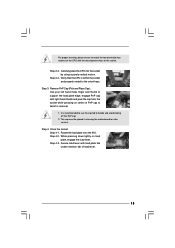
... the two alignment keys of load lever. 13 It is within the socket and properly mated to match the two orientation key notches of the CPU with right hand thumb and peel the cap from the socket while pressing on load plate, engage the load lever. Step 4-3. Carefully place the... CPU into the socket by using a purely vertical motion. Verify that the CPU is recommended to use the cap tab to assist in removal. 1. This cap must be placed if returning the motherboard...
... the two alignment keys of load lever. 13 It is within the socket and properly mated to match the two orientation key notches of the CPU with right hand thumb and peel the cap from the socket while pressing on load plate, engage the load lever. Step 4-3. Carefully place the... CPU into the socket by using a purely vertical motion. Verify that the CPU is recommended to use the cap tab to assist in removal. 1. This cap must be placed if returning the motherboard...
User Manual
Page 14
... installation, please kindly refer to the instruction manuals of heatsink and cooling fan compliant with 775-Pin socket that the CPU and the heatsink are oriented on fastener caps with fan operation or contact other . Connect fan header with remaining fasteners. 2.4 Installation ...the socket. Step 4. Ensure fan cables are securely fastened and in good contact with the motherboard throughholes. Then connect the CPU fan to the CPU fan connector on the motherboard. Rotate the fastener clockwise, then press down the fasteners without rotating them clockwise, the heatsink cannot...
... installation, please kindly refer to the instruction manuals of heatsink and cooling fan compliant with 775-Pin socket that the CPU and the heatsink are oriented on fastener caps with fan operation or contact other . Connect fan header with remaining fasteners. 2.4 Installation ...the socket. Step 4. Ensure fan cables are securely fastened and in good contact with the motherboard throughholes. Then connect the CPU fan to the CPU fan connector on the motherboard. Rotate the fastener clockwise, then press down the fasteners without rotating them clockwise, the heatsink cannot...
User Manual
Page 18
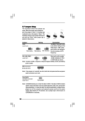
... Description "NORMAL" (short pin1, pin2) is the default setting for PS/2 +5V +5VSB or USB wake up events. After waiting for the over clocking of CPU frequency. 2.7 Jumpers Setup The illustration shows how jumpers are "Short" when jumper cap is placed on these 2 pins. When the jumper cap is placed on...
... Description "NORMAL" (short pin1, pin2) is the default setting for PS/2 +5V +5VSB or USB wake up events. After waiting for the over clocking of CPU frequency. 2.7 Jumpers Setup The illustration shows how jumpers are "Short" when jumper cap is placed on these 2 pins. When the jumper cap is placed on...
User Manual
Page 21
... functions. System Panel Header (9-pin PANEL1) (see p.9 No. 15) Chassis Speaker Header (4-pin SPEAKER 1) (see p.9 No. 16) Chassis Fan Connector (3-pin CHA_FAN1) (see p.9 No. 14) CPU Fan Connector (4-pin CPU_FAN1) (see p.9 No. 29) ATX Power Connector (20-pin ATXPWR1) (see p.9, No. 2) +5V JBB1 JBX MIDI_OUT JBY JBB2 MIDI_IN 1 +5V JAB2 JAY... the black wire to power up. 21 Failing to do so will cause the failure to the ground pin. GND +12V CPU_FAN_SPEED FAN_SPEED_CONTROL Please connect a CPU fan cable to this header.
... functions. System Panel Header (9-pin PANEL1) (see p.9 No. 15) Chassis Speaker Header (4-pin SPEAKER 1) (see p.9 No. 16) Chassis Fan Connector (3-pin CHA_FAN1) (see p.9 No. 14) CPU Fan Connector (4-pin CPU_FAN1) (see p.9 No. 29) ATX Power Connector (20-pin ATXPWR1) (see p.9, No. 2) +5V JBB1 JBX MIDI_OUT JBY JBB2 MIDI_IN 1 +5V JAB2 JAY... the black wire to power up. 21 Failing to do so will cause the failure to the ground pin. GND +12V CPU_FAN_SPEED FAN_SPEED_CONTROL Please connect a CPU fan cable to this header.
User Manual
Page 22
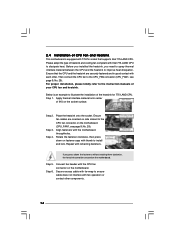
...steps. STEP 1: Install the SATA hard disks into the SATA hard disk, you want to the secondary SATA hard disk. If you the actual CPU host frequency in the fixed mode so that supports Serial ATA (SATA) hard disks. Please follow the order from up to bottom side to the...page 29. 2.10 Driver Installation Guide To install the drivers to your system, please insert the support CD to fixed AGP / PCI bus. Therefore, CPU FSB is untied during overclocking, FSB enjoys better margin due to your chassis. This section will guide you install can work properly. 2.11 Untied Overclocking...
...steps. STEP 1: Install the SATA hard disks into the SATA hard disk, you want to the secondary SATA hard disk. If you the actual CPU host frequency in the fixed mode so that supports Serial ATA (SATA) hard disks. Please follow the order from up to bottom side to the...page 29. 2.10 Driver Installation Guide To install the drivers to your system, please insert the support CD to fixed AGP / PCI bus. Therefore, CPU FSB is untied during overclocking, FSB enjoys better margin due to your chassis. This section will guide you install can work properly. 2.11 Untied Overclocking...
User Manual
Page 24
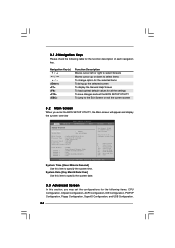
...the Exit Screen or exit the current screen 3.2 Main Screen When you may set the configurations for the following items: CPU Configuration, Chipset Configuration, ACPI Configuration, IDE Configuration, PCIPnP Configuration, Floppy Configuration, SuperIO Configuration, and USB Configuration. 24 ...Monitor Boot Security Exit System Overview System Time System Date [14:00:09] [Fri 05/19/2006] BIOS Version : ConRoe865PE BIOS P1.00 Processor Type : Intel (R) CPU 3.40 GHz (64bit supported) Processor Speed : 3400 MHz Cache Size : 1024KB Microcode Update : 0F34/17 Total Memory DIMM...
...the Exit Screen or exit the current screen 3.2 Main Screen When you may set the configurations for the following items: CPU Configuration, Chipset Configuration, ACPI Configuration, IDE Configuration, PCIPnP Configuration, Floppy Configuration, SuperIO Configuration, and USB Configuration. 24 ...Monitor Boot Security Exit System Overview System Time System Date [14:00:09] [Fri 05/19/2006] BIOS Version : ConRoe865PE BIOS P1.00 Processor Type : Intel (R) CPU 3.40 GHz (64bit supported) Processor Speed : 3400 MHz Cache Size : 1024KB Microcode Update : 0F34/17 Total Memory DIMM...
User Manual
Page 25
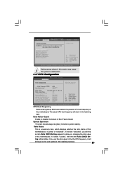
...Monitor Boot Security Exit Advanced Settings WARNING : Setting wrong values in below sections may cause the system to set the CPU host frequency. +F1 F9 F10 ESC Select Screen Select Item Change Option General Help Load Defaults Save and Exit Exit ...Intel (R) SpeedStep(tm) tech. [Disabled] [Disabled] [Enabled] [Enabled] [Disabled] [Enabled] [Auto] Select how to malfunction. 3.3.1 CPU Configuration BIOS SETUP UTILITY Advanced CPU Configuration CPU Host Frequency Actual Frequency (MHz) Boot Failure Guard Spread Spectrum [Auto] [200] [Enabled] [Auto] Ratio Status Unlocked (Max :17,...
...Monitor Boot Security Exit Advanced Settings WARNING : Setting wrong values in below sections may cause the system to set the CPU host frequency. +F1 F9 F10 ESC Select Screen Select Item Change Option General Help Load Defaults Save and Exit Exit ...Intel (R) SpeedStep(tm) tech. [Disabled] [Disabled] [Enabled] [Enabled] [Disabled] [Enabled] [Auto] Select how to malfunction. 3.3.1 CPU Configuration BIOS SETUP UTILITY Advanced CPU Configuration CPU Host Frequency Actual Frequency (MHz) Boot Failure Guard Spread Spectrum [Auto] [200] [Enabled] [Auto] Ratio Status Unlocked (Max :17,...
User Manual
Page 26
...changing the ratio value of this technology, such as "Portable/Laptop" to enable this option is unlocked, you will be hidden if the installed CPU does not support Hyper-Threading technology. Ratio CMOS Setting If the ratio status is set to [Enabled], a VMM (Virtual Machine Architecture) can .... NT4.0) cannot handle the function with "No Execute (NX) Memory Protection" can switch between multiple frequency and voltage points to keep the CPU from the chipset. When this function. 26 This option will be enabled in order to execute code. In the C1 power state, the processor...
...changing the ratio value of this technology, such as "Portable/Laptop" to enable this option is unlocked, you will be hidden if the installed CPU does not support Hyper-Threading technology. Ratio CMOS Setting If the ratio status is set to [Enabled], a VMM (Virtual Machine Architecture) can .... NT4.0) cannot handle the function with "No Execute (NX) Memory Protection" can switch between multiple frequency and voltage points to keep the CPU from the chipset. When this function. 26 This option will be enabled in order to execute code. In the C1 power state, the processor...
User Manual
Page 27
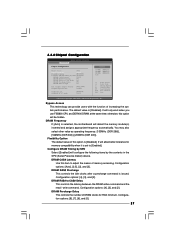
... the contents in the SPD (Serial Presence Detect) device. It will allow better tolerance for RAS minimum. It will only work when you use FSB800 CPU and DDR400 DRAM at the same time; Graphic Adapter Priority Graphics Aperture Size [PCI / AGP] [64MB] OnBoard LAN OnBoard AC'97 Audio [Enabled] [Auto] Options...
... the contents in the SPD (Serial Presence Detect) device. It will allow better tolerance for RAS minimum. It will only work when you use FSB800 CPU and DDR400 DRAM at the same time; Graphic Adapter Priority Graphics Aperture Size [PCI / AGP] [64MB] OnBoard LAN OnBoard AC'97 Audio [Enabled] [Auto] Options...
User Manual
Page 35
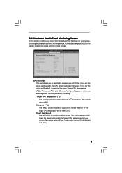
...to set the target fan speed. The default value is [Fast]. The default value is [2], which means the error of the CPU temperature, motherboard temperature, CPU fan speed, chassis fan speed, and the critical voltage. Target Fan Speed Use this option to monitor the status of the hardware ...Vcore + 3.30V + 5.00V + 12.00V : 45 C / 98 F : 31 C / 87 F : 2463 RPM : N/A : 1.384V : 3.306V : 5.067V : 11.890V CPU Quiet Fan Target CPU Temperature ( C) Tolerance ( C) Target Fan Speed [Enabled] [50] [02] [Fast] F1 F9 F10 ESC Select Screen Select Item General Help Load Defaults Save and Exit Exit ...
...to set the target fan speed. The default value is [Fast]. The default value is [2], which means the error of the CPU temperature, motherboard temperature, CPU fan speed, chassis fan speed, and the critical voltage. Target Fan Speed Use this option to monitor the status of the hardware ...Vcore + 3.30V + 5.00V + 12.00V : 45 C / 98 F : 31 C / 87 F : 2463 RPM : N/A : 1.384V : 3.306V : 5.067V : 11.890V CPU Quiet Fan Target CPU Temperature ( C) Tolerance ( C) Target Fan Speed [Enabled] [50] [02] [Fast] F1 F9 F10 ESC Select Screen Select Item General Help Load Defaults Save and Exit Exit ...
User Manual
Page 39
... The CD automatically displays the Main Menu if "AUTORUN" is enabled in this Live Demo, you start the installation of CPU and motherboard damages caused by improper handling, ASRock sincerely presents you a clear installation guide through the following path: ..\ Live Demo \ PC DIY \ LGA775INST_English.dat 4.2.5 ...Contact Information If you may find this "LGA 775 CPU Installation Live Demo". Click on the file "ASSETUP.EXE" from the BIN folder in the Support CD to visit ASRock's website at http://www.asrock.com; We hope you may check this live demo program before ...
... The CD automatically displays the Main Menu if "AUTORUN" is enabled in this Live Demo, you start the installation of CPU and motherboard damages caused by improper handling, ASRock sincerely presents you a clear installation guide through the following path: ..\ Live Demo \ PC DIY \ LGA775INST_English.dat 4.2.5 ...Contact Information If you may find this "LGA 775 CPU Installation Live Demo". Click on the file "ASSETUP.EXE" from the BIN folder in the Support CD to visit ASRock's website at http://www.asrock.com; We hope you may check this live demo program before ...
Quick Installation Guide
Page 2
... Audio Header (AUDIO1) 24 JR1 / JL1 Jumpers 25 PCI Slots (PCI1- 5) 26 BIOS FWH Chip 27 AGP Slot (1.5V_AGP1) 28 ATX Power Connector (ATXPWR1) 29 CPU Fan Connector (CPU_FAN1) 2 ASRock ConRoe865PE Motherboard Blue) 6 2 x 184-pin DDR DIMM Slots (Dual Channel B: DDR2, DDR4; Motherboard Layout English 1 PS2_USB_PWR1 Jumper 2 ATX 12V Connector (ATX12V1) 3 775-Pin...
... Audio Header (AUDIO1) 24 JR1 / JL1 Jumpers 25 PCI Slots (PCI1- 5) 26 BIOS FWH Chip 27 AGP Slot (1.5V_AGP1) 28 ATX Power Connector (ATXPWR1) 29 CPU Fan Connector (CPU_FAN1) 2 ASRock ConRoe865PE Motherboard Blue) 6 2 x 184-pin DDR DIMM Slots (Dual Channel B: DDR2, DDR4; Motherboard Layout English 1 PS2_USB_PWR1 Jumper 2 ATX 12V Connector (ATX12V1) 3 775-Pin...


