User Manual
Page 3
...2.8 Onboard Headers and Connectors 19 2.9 Serial ATA (SATA) Hard Disks Installation 22 2.10 Driver Installation Guide 22 2.11 Untied Overclocking Technology 22 3 BIOS SETUP UTILITY 23 3.1 Introduction 23 3.1.1 BIOS Menu Bar 23 3.1.2 Navigation Keys 24 3.2 Main Screen 24 3.3 Advanced Screen 24 3.3.1 CPU Configuration 25 3.3.2 Chipset Configuration 27 3.3.3 ACPI Configuration 28 3.3.4 IDE Configuration 29 3.3.5 PCIPnP Configuration 31 3.3.6 Floppy Configuration 32 3.3.7 Super IO Configuration 32 3.3.8 USB Configuration 34 3.4 Hardware Health Event Monitoring Screen 35 3.5 Boot...
...2.8 Onboard Headers and Connectors 19 2.9 Serial ATA (SATA) Hard Disks Installation 22 2.10 Driver Installation Guide 22 2.11 Untied Overclocking Technology 22 3 BIOS SETUP UTILITY 23 3.1 Introduction 23 3.1.1 BIOS Menu Bar 23 3.1.2 Navigation Keys 24 3.2 Main Screen 24 3.3 Advanced Screen 24 3.3.1 CPU Configuration 25 3.3.2 Chipset Configuration 27 3.3.3 ACPI Configuration 28 3.3.4 IDE Configuration 29 3.3.5 PCIPnP Configuration 31 3.3.6 Floppy Configuration 32 3.3.7 Super IO Configuration 32 3.3.8 USB Configuration 34 3.4 Hardware Health Event Monitoring Screen 35 3.5 Boot...
User Manual
Page 5
... manual occur, the updated version will be available on ASRock website as well. You may find the latest VGA cards and CPU support lists on ASRock website without notice. Chapter 3 and 4 contain the configuration guide to BIOS setup and information of the motherboard and step-bystep guide to quality and endurance. Chapter 1 Introduction Thank you for a 3.5-in Floppy Drive One Serial ATA (SATA) Data Cable (Optional) One Serial ATA (SATA) HDD Power Cable (Optional) One ASRock 8CH I/O Shield 5 In case...
... manual occur, the updated version will be available on ASRock website as well. You may find the latest VGA cards and CPU support lists on ASRock website without notice. Chapter 3 and 4 contain the configuration guide to BIOS setup and information of the motherboard and step-bystep guide to quality and endurance. Chapter 1 Introduction Thank you for a 3.5-in Floppy Drive One Serial ATA (SATA) Data Cable (Optional) One Serial ATA (SATA) HDD Power Cable (Optional) One ASRock 8CH I/O Shield 5 In case...
User Manual
Page 8
... use a FSB1066-CPU on the motherboard functions properly and unplug the power cord, then plug it back again. However, if you install the PC system. 8. This motherboard supports Dual Channel Memory Technology. Although this motherboard, it is to support FSB1066 CPU, please adjust your FSB1 jumper setting, and short pin2 and pin3 (see page 18). 2. Frequencies other than the recommended CPU bus frequencies may cause permanent damage! 9. While CPU overheat is only supported by overclocking mode...
... use a FSB1066-CPU on the motherboard functions properly and unplug the power cord, then plug it back again. However, if you install the PC system. 8. This motherboard supports Dual Channel Memory Technology. Although this motherboard, it is to support FSB1066 CPU, please adjust your FSB1 jumper setting, and short pin2 and pin3 (see page 18). 2. Frequencies other than the recommended CPU bus frequencies may cause permanent damage! 9. While CPU overheat is only supported by overclocking mode...
User Manual
Page 9
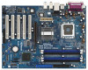
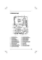
... USB 2.0 Header (USB45, Blue) 20 Floppy Connector (FLOPPY1) 21 Game Connector (GAME1) 22 Internal Audio Connector: CD1 (Black) 23 Front Panel Audio Header (AUDIO1) 24 JR1 / JL1 Jumpers 25 PCI Slots (PCI1- 5) 26 BIOS FWH Chip 27 AGP Slot (1.5V_AGP1) 28 ATX Power Connector (ATXPWR1) 29 CPU Fan Connector (CPU_FAN1) 9 Blue) 6 2 x 184-pin DDR DIMM Slots (Dual Channel B: DDR2, DDR4; 1.3 Motherboard Layout 12 PS2 Mouse 1 PS2_USB_PWR1 ATX12V1 3 4 22.9cm (9.0 in) 56 PARALLEL PORT PS2 Keyboard Presler Conroe COM1 DDR3 (64/72 bit...
... USB 2.0 Header (USB45, Blue) 20 Floppy Connector (FLOPPY1) 21 Game Connector (GAME1) 22 Internal Audio Connector: CD1 (Black) 23 Front Panel Audio Header (AUDIO1) 24 JR1 / JL1 Jumpers 25 PCI Slots (PCI1- 5) 26 BIOS FWH Chip 27 AGP Slot (1.5V_AGP1) 28 ATX Power Connector (ATXPWR1) 29 CPU Fan Connector (CPU_FAN1) 9 Blue) 6 2 x 184-pin DDR DIMM Slots (Dual Channel B: DDR2, DDR4; 1.3 Motherboard Layout 12 PS2 Mouse 1 PS2_USB_PWR1 ATX12V1 3 4 22.9cm (9.0 in) 56 PARALLEL PORT PS2 Keyboard Presler Conroe COM1 DDR3 (64/72 bit...
User Manual
Page 20
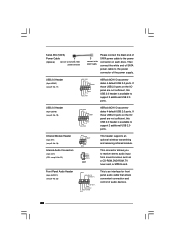
... drive. If those USB 2.0 ports on the I/O panel are not sufficient, this USB 2.0 header is available to the power connector on the I/O panel are not sufficient, this USB 2.0 header is an interface for front panel audio cable that allows convenient connection and control of audio devices. 20 Then connect the white end of SATA power cable to receive stereo audio input from sound sources such as a CD-ROM, DVD-ROM, TV tuner card, or MPEG card. Serial ATA (SATA) Power Cable (Optional) connect to the SATA HDD power connector connect...
... drive. If those USB 2.0 ports on the I/O panel are not sufficient, this USB 2.0 header is available to the power connector on the I/O panel are not sufficient, this USB 2.0 header is an interface for front panel audio cable that allows convenient connection and control of audio devices. 20 Then connect the white end of SATA power cable to receive stereo audio input from sound sources such as a CD-ROM, DVD-ROM, TV tuner card, or MPEG card. Serial ATA (SATA) Power Cable (Optional) connect to the SATA HDD power connector connect...
User Manual
Page 22
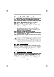
... install SATA hard disks on this step. STEP 5: Connect the SATA power cable to install those required drivers. You may set "CPU Host Frequency" option of your chassis. Therefore, the drivers you to the motherboard's primary SATA connector (SATA1). For the configuration details, please refer to the instruction on the support CD driver page. 2.9 Serial ATA (SATA) Hard Disks Installation This motherboard adopts Intel® ICH5 south bridge chipset that FSB can operate under a more stable overclocking environment. 22 Then, the drivers compatible...
... install SATA hard disks on this step. STEP 5: Connect the SATA power cable to install those required drivers. You may set "CPU Host Frequency" option of your chassis. Therefore, the drivers you to the motherboard's primary SATA connector (SATA1). For the configuration details, please refer to the instruction on the support CD driver page. 2.9 Serial ATA (SATA) Hard Disks Installation This motherboard adopts Intel® ICH5 south bridge chipset that FSB can operate under a more stable overclocking environment. 22 Then, the drivers compatible...
User Manual
Page 23
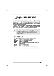
... use the BIOS SETUP UTILITY to configure your screen. 3.1.1 BIOS Menu Bar The top of the screen has a menu bar with its test routines. You may also restart by pressing the reset button on the motherboard stores the BIOS SETUP UTILITY. Because the BIOS software is constantly being updated, the following selections: Main To set up the system time/date information Advanced To set up the advanced BIOS features PCIPnP To set up the PCI...
... use the BIOS SETUP UTILITY to configure your screen. 3.1.1 BIOS Menu Bar The top of the screen has a menu bar with its test routines. You may also restart by pressing the reset button on the motherboard stores the BIOS SETUP UTILITY. Because the BIOS software is constantly being updated, the following selections: Main To set up the system time/date information Advanced To set up the advanced BIOS features PCIPnP To set up the PCI...
User Manual
Page 25
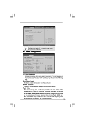
... State Max CPUID Value Limit Intel (R) Virtualization tech. BIOS SETUP UTILITY Main Advanced H/W Monitor Boot Security Exit Advanced Settings WARNING : Setting wrong values in below sections may cause the system to allow you changing the ratio value of this motherboard. Boot Failure Guard Enable or disable the feature of this motherboard. CPU Configuration Chipset Configuration ACPI Configuration IDE Configuration PCIPnP Configuration Floppy Configuration SuperIO Configuration USB Configuration Configure CPU Select Screen Select Item Enter Go to set the CPU host frequency...
... State Max CPUID Value Limit Intel (R) Virtualization tech. BIOS SETUP UTILITY Main Advanced H/W Monitor Boot Security Exit Advanced Settings WARNING : Setting wrong values in below sections may cause the system to allow you changing the ratio value of this motherboard. Boot Failure Guard Enable or disable the feature of this motherboard. CPU Configuration Chipset Configuration ACPI Configuration IDE Configuration PCIPnP Configuration Floppy Configuration SuperIO Configuration USB Configuration Configure CPU Select Screen Select Item Enter Go to set the CPU host frequency...
User Manual
Page 26
... supported through the native processor instructions HLT and MWAIT and requires no hardware support from being used by Vanderpool Technology. An IA-32 processor with "No Execute (NX) Memory Protection" can utilize the additional hardware capabilities provided by malicious software to execute code. Processor can switch between multiple frequency and voltage points to [Enabled], a VMM (Virtual Machine Architecture) can prevent data pages from the chipset. Intel (R) Virtualization tech. Set to boot legacy...
... supported through the native processor instructions HLT and MWAIT and requires no hardware support from being used by Vanderpool Technology. An IA-32 processor with "No Execute (NX) Memory Protection" can utilize the additional hardware capabilities provided by malicious software to execute code. Processor can switch between multiple frequency and voltage points to [Enabled], a VMM (Virtual Machine Architecture) can prevent data pages from the chipset. Intel (R) Virtualization tech. Set to boot legacy...
User Manual
Page 28
... AC/Power Loss Use this item to enable or disable PS/2 keyboard to a section of the PCI memory address range used for the onboard AC'97 Audio feature. 3.3.3 ACPI Configuration BIOS SETUP UTILITY Advanced ACPI Configuration Suspend To RAM Restore on AC / Power Loss Ring-In Power On PCI Devices Power On PS / 2 Keyboard Power On RTC Alarm Power On [Disabled] [Power Off] [Disabled] [Disabled] [Disabled] [Disabled] Select auto-detect or disable the STR feature. +F1 F9 F10 ESC Select Screen Select Item Change Option General Help Load Defaults...
... AC/Power Loss Use this item to enable or disable PS/2 keyboard to a section of the PCI memory address range used for the onboard AC'97 Audio feature. 3.3.3 ACPI Configuration BIOS SETUP UTILITY Advanced ACPI Configuration Suspend To RAM Restore on AC / Power Loss Ring-In Power On PCI Devices Power On PS / 2 Keyboard Power On RTC Alarm Power On [Disabled] [Power Off] [Disabled] [Disabled] [Disabled] [Disabled] Select auto-detect or disable the STR feature. +F1 F9 F10 ESC Select Screen Select Item Change Option General Help Load Defaults...
User Manual
Page 29
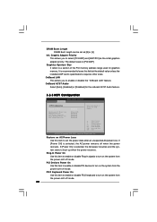
... Alarm Power On Use this item to enable or disable RTC (Real Time Clock) to power on the "OnBoard IDE Operate Mode" ([Compatible Mode] or [Enhanced Mode]) that the following options will be varied depending on the system. 3.3.4 IDE Configuration BIOS SETUP UTILITY Advanced IDE Configuration OnBoard IDE Operate Mode OnBoard IDE Controller Primary IDE Master Primary IDE Slave Secondary IDE Master Secondary IDE Slave SATA1 SATA2 [Enhanced Mode] [Both] [Hard Disk] [Not Detected] [Not Detected] [Not Detected] [Not Detected] [Not Detected] Set [Compatible Mode] when...
... Alarm Power On Use this item to enable or disable RTC (Real Time Clock) to power on the "OnBoard IDE Operate Mode" ([Compatible Mode] or [Enhanced Mode]) that the following options will be varied depending on the system. 3.3.4 IDE Configuration BIOS SETUP UTILITY Advanced IDE Configuration OnBoard IDE Operate Mode OnBoard IDE Controller Primary IDE Master Primary IDE Slave Secondary IDE Master Secondary IDE Slave SATA1 SATA2 [Enhanced Mode] [Both] [Hard Disk] [Not Detected] [Not Detected] [Not Detected] [Not Detected] [Not Detected] Set [Compatible Mode] when...
User Manual
Page 31
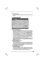
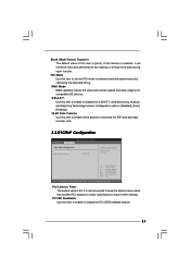
... by optimizing the hard disk timing. Configuration options: [Disabled], [Auto], [Enabled]. 32-Bit Data Transfer Use this item to enable 32-bit access to maximize the IDE hard disk data transfer rate. 3.3.5 PCIPnP Configuration BIOS SETUP UTILITY Advanced PCI / PnP Configuration PCI Latency Timer PCI IDE BusMaster [32] [Enabled] Value in units of this item to enable or disable the S.M.A.R.T. (Self-Monitoring, Analysis, and Reporting Technology) feature. Use this feature is 32. Block (Multi-Sector Transfer) The default value of PCI clocks for compatible IDE devices.
... by optimizing the hard disk timing. Configuration options: [Disabled], [Auto], [Enabled]. 32-Bit Data Transfer Use this item to enable 32-bit access to maximize the IDE hard disk data transfer rate. 3.3.5 PCIPnP Configuration BIOS SETUP UTILITY Advanced PCI / PnP Configuration PCI Latency Timer PCI IDE BusMaster [32] [Enabled] Value in units of this item to enable or disable the S.M.A.R.T. (Self-Monitoring, Analysis, and Reporting Technology) feature. Use this feature is 32. Block (Multi-Sector Transfer) The default value of PCI clocks for compatible IDE devices.
User Manual
Page 32
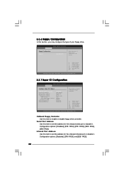
... Use this section, you may configure the type of floppy drive connected to the system. +F1 F9 F10 ESC Select Screen Select Item Change Option General Help Load Defaults Save and Exit Exit v02.54 (C) Copyright 1985-2003, American Megatrends, Inc. 3.3.7 Super IO Configuration BIOS SETUP UTILITY Advanced Configure Super IO Chipset OnBoard Floppy Controller Serial Port Address Infrared Port Address Parallel Port Address Parallel Port Mode EPP Version ECP Mode DMA Channel Parallel Port IRQ Onboard Game Port Onboard MIDI Port [Enabled] [3F8 / IRQ4] [Disabled...
... Use this section, you may configure the type of floppy drive connected to the system. +F1 F9 F10 ESC Select Screen Select Item Change Option General Help Load Defaults Save and Exit Exit v02.54 (C) Copyright 1985-2003, American Megatrends, Inc. 3.3.7 Super IO Configuration BIOS SETUP UTILITY Advanced Configure Super IO Chipset OnBoard Floppy Controller Serial Port Address Infrared Port Address Parallel Port Address Parallel Port Mode EPP Version ECP Mode DMA Channel Parallel Port IRQ Onboard Game Port Onboard MIDI Port [Enabled] [3F8 / IRQ4] [Disabled...
User Manual
Page 34
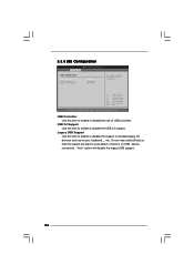
...emulate legacy I/O devices such as mouse, keyboard,... etc. Legacy USB Support Use this item to auto-detect; 3.3.8 USB Configuration BIOS SETUP UTILITY Advanced USB Configuration USB Controller USB 2.0 Support Legacy USB Support [Enabled] [Enabled] [Disabled] To enable or disable the onboard USB controllers. +F1 F9 F10 ESC Select Screen Select Item Change Option General Help Load Defaults Save and Exit Exit v02.54 (C) Copyright 1985-2003, American Megatrends, Inc. USB 2.0 Support Use this item to enable or disable the support to enable or disable the use of USB controller. Or...
...emulate legacy I/O devices such as mouse, keyboard,... etc. Legacy USB Support Use this item to auto-detect; 3.3.8 USB Configuration BIOS SETUP UTILITY Advanced USB Configuration USB Controller USB 2.0 Support Legacy USB Support [Enabled] [Enabled] [Disabled] To enable or disable the onboard USB controllers. +F1 F9 F10 ESC Select Screen Select Item Change Option General Help Load Defaults Save and Exit Exit v02.54 (C) Copyright 1985-2003, American Megatrends, Inc. USB 2.0 Support Use this item to enable or disable the support to enable or disable the use of USB controller. Or...
User Manual
Page 37
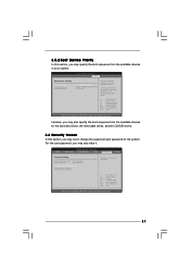
... FLOPPY DRIVE] [HDD: PM-MAXTOR 6L08] [CD / DVD] Specifies the boot sequence from the available devices. A device enclosed in parenthesis has been disabled in your system. Likewise, you may also specify the boot sequence from the available devices for the system. BIOS SETUP UTILITY Main Advanced H/W Monitor Boot Security Exit Security Settings Supervisor Password : Not Installed User Password : Not Installed Change Supervisor Password Change User Password Clear User Password Install or Change the password. Select Screen Select Item Enter Change F1 General Help F9 Load Defaults...
... FLOPPY DRIVE] [HDD: PM-MAXTOR 6L08] [CD / DVD] Specifies the boot sequence from the available devices. A device enclosed in parenthesis has been disabled in your system. Likewise, you may also specify the boot sequence from the available devices for the system. BIOS SETUP UTILITY Main Advanced H/W Monitor Boot Security Exit Security Settings Supervisor Password : Not Installed User Password : Not Installed Change Supervisor Password Change User Password Clear User Password Install or Change the password. Select Screen Select Item Enter Change F1 General Help F9 Load Defaults...
User Manual
Page 39
... / XP 64-bit. Refer to play the file. The CD automatically displays the Main Menu if "AUTORUN" is a new CPU socket interface that the motherboard supports. If the Main Menu did not appear automatically, locate and double click on a specific item then follow the installation wizard to install it has several tiny pins, whcih are easily to activate the devices. 4.2.3 Utilities Menu The Utilities Menu shows the applications software that Intel has...
... / XP 64-bit. Refer to play the file. The CD automatically displays the Main Menu if "AUTORUN" is a new CPU socket interface that the motherboard supports. If the Main Menu did not appear automatically, locate and double click on a specific item then follow the installation wizard to install it has several tiny pins, whcih are easily to activate the devices. 4.2.3 Utilities Menu The Utilities Menu shows the applications software that Intel has...
Quick Installation Guide
Page 7
... to short pin1 and pin2. English 7 ASRock ConRoe865PE Motherboard The default setting of this motherboard! Before you implement Dual Channel Memory Technology, make sure that you adopt a DDR333 memory module. Before you install the PC system. 8. Before installing FSB1066 CPU, please make sure to perform over-clocking. CPU FSB Frequency Memory Support Frequency 800 DDR266, DDR333*, DDR400 533 DDR266, DDR333 1066 DDR400* * When you use a FSB1066-CPU on page 11 for proper connection. 10...
... to short pin1 and pin2. English 7 ASRock ConRoe865PE Motherboard The default setting of this motherboard! Before you implement Dual Channel Memory Technology, make sure that you adopt a DDR333 memory module. Before you install the PC system. 8. Before installing FSB1066 CPU, please make sure to perform over-clocking. CPU FSB Frequency Memory Support Frequency 800 DDR266, DDR333*, DDR400 533 DDR266, DDR333 1066 DDR400* * When you use a FSB1066-CPU on page 11 for proper connection. 10...

Quick Installation Guide
Page 17
... front panel functions. Please connect an ATX power supply to this header. Connect a Game cable to this connector so that it can provides sufficient power. Please connect the chassis speaker to this connector if the Game port bracket is necessary to connect a power supply with ATX 12V plug to the ground pin. Please connect a chassis fan cable to this connector and match the black wire to this connector. Please connect a CPU fan cable to this connector and match the black wire to power up. 17 ASRock ConRoe865PE Motherboard...
... front panel functions. Please connect an ATX power supply to this header. Connect a Game cable to this connector so that it can provides sufficient power. Please connect the chassis speaker to this connector if the Game port bracket is necessary to connect a power supply with ATX 12V plug to the ground pin. Please connect a chassis fan cable to this connector and match the black wire to this connector. Please connect a CPU fan cable to this connector and match the black wire to power up. 17 ASRock ConRoe865PE Motherboard...
Quick Installation Guide
Page 18
... motherboard for internal storage devices. Then, the drivers compatible to the condition of the OnBoard IDE Operate Mode option in the following steps. STEP 7: Connect the other end of the SATA data cable to the primary SATA hard disk. STEP 4: Connect the other end of the SATA data cable to the secondary SATA hard disk. 2.7 Serial ATA (SATA) Hard Disks Installation This motherboard adopts Intel® ICH5 south bridge chipset that FSB can work properly. 2.9 Untied Overclocking Technology This motherboard supports Untied Overclocking Technology, which will guide...
... motherboard for internal storage devices. Then, the drivers compatible to the condition of the OnBoard IDE Operate Mode option in the following steps. STEP 7: Connect the other end of the SATA data cable to the primary SATA hard disk. STEP 4: Connect the other end of the SATA data cable to the secondary SATA hard disk. 2.7 Serial ATA (SATA) Hard Disks Installation This motherboard adopts Intel® ICH5 south bridge chipset that FSB can work properly. 2.9 Untied Overclocking Technology This motherboard supports Untied Overclocking Technology, which will guide...
Quick Installation Guide
Page 19
... installation of CPU and motherboard damages caused by improper handling, ASRock sincerely presents you a clear installation guide through the following path: ..\ MPEGAV \ LGA775INST.DAT 19 ASRock ConRoe865PE Motherboard English otherwise, POST continues with the motherboard contains necessary drivers and useful utilities that Intel has released. To begin using the Support CD, insert the CD into your computer. We hope you start up the computer, please press during the Power...
... installation of CPU and motherboard damages caused by improper handling, ASRock sincerely presents you a clear installation guide through the following path: ..\ MPEGAV \ LGA775INST.DAT 19 ASRock ConRoe865PE Motherboard English otherwise, POST continues with the motherboard contains necessary drivers and useful utilities that Intel has released. To begin using the Support CD, insert the CD into your computer. We hope you start up the computer, please press during the Power...


