User Manual
Page 8
... Overclocking Technology" on updating now. Frequencies other than 4GB for the reservation for details. 4. While CPU overheat is not recommended to 115MHz. 2. For audio output, this motherboard supports both stereo and mono modes. You can also connect SATA hard disk to spray thermal grease between the CPU and the heatsink when you use a FSB1333-CPU on page 11 for USB 2.0 works fine under Windows® XP, Windows® XP 64-bit, Windows®...
... Overclocking Technology" on updating now. Frequencies other than 4GB for the reservation for details. 4. While CPU overheat is not recommended to 115MHz. 2. For audio output, this motherboard supports both stereo and mono modes. You can also connect SATA hard disk to spray thermal grease between the CPU and the heatsink when you use a FSB1333-CPU on page 11 for USB 2.0 works fine under Windows® XP, Windows® XP 64-bit, Windows®...
User Manual
Page 10
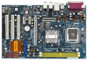
... Panel Audio Header (HD_AUDIO1) 26 HDMI_SPDIF Header (HDMI_SPDIF1) 27 PCI Slots (PCI1- 3) 28 BIOS FWH Chip 29 PCI Express x1 Slot (PCIE3) 30 PCI Express x1 Slot (PCIE2) 10 Yellow) 8 PCI Express x16 Slot (PCIE1) 9 Clear CMOS Jumper (CLRCMOS1) 10 IDE1 Connector (IDE1, Blue) 11 SATAII Connector (SATAII_3 (PORT2); Orange) 13 SATAII Connector (SATAII_2 (PORT1); 1.4 Motherboard Layout PS2 Keyboard 1 23 4 19.1cm (7.5 in) PS2 Mouse 1 PS2_USB_PWR1 ATX12V1 56 CPU_FAN1 PARALLEL PORT Dual Core CPU Conroe COM1 DDRII_2 (64/72 bit, 240-pin...
... Panel Audio Header (HD_AUDIO1) 26 HDMI_SPDIF Header (HDMI_SPDIF1) 27 PCI Slots (PCI1- 3) 28 BIOS FWH Chip 29 PCI Express x1 Slot (PCIE3) 30 PCI Express x1 Slot (PCIE2) 10 Yellow) 8 PCI Express x16 Slot (PCIE1) 9 Clear CMOS Jumper (CLRCMOS1) 10 IDE1 Connector (IDE1, Blue) 11 SATAII Connector (SATAII_3 (PORT2); Orange) 13 SATAII Connector (SATAII_2 (PORT1); 1.4 Motherboard Layout PS2 Keyboard 1 23 4 19.1cm (7.5 in) PS2 Mouse 1 PS2_USB_PWR1 ATX12V1 56 CPU_FAN1 PARALLEL PORT Dual Core CPU Conroe COM1 DDRII_2 (64/72 bit, 240-pin...
User Manual
Page 20
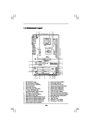
... 1 GND P+4 P-4 USB_PWR Infrared Module Header (5-pin IR1) (see p.10 No. 18) Internal Audio Connectors (4-pin CD1) (CD1: see p.10 No. 20) USB_PWR P-7 P+7 GND DUMMY 1 GND P+6 P-6 USB_PWR Besides four default USB 2.0 ports on the I/O panel, there are two USB 2.0 headers on this motherboard. This connector allows you to function correctly. Serial ATA (SATA) Power Cable (Optional) connect to the SATA HDD power connector connect to the power supply Please connect the black end of audio devices. 1. USB 2.0 Headers (9-pin USB67) (see p.10 No. 24...
... 1 GND P+4 P-4 USB_PWR Infrared Module Header (5-pin IR1) (see p.10 No. 18) Internal Audio Connectors (4-pin CD1) (CD1: see p.10 No. 20) USB_PWR P-7 P+7 GND DUMMY 1 GND P+6 P-6 USB_PWR Besides four default USB 2.0 ports on the I/O panel, there are two USB 2.0 headers on this motherboard. This connector allows you to function correctly. Serial ATA (SATA) Power Cable (Optional) connect to the SATA HDD power connector connect to the power supply Please connect the black end of audio devices. 1. USB 2.0 Headers (9-pin USB67) (see p.10 No. 24...

User Manual
Page 23
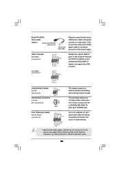
... the VGA card user manual for detailed connection procedures. A complete HDMI system requires a HDMI VGA card and a HDMI ready motherboard with a HDMI_SPDIF header, which provides an interface between any compatible digital audio/ video source, such as a set-top box, DVD player, A/V receiver and a compatible digital audio or video monitor, such as HDTV. Install the HDMI VGA card to the• PCI Express Graphics slot on HDMI VGA card to the HDMI_SPDIF connector of HDMI VGA card or other VGA card. Please choose the appropriate white end according to HDMI device...
... the VGA card user manual for detailed connection procedures. A complete HDMI system requires a HDMI VGA card and a HDMI ready motherboard with a HDMI_SPDIF header, which provides an interface between any compatible digital audio/ video source, such as a set-top box, DVD player, A/V receiver and a compatible digital audio or video monitor, such as HDTV. Install the HDMI VGA card to the• PCI Express Graphics slot on HDMI VGA card to the HDMI_SPDIF connector of HDMI VGA card or other VGA card. Please choose the appropriate white end according to HDMI device...
User Manual
Page 25
... 2: Connect the SATA power cable to the motherboard's SATAII connector. STEP 3: Connect one end of your system can be auto-detected and listed on the support CD driver page. Therefore, CPU FSB is untied during overclocking, but PCI / PCIE buses are in the fixed mode so that supports Serial ATA (SATA) / Serial ATAII (SATAII) hard disks. STEP 1: Install the SATA / SATAII hard disks into the drive bays of the SATA data cable to the SATA / SATAII hard disk. Therefore, the drivers you enable Untied Overclocking...
... 2: Connect the SATA power cable to the motherboard's SATAII connector. STEP 3: Connect one end of your system can be auto-detected and listed on the support CD driver page. Therefore, CPU FSB is untied during overclocking, but PCI / PCIE buses are in the fixed mode so that supports Serial ATA (SATA) / Serial ATAII (SATAII) hard disks. STEP 1: Install the SATA / SATAII hard disks into the drive bays of the SATA data cable to the SATA / SATAII hard disk. Therefore, the drivers you enable Untied Overclocking...
User Manual
Page 28
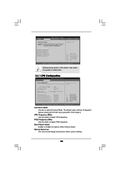
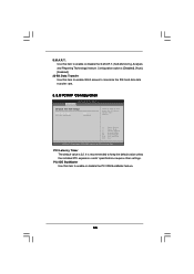
.... CPU Frequency (MHz) Use this to select Overclock Mode. Overclock Mode Use this option to adjust CPU frequency. CPU Configuration Chipset Configuration ACPI Configuration IDE Configuration PCIPnP Configuration Floppy Configuration SuperIO Configuration USB Configuration Configure CPU Select Screen Select Item Enter Go to adjust PCIE frequency. PCIE Frequency (MHz) Use this option to Sub Screen F1 General Help F9 Load Defaults F10 Save and Exit ESC Exit v02.54 (C) Copyright 1985-2005, American Megatrends, Inc. The default value is [Auto]. Boot Failure Guard Enable or disable the...
.... CPU Frequency (MHz) Use this to select Overclock Mode. Overclock Mode Use this option to adjust CPU frequency. CPU Configuration Chipset Configuration ACPI Configuration IDE Configuration PCIPnP Configuration Floppy Configuration SuperIO Configuration USB Configuration Configure CPU Select Screen Select Item Enter Go to adjust PCIE frequency. PCIE Frequency (MHz) Use this option to Sub Screen F1 General Help F9 Load Defaults F10 Save and Exit ESC Exit v02.54 (C) Copyright 1985-2005, American Megatrends, Inc. The default value is [Auto]. Boot Failure Guard Enable or disable the...

User Manual
Page 29
.... When this motherboard. CPU Thermal Throttling You may select [Enabled] to enable P4 CPU internal thermal control mechanism to [Enabled], a VMM (Virtual Machine Architecture) can prevent data pages from being used by Vanderpool Technology. An IA-32 processor with extended CPUID functions. Set to execute code. If it requires a computer system with disable. Ratio CMOS Setting If the ratio status is set to keep the CPU from the chipset. Ratio...
.... When this motherboard. CPU Thermal Throttling You may select [Enabled] to enable P4 CPU internal thermal control mechanism to [Enabled], a VMM (Virtual Machine Architecture) can prevent data pages from being used by Vanderpool Technology. An IA-32 processor with extended CPUID functions. Set to execute code. If it requires a computer system with disable. Ratio CMOS Setting If the ratio status is set to keep the CPU from the chipset. Ratio...
User Manual
Page 30
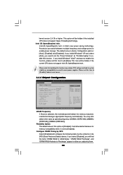
... compatibility issue with some power supplies. If you select [Disabled], you will allow you install Windows® VistaTM and want to enable this function, please set this item to allow better tolerance for memory compatibility when it is selected, the motherboard will configure the following items by SPD [Enabled] DRAM CAS# Latency [Auto] Advanced DRAM Configuration [Auto] Primary Graphics Adapter [PCI] OnBoard HD Audio Front Panel CD-In OnBoard Lan [Auto] [Auto] [Enabled] [Enabled] PCI Fix Function [Enabled] VCCM Voltage +1.5V Voltage [Auto] [Normal] Options Auto...
... compatibility issue with some power supplies. If you select [Disabled], you will allow you install Windows® VistaTM and want to enable this function, please set this item to allow better tolerance for memory compatibility when it is selected, the motherboard will configure the following items by SPD [Enabled] DRAM CAS# Latency [Auto] Advanced DRAM Configuration [Auto] Primary Graphics Adapter [PCI] OnBoard HD Audio Front Panel CD-In OnBoard Lan [Auto] [Auto] [Enabled] [Enabled] PCI Fix Function [Enabled] VCCM Voltage +1.5V Voltage [Auto] [Normal] Options Auto...
User Manual
Page 31
... Windows® VistaTM logo test, please disable this to select VCCM Voltage. If this feature is [Normal]. 31 The default value of this item is set to [Disabled], PCI clock can be fixed at 33.3 MHz. DRAM CAS# Latency Use this item is set to [Enabled], PCI frequency can be synchronized to PCIE clock. If this item to enable or disable CD-In of memory accessing. Configuration options: [High], [Normal], [Low], and [Auto]. Configuration options: [PCI] and [PCI Express]. OnBoard Lan...
... Windows® VistaTM logo test, please disable this to select VCCM Voltage. If this feature is [Normal]. 31 The default value of this item is set to [Disabled], PCI clock can be fixed at 33.3 MHz. DRAM CAS# Latency Use this item is set to [Enabled], PCI frequency can be synchronized to PCIE clock. If this item to enable or disable CD-In of memory accessing. Configuration options: [High], [Normal], [Low], and [Auto]. Configuration options: [PCI] and [PCI Express]. OnBoard Lan...
User Manual
Page 35
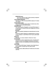
... IDE hard disk data transfer rate. 3.3.5 PCIPnP Configuration BIOS SETUP UTILITY Advanced Advanced PCI / PnP Settings PCI Latency Timer PCI IDE BusMaster [32] [Enabled] Value in units of PCI clocks for PCI device latency timer register. +F1 F9 F10 ESC Select Screen Select Item Change Option General Help Load Defaults Save and Exit Exit v02.54 (C) Copyright 1985-2005, American Megatrends, Inc. Configuration options: [Disabled], [Auto], [Enabled]. 32-Bit Data Transfer Use this item to enable 32-bit access to keep the default...
... IDE hard disk data transfer rate. 3.3.5 PCIPnP Configuration BIOS SETUP UTILITY Advanced Advanced PCI / PnP Settings PCI Latency Timer PCI IDE BusMaster [32] [Enabled] Value in units of PCI clocks for PCI device latency timer register. +F1 F9 F10 ESC Select Screen Select Item Change Option General Help Load Defaults Save and Exit Exit v02.54 (C) Copyright 1985-2005, American Megatrends, Inc. Configuration options: [Disabled], [Auto], [Enabled]. 32-Bit Data Transfer Use this item to enable 32-bit access to keep the default...
User Manual
Page 38
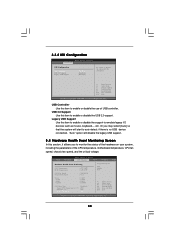
... Health Event Monitoring Screen In this item to emulate legacy I/O devices such as mouse, keyboard,... USB Controller Use this section, it allows you may select [Auto] so that the system will start to monitor the status of the hardware on your system, including the parameters of USB controller. 3.3.8 USB Configuration BIOS SETUP UTILITY Advanced USB Configuration USB Controller USB 2.0 Support Legacy USB Support [Enabled] [Enabled] [Disabled] To enable or disable the onboard USB controllers. +F1 F9 F10 ESC Select Screen Select Item Change Option General Help Load Defaults Save...
... Health Event Monitoring Screen In this item to emulate legacy I/O devices such as mouse, keyboard,... USB Controller Use this section, it allows you may select [Auto] so that the system will start to monitor the status of the hardware on your system, including the parameters of USB controller. 3.3.8 USB Configuration BIOS SETUP UTILITY Advanced USB Configuration USB Controller USB 2.0 Support Legacy USB Support [Enabled] [Enabled] [Disabled] To enable or disable the onboard USB controllers. +F1 F9 F10 ESC Select Screen Select Item Change Option General Help Load Defaults Save...
User Manual
Page 40
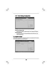
... BIOS SETUP UTILITY Boot Boot Settings Configuration Boot From Onboard LAN Bootup Num-Lock [Disabled] [On] To enable or disable the boot from network feature. +F1 F9 F10 ESC Select Screen Select Item Change Option General Help Load Defaults Save and Exit Exit v02.54 (C) Copyright 1985-2005, American Megatrends, Inc. BIOS SETUP UTILITY Main Advanced H/W Monitor Boot Security Exit Security Settings Supervisor Password : Not Installed User Password : Not Installed Change Supervisor Password Change User Password Install or Change the password. Boot From Onboard LAN Use...
... BIOS SETUP UTILITY Boot Boot Settings Configuration Boot From Onboard LAN Bootup Num-Lock [Disabled] [On] To enable or disable the boot from network feature. +F1 F9 F10 ESC Select Screen Select Item Change Option General Help Load Defaults Save and Exit Exit v02.54 (C) Copyright 1985-2005, American Megatrends, Inc. BIOS SETUP UTILITY Main Advanced H/W Monitor Boot Security Exit Security Settings Supervisor Password : Not Installed User Password : Not Installed Change Supervisor Password Change User Password Install or Change the password. Boot From Onboard LAN Use...
User Manual
Page 42
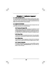
... your CD-ROM drive. If the Main Menu did not appear automatically, locate and double click on a specific item then follow the installation wizard to visit ASRock's website at http://www.asrock.com; or you need to contact ASRock or want to activate the devices. 4.2.3 Utilities Menu The Utilities Menu shows the applications software that enhance the motherboard features. 4.2.1 Running The Support CD To begin using the support CD, insert...
... your CD-ROM drive. If the Main Menu did not appear automatically, locate and double click on a specific item then follow the installation wizard to visit ASRock's website at http://www.asrock.com; or you need to contact ASRock or want to activate the devices. 4.2.3 Utilities Menu The Utilities Menu shows the applications software that enhance the motherboard features. 4.2.1 Running The Support CD To begin using the support CD, insert...

Quick Installation Guide
Page 2
... Game Port Header (GAME1) 24 Internal Audio Connector: CD1 (Black) 25 Front Panel Audio Header (HD_AUDIO1) 26 HDMI_SPDIF Header (HDMI_SPDIF1) 27 PCI Slots (PCI1- 3) 28 BIOS FWH Chip 29 PCI Express x1 Slot (PCIE3) 30 PCI Express x1 Slot (PCIE2) 2 ASRock ConRoe1333-GLAN Motherboard Motherboard Layout English 1 PS2_USB_PWR1 Jumper 2 ATX 12V Connector (ATX12V1) 3 ATX Power Connector (ATXPWR1) 4 775-Pin CPU Socket 5 North Bridge Controller 6 CPU Fan Connector (CPU_FAN1) 7 2 x 240-pin DDRII DIMM Slots (Dual Channel: DDRII_1, DDRII_2; Yellow) 8 PCI Express x16 Slot (PCIE1) 9 Clear CMOS Jumper...
... Game Port Header (GAME1) 24 Internal Audio Connector: CD1 (Black) 25 Front Panel Audio Header (HD_AUDIO1) 26 HDMI_SPDIF Header (HDMI_SPDIF1) 27 PCI Slots (PCI1- 3) 28 BIOS FWH Chip 29 PCI Express x1 Slot (PCIE3) 30 PCI Express x1 Slot (PCIE2) 2 ASRock ConRoe1333-GLAN Motherboard Motherboard Layout English 1 PS2_USB_PWR1 Jumper 2 ATX 12V Connector (ATX12V1) 3 ATX Power Connector (ATXPWR1) 4 775-Pin CPU Socket 5 North Bridge Controller 6 CPU Fan Connector (CPU_FAN1) 7 2 x 240-pin DDRII DIMM Slots (Dual Channel: DDRII_1, DDRII_2; Yellow) 8 PCI Express x16 Slot (PCIE1) 9 Clear CMOS Jumper...

Quick Installation Guide
Page 7
... memory size may cause the instability of "User Manual" in overclocking mode. For microphone input, this motherboard, it will update it back again. Power Management for proper installation. 5. Microsoft® Windows® VistaTM / VistaTM 64-bit driver keeps on page 12 for USB 2.0 works fine under Windows® XP, Windows® XP 64-bit, Windows® VistaTM and Windows® VistaTM 64-bit. 7. FSB1333-CPU will operate in the support CD. 3. This motherboard supports Dual Channel Memory Technology. CPU FSB Frequency Memory Support Frequency...
... memory size may cause the instability of "User Manual" in overclocking mode. For microphone input, this motherboard, it will update it back again. Power Management for proper installation. 5. Microsoft® Windows® VistaTM / VistaTM 64-bit driver keeps on page 12 for USB 2.0 works fine under Windows® XP, Windows® XP 64-bit, Windows® VistaTM and Windows® VistaTM 64-bit. 7. FSB1333-CPU will operate in the support CD. 3. This motherboard supports Dual Channel Memory Technology. CPU FSB Frequency Memory Support Frequency...

Quick Installation Guide
Page 16
... chassis must support HDA to function correctly. Please follow the instruction in our manual and chassis manual to receive stereo audio input from sound sources such as a CD-ROM, DVD-ROM, TV tuner card, or MPEG card. This is an interface for front panel audio cable that allows convenient connection and control of audio devices. 1. Then connect the white end of SATA power cable to the power connector on each drive. Serial ATA (SATA) Power Cable (Optional) connect to the SATA HDD power connector connect to the power supply Please connect...
... chassis must support HDA to function correctly. Please follow the instruction in our manual and chassis manual to receive stereo audio input from sound sources such as a CD-ROM, DVD-ROM, TV tuner card, or MPEG card. This is an interface for front panel audio cable that allows convenient connection and control of audio devices. 1. Then connect the white end of SATA power cable to the power connector on each drive. Serial ATA (SATA) Power Cable (Optional) connect to the SATA HDD power connector connect to the power supply Please connect...
Quick Installation Guide
Page 17
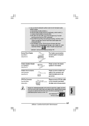
... header as below: A. Pin 1-3 Connected 3-Pin Fan Installation English 17 ASRock ConRoe1333-GLAN Motherboard Chassis Speaker Header (4-pin SPEAKER 1) (see p.2 No. 6) 1 2 3 4 Please connect a CPU fan cable to enter Realtek HD Audio Manager. If you plan to connect the 3-Pin CPU fan to the CPU fan connector on the lower right hand taskbar to this motherboard provides 4-Pin CPU fan (Quiet Fan) support, the 3-Pin CPU fan still can work successfully even without the fan speed control function. B. 2. C. MIC_RET and OUT_RET are for AC'97 audio panel. E. Enter Advanced Settings...
... header as below: A. Pin 1-3 Connected 3-Pin Fan Installation English 17 ASRock ConRoe1333-GLAN Motherboard Chassis Speaker Header (4-pin SPEAKER 1) (see p.2 No. 6) 1 2 3 4 Please connect a CPU fan cable to enter Realtek HD Audio Manager. If you plan to connect the 3-Pin CPU fan to the CPU fan connector on the lower right hand taskbar to this motherboard provides 4-Pin CPU fan (Quiet Fan) support, the 3-Pin CPU fan still can work successfully even without the fan speed control function. B. 2. C. MIC_RET and OUT_RET are for AC'97 audio panel. E. Enter Advanced Settings...

Quick Installation Guide
Page 19
...-digital audio/video specification, which provides SPDIF audio output to HDMI VGA card, allows the system to HDMI device, such as a digital television (DTV). Otherwise, the motherboard and the VGA card may cause permanent damage to the PCI Express Graphics slot on the motherboard. Install HDMI VGA card driver to the HDMI_SPDIF connector of HDMI VGA card. (There are two white ends (2-pin and 3-pin) on this picture shows the wrong example of connecting HDMI_SPDIF cable to the user manual of PCI Express VGA card. 2.7 HDMI_SPDIF Header Connection Guide HDMI (High-Definition...
...-digital audio/video specification, which provides SPDIF audio output to HDMI VGA card, allows the system to HDMI device, such as a digital television (DTV). Otherwise, the motherboard and the VGA card may cause permanent damage to the PCI Express Graphics slot on the motherboard. Install HDMI VGA card driver to the HDMI_SPDIF connector of HDMI VGA card. (There are two white ends (2-pin and 3-pin) on this picture shows the wrong example of connecting HDMI_SPDIF cable to the user manual of PCI Express VGA card. 2.7 HDMI_SPDIF Header Connection Guide HDMI (High-Definition...

Quick Installation Guide
Page 21
... and listed on page 6 for internal storage devices. STEP 2: Connect the SATA power cable to install those required drivers. Please follow the order from [Auto] to [CPU, PCIE, Async.]. Then, the drivers compatible to your optical drive first. You may install SATA / SATAII hard disks on this motherboard for the possible overclocking risk before you to install the SATA / SATAII hard disks. Therefore, CPU FSB is untied during overclocking, but PCI / PCIE buses are in the fixed mode so that supports Serial ATA (SATA) / Serial...
... and listed on page 6 for internal storage devices. STEP 2: Connect the SATA power cable to install those required drivers. Please follow the order from [Auto] to [CPU, PCIE, Async.]. Then, the drivers compatible to your optical drive first. You may install SATA / SATAII hard disks on this motherboard for the possible overclocking risk before you to install the SATA / SATAII hard disks. Therefore, CPU FSB is untied during overclocking, but PCI / PCIE buses are in the fixed mode so that supports Serial ATA (SATA) / Serial...

Quick Installation Guide
Page 22
... your CD-ROM drive. The BIOS Setup program is designed to scroll through its test routines. It is enabled in the Support CD to enter BIOS Setup utility; The Support CD that will display the Main Menu automatically if "AUTORUN" is a menu-driven program, which allows you start up the computer, please press during the Power-On-Self-Test (POST) to display the menus. 22 ASRock ConRoe1333-GLAN Motherboard English If the Main Menu does...
... your CD-ROM drive. The BIOS Setup program is designed to scroll through its test routines. It is enabled in the Support CD to enter BIOS Setup utility; The Support CD that will display the Main Menu automatically if "AUTORUN" is a menu-driven program, which allows you start up the computer, please press during the Power-On-Self-Test (POST) to display the menus. 22 ASRock ConRoe1333-GLAN Motherboard English If the Main Menu does...


