
User Manual
Page 5
Chapter 3 and 4 contains the configuration guide to AHCI mode. 5 ASRock website http://www.asrock.com If you are using. www.asrock.com/support/index.asp 1.1 Package Contents ASRock C216 WS Motherboard (ATX Form Factor: 12.0-in x 9.6-in Storage Configuration to BIOS setup and information of the Support CD. To get better performance in Windows® 8 / 8 64-bit / 7 / 7 ...
Chapter 3 and 4 contains the configuration guide to AHCI mode. 5 ASRock website http://www.asrock.com If you are using. www.asrock.com/support/index.asp 1.1 Package Contents ASRock C216 WS Motherboard (ATX Form Factor: 12.0-in x 9.6-in Storage Configuration to BIOS setup and information of the Support CD. To get better performance in Windows® 8 / 8 64-bit / 7 / 7 ...

User Manual
Page 6
... Supports Intel® HD Graphics Built-in Visuals and the VGA outputs can be supported only with Intel® Ivy Bridge CPU - Intel® C216 - Intel® Socket 1155 for 3rd/2nd Generation CoreTM i7/CoreTM i5/ CoreTM i3 Processors - Supports Intel® Turbo Boost 2.0 Technology - ...Graphics - Supports DDR3 1600/1333/1066 ECC/non-ECC, un-buffered memory * ECC memory is only supported with Intel® Sandy Bridge CPU 6 ATX Form Factor: 12.0-in x 9.6-in Visuals: Intel® Quick Sync Video, Intel® InTruTM 3D, Intel® Clear Video HD Technology, Intel...
... Supports Intel® HD Graphics Built-in Visuals and the VGA outputs can be supported only with Intel® Ivy Bridge CPU - Intel® C216 - Intel® Socket 1155 for 3rd/2nd Generation CoreTM i7/CoreTM i5/ CoreTM i3 Processors - Supports Intel® Turbo Boost 2.0 Technology - ...Graphics - Supports DDR3 1600/1333/1066 ECC/non-ECC, un-buffered memory * ECC memory is only supported with Intel® Sandy Bridge CPU 6 ATX Form Factor: 12.0-in x 9.6-in Visuals: Intel® Quick Sync Video, Intel® InTruTM 3D, Intel® Clear Video HD Technology, Intel...
User Manual
Page 8
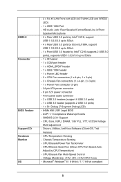
... +5V, +3.3V, CPU Vcore - CPU Core, IGPU, DRAM, 1.8V PLL, VTT, VCCSA Voltage Multi-adjustment - SMBIOS 2.3.1 Support - Adjust by Intel® C216 (supports 2 USB 3.0 ports), supports USB 1.1/2.0/3.0 up to 5Gb/s - 1 x IR header - 1 x COM port header - 1 x HDMI_SPDIF header - 1... Fan connectors (1 x 4-pin, 1 x 3-pin) - 3 x Chassis Fan connectors (1 x 4-pin, 2 x 3-pin) - 1 x Power Fan connector (3-pin) - 24 pin ATX power connector - 8 pin 12V power connector - Chassis Temperature Sensing - Microsoft® Windows® 8 / 8 64-bit / 7 / 7 64-bit compliant 8 CPU Temperature Sensing -...
... +5V, +3.3V, CPU Vcore - CPU Core, IGPU, DRAM, 1.8V PLL, VTT, VCCSA Voltage Multi-adjustment - SMBIOS 2.3.1 Support - Adjust by Intel® C216 (supports 2 USB 3.0 ports), supports USB 1.1/2.0/3.0 up to 5Gb/s - 1 x IR header - 1 x COM port header - 1 x HDMI_SPDIF header - 1... Fan connectors (1 x 4-pin, 1 x 3-pin) - 3 x Chassis Fan connectors (1 x 4-pin, 2 x 3-pin) - 1 x Power Fan connector (3-pin) - 24 pin ATX power connector - 8 pin 12V power connector - Chassis Temperature Sensing - Microsoft® Windows® 8 / 8 64-bit / 7 / 7 64-bit compliant 8 CPU Temperature Sensing -...

User Manual
Page 11
...34 AUDIO CODEC PCIE2 33 PCI1 PCIE3 CMOS Battery 32 Super I/O 31 PCIE4 8 USB3_6_7 9 10 11 Intel 12 C216 13 14 30 29 28 RoHS HD_AUDIO1 1 HDMI_SPDIF1 COM1 1 1 PCI2 C216 WS PCIE5 IR1 1 FRONT_1394 1 CLRCMOS1 1 CHA_FAN1 USB8_9 1 USB6_7 1 Dr. Debug 64Mb BIOS SPEAKER1 1 PLED1 1 ...PLED PWRBTN CHA_FAN3 1 HDLED RESET PANEL1 15 27 26 25 24 23 22 21 20 19 18 17 16 1 1155-Pin CPU Socket 2 ATX 12V Power Connector (ATX12V1...
...34 AUDIO CODEC PCIE2 33 PCI1 PCIE3 CMOS Battery 32 Super I/O 31 PCIE4 8 USB3_6_7 9 10 11 Intel 12 C216 13 14 30 29 28 RoHS HD_AUDIO1 1 HDMI_SPDIF1 COM1 1 1 PCI2 C216 WS PCIE5 IR1 1 FRONT_1394 1 CLRCMOS1 1 CHA_FAN1 USB8_9 1 USB6_7 1 Dr. Debug 64Mb BIOS SPEAKER1 1 PLED1 1 ...PLED PWRBTN CHA_FAN3 1 HDLED RESET PANEL1 15 27 26 25 24 23 22 21 20 19 18 17 16 1 1155-Pin CPU Socket 2 ATX 12V Power Connector (ATX12V1...
User Manual
Page 15
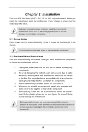
... the power cord from the power supply. static pad or in the bag that the power is switched off or the power cord is an ATX form factor (12.0" x 9.6", 30.5 x 24.4 cm) motherboard. Failure to do not touch the ICs. 4. Also remember to unplug the power cord before you handle the...
... the power cord from the power supply. static pad or in the bag that the power is switched off or the power cord is an ATX form factor (12.0" x 9.6", 30.5 x 24.4 cm) motherboard. Failure to do not touch the ICs. 4. Also remember to unplug the power cord before you handle the...
User Manual
Page 35
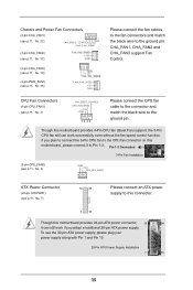
... Fan Control. Pin 1-3 Connected 3-Pin Fan Installation (3-pin CPU_FAN2) (see p.11, No. 4) GND +12V CPU_FAN_SPEED ATX Power Connector (24-pin ATXPWR1) (see p.11, No. 7) 12 24 Please connect an ATX power supply to the ground pin. CPU Fan Connectors (4-pin CPU_FAN1) (see p.11, No. 3) FAN_SPEED_CONTROL CPU_FAN_SPEED +12V...connect the CPU fan cable to the connector and match the black wire to this connector. 1 13 Though this motherboard provides 24-pin ATX power connector, 12 24 it to the ground pin. If you plan to connect the 3-Pin CPU fan to the CPU fan connector...
... Fan Control. Pin 1-3 Connected 3-Pin Fan Installation (3-pin CPU_FAN2) (see p.11, No. 4) GND +12V CPU_FAN_SPEED ATX Power Connector (24-pin ATXPWR1) (see p.11, No. 7) 12 24 Please connect an ATX power supply to the ground pin. CPU Fan Connectors (4-pin CPU_FAN1) (see p.11, No. 3) FAN_SPEED_CONTROL CPU_FAN_SPEED +12V...connect the CPU fan cable to the connector and match the black wire to this connector. 1 13 Though this motherboard provides 24-pin ATX power connector, 12 24 it to the ground pin. If you plan to connect the 3-Pin CPU fan to the CPU fan connector...
User Manual
Page 36
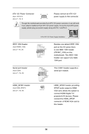
...HDMI_SPDIF1) (see p.11, No. 26) This COM1 header supports a serial port module. ATX 12V Power Connector 8 5 (8-pin ATX12V1) (see p.11, No. 2) 4 1 Please connect an ATX 12V power supply to this motherboard. To use the 4-pin ATX power supply, please plug your power supply along with Pin 1 and Pin 5. 8 ...5 IEEE 1394 Header (9-pin FRONT_1394) (see p.11 No. 24) 4-Pin ATX 12V Power Supply Installation 4 1 RXTPAM_0 GND RXTPBM_0 +12V GND 1 +12V RXTPBP_0 GND RXTPAP_0 Besides one default IEEE 1394 port on this connector. ...
...HDMI_SPDIF1) (see p.11, No. 26) This COM1 header supports a serial port module. ATX 12V Power Connector 8 5 (8-pin ATX12V1) (see p.11, No. 2) 4 1 Please connect an ATX 12V power supply to this motherboard. To use the 4-pin ATX power supply, please plug your power supply along with Pin 1 and Pin 5. 8 ...5 IEEE 1394 Header (9-pin FRONT_1394) (see p.11 No. 24) 4-Pin ATX 12V Power Supply Installation 4 1 RXTPAM_0 GND RXTPBM_0 +12V GND 1 +12V RXTPBP_0 GND RXTPAP_0 Besides one default IEEE 1394 port on this connector. ...