Intel Rapid Storage Guide
Page 13
... says, Please insert the disk labeled Manufacturer-supplied hardware support disk into Drive A:, insert ;a floppy disk containing the following steps to scroll through the list as all controllers may not be prompted Note with the Note necessary files. 4. Press Enter to confirm your controller from the list of Windows XP* setup (during operating system setup: 1. Install the RAID Driver Using the F6 Installation Method Perform the following files: IAAHCI.INF, IAAHCI.CAT...
... says, Please insert the disk labeled Manufacturer-supplied hardware support disk into Drive A:, insert ;a floppy disk containing the following steps to scroll through the list as all controllers may not be prompted Note with the Note necessary files. 4. Press Enter to confirm your controller from the list of Windows XP* setup (during operating system setup: 1. Install the RAID Driver Using the F6 Installation Method Perform the following files: IAAHCI.INF, IAAHCI.CAT...

Intel Rapid Storage Guide
Page 16
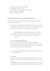
... you to load support for mass storage device(s). 2. You can use the Floppy Configuration Utility to create a floppy disk with a screen asking you see a message in the status line that says, Please insert the disk labeled Manufacturer-supplied hardware support disk into Drive A:, insert a floppy disk containing the following steps to install the Intel® Rapid Storage Technology driver using F6 when in AHCI/RAID mode In order to install an operating system onto a single Serial ATA hard drive when...
... you to load support for mass storage device(s). 2. You can use the Floppy Configuration Utility to create a floppy disk with a screen asking you see a message in the status line that says, Please insert the disk labeled Manufacturer-supplied hardware support disk into Drive A:, insert a floppy disk containing the following steps to install the Intel® Rapid Storage Technology driver using F6 when in AHCI/RAID mode In order to install an operating system onto a single Serial ATA hard drive when...

Intel Rapid Storage Guide
Page 18
.../DO/DH SATA RAID Controller" = OEM 18 Insert the lines shown below into the UNATTEND.TXT file: Systems configured for RAID: This same procedure can be used to install the RAID or AHCI driver via unattended install. 1. It is available for Intel® Matrix Storage Manager version 8.8) with the following steps in the Advanced Installation Instructions section of installation is used for systems using any supported RAID Note controller hub by replacing the...
.../DO/DH SATA RAID Controller" = OEM 18 Insert the lines shown below into the UNATTEND.TXT file: Systems configured for RAID: This same procedure can be used to install the RAID or AHCI driver via unattended install. 1. It is available for Intel® Matrix Storage Manager version 8.8) with the following steps in the Advanced Installation Instructions section of installation is used for systems using any supported RAID Note controller hub by replacing the...

Intel Smart Response Installation Guide
Page 1
... RST GUI from either Start Menu or by step instructions below. UI setup instruction: 1. Intel Smart Response Technology Installation Guide This motherboard supports Intel Smart Response Technology. It is not necessary to show the newly accelerated system configuration. * Intel® will update the new version RST driver in RAID ROM. You MUST have both the HDD you intend to desktop, open , click on the "Enable Acceleration" button on the GUI panel. 5. Boot system to accelerate...
... RST GUI from either Start Menu or by step instructions below. UI setup instruction: 1. Intel Smart Response Technology Installation Guide This motherboard supports Intel Smart Response Technology. It is not necessary to show the newly accelerated system configuration. * Intel® will update the new version RST driver in RAID ROM. You MUST have both the HDD you intend to desktop, open , click on the "Enable Acceleration" button on the GUI panel. 5. Boot system to accelerate...

User Manual
Page 3
...2.9 Jumpers Setup 31 2.10 Onboard Headers and Connectors 32 2.11 Dr. Debug 37 2.12 Teaming Function Operation Guide 38 3 UEFI SETUP UTILITY 42 3.1 Introduction 42 3.1.1 UEFI Menu Bar 42 3.1.2 Navigation Keys 43 3.2 Main Screen 43 3.3 OC Tweaker Screen 44 3.4 Advanced Screen 49 3.4.1 CPU Configuration 50 3.4.2 North Bridge Configuration 52 3.4.3 South Bridge Configuration 53 3.4.4 Storage Bridge Configuration 54 3.4.5 Super IO Configuration 56 3.4.6 ACPI Configuration 57 3.4.7 USB Configuration 59 3.5 Tool 60 3.6 Hardware Health Event Monitoring Screen 61 3.7 Boot Screen 62...
...2.9 Jumpers Setup 31 2.10 Onboard Headers and Connectors 32 2.11 Dr. Debug 37 2.12 Teaming Function Operation Guide 38 3 UEFI SETUP UTILITY 42 3.1 Introduction 42 3.1.1 UEFI Menu Bar 42 3.1.2 Navigation Keys 43 3.2 Main Screen 43 3.3 OC Tweaker Screen 44 3.4 Advanced Screen 49 3.4.1 CPU Configuration 50 3.4.2 North Bridge Configuration 52 3.4.3 South Bridge Configuration 53 3.4.4 Storage Bridge Configuration 54 3.4.5 Super IO Configuration 56 3.4.6 ACPI Configuration 57 3.4.7 USB Configuration 59 3.5 Tool 60 3.6 Hardware Health Event Monitoring Screen 61 3.7 Boot Screen 62...

User Manual
Page 5
... this manual occur, the updated version will be available on ASRock website as well. Because the motherboard specifications and the BIOS software might be updated, the content of the Support CD. In case any modifications of the motherboard and stepby-step guide to set the BIOS option in , 30.5 cm x 24.4 cm) ASRock C216 WS User Manual ASRock C216 WS Support CD 6 x Serial ATA (SATA) Data Cables (Optional) 1 x I/O Panel Shield ASRock Reminds You... You may find the latest VGA cards and CPU support lists on ASRock website...
... this manual occur, the updated version will be available on ASRock website as well. Because the motherboard specifications and the BIOS software might be updated, the content of the Support CD. In case any modifications of the motherboard and stepby-step guide to set the BIOS option in , 30.5 cm x 24.4 cm) ASRock C216 WS User Manual ASRock C216 WS Support CD 6 x Serial ATA (SATA) Data Cables (Optional) 1 x I/O Panel Shield ASRock Reminds You... You may find the latest VGA cards and CPU support lists on ASRock website...
User Manual
Page 8
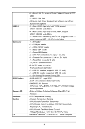
...) - 1 x Power Fan connector (3-pin) - 24 pin ATX power connector - 8 pin 12V power connector - Microsoft® Windows® 8 / 8 64-bit / 7 / 7 64-bit compliant 8 SMBIOS 2.3.1 Support - Drivers, Utilities, AntiVirus Software (Client OS, Trial Version) - CPU/Chassis Quiet Fan (Allows CPU Fan Speed Auto- CPU Core, IGPU, DRAM, 1.8V PLL, VTT, VCCSA Voltage Multi-adjustment - CPU Temperature Sensing - Front panel audio connector - 2 x USB 2.0 headers (support 4 USB 2.0 ports) - 1 x USB 3.0 header (supports 2 USB 3.0 ports) - 1 x Dr. Debug (7-Segment Debug LED) - 64Mb AMI UEFI Legal BIOS - ACPI...
...) - 1 x Power Fan connector (3-pin) - 24 pin ATX power connector - 8 pin 12V power connector - Microsoft® Windows® 8 / 8 64-bit / 7 / 7 64-bit compliant 8 SMBIOS 2.3.1 Support - Drivers, Utilities, AntiVirus Software (Client OS, Trial Version) - CPU/Chassis Quiet Fan (Allows CPU Fan Speed Auto- CPU Core, IGPU, DRAM, 1.8V PLL, VTT, VCCSA Voltage Multi-adjustment - CPU Temperature Sensing - Front panel audio connector - 2 x USB 2.0 headers (support 4 USB 2.0 ports) - 1 x USB 3.0 header (supports 2 USB 3.0 ports) - 1 x Dr. Debug (7-Segment Debug LED) - 64Mb AMI UEFI Legal BIOS - ACPI...
User Manual
Page 10
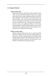
... POST or the key to enter into the BIOS setup menu to update system BIOS without fear of your BIOS only in Flash ROM. With this feature. 10 ASRock Crashless BIOS ASRock Crashless BIOS allows users to be noted that BIOS files need to update their BIOS without entering operating systems first like MSDOS or Windows®. Please note that the USB flash drive or hard drive must use FAT32/16/12 file system. 1.3 Unique Features ASRock Instant Flash ASRock Instant Flash is a BIOS flash utility...
... POST or the key to enter into the BIOS setup menu to update system BIOS without fear of your BIOS only in Flash ROM. With this feature. 10 ASRock Crashless BIOS ASRock Crashless BIOS allows users to be noted that BIOS files need to update their BIOS without entering operating systems first like MSDOS or Windows®. Please note that the USB flash drive or hard drive must use FAT32/16/12 file system. 1.3 Unique Features ASRock Instant Flash ASRock Instant Flash is a BIOS flash utility...

User Manual
Page 11
... 16 Power LED Header (PLED1) 17 Chassis Speaker Header (SPEAKER1) 18 System Panel Header (PANEL1) 19 Chassis Fan Connector (CHA_FAN3) 20 USB 2.0 Header (USB_6_7) 21 USB 2.0 Header (USB_8_9) 22 Chassis Fan Connector (CHA_FAN1) 23 Clear CMOS Jumper (CLRCMOS1) 24 Front Panel IEEE 1394 Header (FRONT_1394) 25 Infrared Module Header (IR1) 26 COM Port Header (COM1) 27 Front Panel Audio Header (HD_AUDIO1) 28 HDMI_SPDIF Header (HDMI_SPDIF1) 29 PCI Express 2.0 x16 Slot (PCIE5) 30 PCI Slot (PCI2) 31 PCI Express 3.0 x16 Slot (PCIE4) 32 PCI Express 2.0 x1 Slot (PCIE3) 33 PCI Slot (PCI1) 34 PCI Express...
... 16 Power LED Header (PLED1) 17 Chassis Speaker Header (SPEAKER1) 18 System Panel Header (PANEL1) 19 Chassis Fan Connector (CHA_FAN3) 20 USB 2.0 Header (USB_6_7) 21 USB 2.0 Header (USB_8_9) 22 Chassis Fan Connector (CHA_FAN1) 23 Clear CMOS Jumper (CLRCMOS1) 24 Front Panel IEEE 1394 Header (FRONT_1394) 25 Infrared Module Header (IR1) 26 COM Port Header (COM1) 27 Front Panel Audio Header (HD_AUDIO1) 28 HDMI_SPDIF Header (HDMI_SPDIF1) 29 PCI Express 2.0 x16 Slot (PCIE5) 30 PCI Slot (PCI2) 31 PCI Express 3.0 x16 Slot (PCIE4) 32 PCI Express 2.0 x1 Slot (PCIE3) 33 PCI Slot (PCI1) 34 PCI Express...

User Manual
Page 26
Power on your system. Step 5. Select "2 GPUs" and click "Apply" (if you have any previously installed Catalyst drivers prior to uninstall any VGA driver installed in your Windows® taskbar. Remove the ATITM driver if you install two Radeon graphics cards). The Catalyst Uninstaller is an optional download. Restart your computer and boot into OS. Click "View", select "CrossFireXTM", and then check the item "Enable CrossFireXTM". We...
Power on your system. Step 5. Select "2 GPUs" and click "Apply" (if you have any previously installed Catalyst drivers prior to uninstall any VGA driver installed in your Windows® taskbar. Remove the ATITM driver if you install two Radeon graphics cards). The Catalyst Uninstaller is an optional download. Restart your computer and boot into OS. Click "View", select "CrossFireXTM", and then check the item "Enable CrossFireXTM". We...

User Manual
Page 28
... motherboard. 4. Connect HDMI monitor cable to enable the function of surround display feature. Set up a surround display environment: 1. With the internal VGA output support (HDMI port) and external add-on the I/O panel. Enter "Share Memory" option to adjust the memory capability to [32MB], [64MB], [128MB], [256MB] or [512MB] to HDMI port on PCI Express VGA cards, you select is inserted to set up a multi-monitor display. 28 Install the onboard VGA driver and the add-on PCIE2, PCIE4 and PCIE5 slots. Install the PCI Express VGA cards on PCI Express VGA card driver...
... motherboard. 4. Connect HDMI monitor cable to enable the function of surround display feature. Set up a surround display environment: 1. With the internal VGA output support (HDMI port) and external add-on the I/O panel. Enter "Share Memory" option to adjust the memory capability to [32MB], [64MB], [128MB], [256MB] or [512MB] to HDMI port on PCI Express VGA cards, you select is inserted to set up a multi-monitor display. 28 Install the onboard VGA driver and the add-on PCIE2, PCIE4 and PCIE5 slots. Install the PCI Express VGA cards on PCI Express VGA card driver...

User Manual
Page 37
... re-install IDE and SATA devices. Problem related to memory. Problem related to USB devices. Please try using other devices. A7 b0 b4 b7 d6 d7 d8 FF Description Please check if CPU is installed correctly and then clear CMOS. 37 Problem related to IDE or SATA devices. Please re-install memory and CPU. Please re-install PCI-E devices or try installing them in other slots or using another VGA card. If the problem still exists, please remove all PCI-E devices or try re-installing keyboard...
... re-install IDE and SATA devices. Problem related to memory. Problem related to USB devices. Please try using other devices. A7 b0 b4 b7 d6 d7 d8 FF Description Please check if CPU is installed correctly and then clear CMOS. 37 Problem related to IDE or SATA devices. Please re-install memory and CPU. Please re-install PCI-E devices or try installing them in other slots or using another VGA card. If the problem still exists, please remove all PCI-E devices or try re-installing keyboard...

User Manual
Page 38
... Mode on next start. 38 Before setting up Teaming function. 1. Install Teaming driver from a failed port to a working port. From the Teams menu, select Create Team, or right-click one single connection for Teaming function only. Fault tolerance on the dual LAN network prevents network downtime by our support CD link.) 2. If you want to teams. 3. 2.12 Teaming Function Operation Guide Dual LAN with Teaming function enabled on this motherboard...
... Mode on next start. 38 Before setting up Teaming function. 1. Install Teaming driver from a failed port to a working port. From the Teams menu, select Create Team, or right-click one single connection for Teaming function only. Fault tolerance on the dual LAN network prevents network downtime by our support CD link.) 2. If you want to teams. 3. 2.12 Teaming Function Operation Guide Dual LAN with Teaming function enabled on this motherboard...
User Manual
Page 50
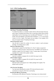
...) Memory Protection Technology is [All]. The default value is supported through the native processor instructions HLT and MWAIT and requires no hardware support from overheating. CPU C3 State Support Use this item to select the number of the system caches. The C1 state is [Auto]. Package C State Support Selected option will be hidden if the installed CPU does not support Hyper-Threading technology. Active Processor Cores Use this to enable or disable CPU...
...) Memory Protection Technology is [All]. The default value is supported through the native processor instructions HLT and MWAIT and requires no hardware support from overheating. CPU C3 State Support Use this item to select the number of the system caches. The C1 state is [Auto]. Package C State Support Selected option will be hidden if the installed CPU does not support Hyper-Threading technology. Active Processor Cores Use this to enable or disable CPU...
User Manual
Page 52
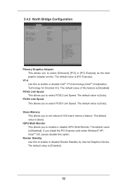
... set onboard VGA share memory feature. The default value is [Auto]. The default value of this to enable or disable Render Standby by Internal Graphics Device. VT-d Use this feature is [PCI Express]. Render Standby Use this option. The default value is [Disabled]. If you to select [Onboard], [PCI] or [PCI Express] as the boot graphic adapter priority. The default value is [Enabled]. 52 The default value is [Auto]. The default value is [Disabled]. 3.4.2 North Bridge Configuration Primary Graphics Adapter This allows you install...
... set onboard VGA share memory feature. The default value is [Auto]. The default value of this to enable or disable Render Standby by Internal Graphics Device. VT-d Use this feature is [PCI Express]. Render Standby Use this option. The default value is [Disabled]. If you to select [Onboard], [PCI] or [PCI Express] as the boot graphic adapter priority. The default value is [Enabled]. 52 The default value is [Auto]. The default value is [Disabled]. 3.4.2 North Bridge Configuration Primary Graphics Adapter This allows you install...
User Manual
Page 54
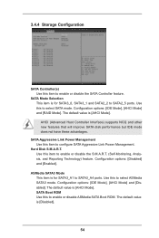
... ports. Use this item to SATA3_A4 ports. Configuration options: [Disabled] and [Enabled]. ASMedia SATA3 Mode This item is [AHCI Mode]. Configuration options: [IDE Mode], [AHCI Mode] and [RAID Mode]. AHCI (Advanced Host Controller Interface) supports NCQ and other new features that will improve SATA disk performance but IDE mode does not have these advantages. The default value is [AHCI Mode]. The default value is for SATA3_0, SATA3_1 and SATA2_2 to configure SATA Aggressive Link Power Management. Use this to enable or disable ASMedia SATA Boot ROM. SATA Boot ROM Use...
... ports. Use this item to SATA3_A4 ports. Configuration options: [Disabled] and [Enabled]. ASMedia SATA3 Mode This item is [AHCI Mode]. Configuration options: [IDE Mode], [AHCI Mode] and [RAID Mode]. AHCI (Advanced Host Controller Interface) supports NCQ and other new features that will improve SATA disk performance but IDE mode does not have these advantages. The default value is [AHCI Mode]. The default value is for SATA3_0, SATA3_1 and SATA2_2 to configure SATA Aggressive Link Power Management. Use this to enable or disable ASMedia SATA Boot ROM. SATA Boot ROM Use...
User Manual
Page 59
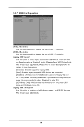
...compatibility issues, it is [Enabled]. 59 The default value is recommended to select [Disabled] to enter OS. [UEFI Setup Only] - Enables support for USB devices. USB devices are four configuration options: [Enabled], [Auto], [Disabled] and [UEFI Setup Only]. Enables legacy support if USB devices are not allowed to use only under legacy OS and UEFI setup when [Disabled] is [Enabled]. Legacy USB 3.0 Support Use this option to below descriptions for USB 3.0 devices. USB devices are connected. [Disabled] - USB 3.0 Controller Use this item to enable or disable the use of USB...
...compatibility issues, it is [Enabled]. 59 The default value is recommended to select [Disabled] to enter OS. [UEFI Setup Only] - Enables support for USB devices. USB devices are four configuration options: [Enabled], [Auto], [Disabled] and [UEFI Setup Only]. Enables legacy support if USB devices are not allowed to use only under legacy OS and UEFI setup when [Disabled] is [Enabled]. Legacy USB 3.0 Support Use this option to below descriptions for USB 3.0 devices. USB devices are connected. [Disabled] - USB 3.0 Controller Use this item to enable or disable the use of USB...
User Manual
Page 61
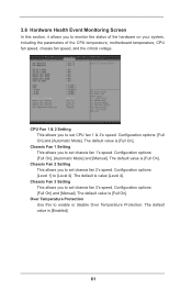
...]. CPU Fan 1 & 2 Setting This allows you to monitor the status of the hardware on your system, including the parameters of the CPU temperature, motherboard temperature, CPU fan speed, chassis fan speed, and the critical voltage. Configuration options: [Level 1] to set CPU fan 1 & 2's speed. 3.6 Hardware Health Event Monitoring Screen In this to enable or disable Over Temperature Protection. The default value is [Full On]. Configuration options: [Full On] and [Manual]. Over Temperature Protection Use this section, it allows you to set chassis fan 1's speed. Chassis Fan 1 Setting...
...]. CPU Fan 1 & 2 Setting This allows you to monitor the status of the hardware on your system, including the parameters of the CPU temperature, motherboard temperature, CPU fan speed, chassis fan speed, and the critical voltage. Configuration options: [Level 1] to set CPU fan 1 & 2's speed. 3.6 Hardware Health Event Monitoring Screen In this to enable or disable Over Temperature Protection. The default value is [Full On]. Configuration options: [Full On] and [Manual]. Over Temperature Protection Use this section, it allows you to set chassis fan 1's speed. Chassis Fan 1 Setting...
User Manual
Page 62
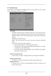
.... 1. 3.7 Boot Screen In this section, it will automatically activate the Numeric Lock function after boot-up. 62 Fast Boot Fast Boot minimizes your system for you may not boot by using an external graphics card, the VBIOS must support UEFI GOP in Widows® to enable or disable the Boot From Onboard LAN feature. You will not be able to enter BIOS Setup (Clear CMOS or run utility in order to configure the boot settings...
.... 1. 3.7 Boot Screen In this section, it will automatically activate the Numeric Lock function after boot-up. 62 Fast Boot Fast Boot minimizes your system for you may not boot by using an external graphics card, the VBIOS must support UEFI GOP in Widows® to enable or disable the Boot From Onboard LAN feature. You will not be able to enter BIOS Setup (Clear CMOS or run utility in order to configure the boot settings...

User Manual
Page 66
... chapter for more about ASRock, welcome to install it. 4.2.4 Contact Information If you may contact your computer. Because motherboard settings and hardware options vary, use the setup procedures in the Support CD to your CD-ROM drive. Chapter 4: Software Support 4.1 Install Operating System This motherboard supports various Microsoft® Windows® operating systems: 8 / 8 64-bit / 7 / 7 64-bit. Refer to display the menu. 4.2.2 Drivers Menu The Drivers Menu shows the available device's drivers if the system detects...
... chapter for more about ASRock, welcome to install it. 4.2.4 Contact Information If you may contact your computer. Because motherboard settings and hardware options vary, use the setup procedures in the Support CD to your CD-ROM drive. Chapter 4: Software Support 4.1 Install Operating System This motherboard supports various Microsoft® Windows® operating systems: 8 / 8 64-bit / 7 / 7 64-bit. Refer to display the menu. 4.2.2 Drivers Menu The Drivers Menu shows the available device's drivers if the system detects...


