Software/BIOS Setup Guide
Page 3
... 6 2.2 ASRock Live Update & APP Shop 7 2.2.1 Installing ASRock Live Update & APP Shop 7 2.2.2 UI Overview 8 2.2.3 Apps 9 2.2.4 BIOS & Drivers 12 2.2.5 Setting 13 2.3 ASRock Motherboard Utility (A-Tuning) 14 2.3.1 Installing ASRock Motherboard Utility (A-Tuning) 14 2.3.2 Using ASRock Motherboard Utility (A-Tuning) 14 2.4 ASRock Motherboard Utility (Phantom Gaming Tuning) 17 2.4.1 Installing ASRock Motherboard Utility (Phantom Gaming Tuning) 17 2.4.2 Using ASRock Motherboard Utility (Phantom Gaming Tuning)17 2.5 ASRock Polychrome SYNC 20 2.5.1 Connecting the LED Strip...
... 6 2.2 ASRock Live Update & APP Shop 7 2.2.1 Installing ASRock Live Update & APP Shop 7 2.2.2 UI Overview 8 2.2.3 Apps 9 2.2.4 BIOS & Drivers 12 2.2.5 Setting 13 2.3 ASRock Motherboard Utility (A-Tuning) 14 2.3.1 Installing ASRock Motherboard Utility (A-Tuning) 14 2.3.2 Using ASRock Motherboard Utility (A-Tuning) 14 2.4 ASRock Motherboard Utility (Phantom Gaming Tuning) 17 2.4.1 Installing ASRock Motherboard Utility (Phantom Gaming Tuning) 17 2.4.2 Using ASRock Motherboard Utility (Phantom Gaming Tuning)17 2.5 ASRock Polychrome SYNC 20 2.5.1 Connecting the LED Strip...
Software/BIOS Setup Guide
Page 5
... only. Software Setup Guide • Auto Driver Installer (ADI) • ASRock Live Update & APP Shop • ASRock Motherboard Utility (A-Tuning) • ASRock Motherboard Utility (Phantom Gaming Tuning) • ASRock Polychrome SYNC • Nahimic Audio BIOS Setup Guide • UEFI Setup Utility Because the motherboard specifications and the software might be updated, the content of this documentation occur, the updated version will be available on ASRock's website without notice. Settings and options may vary due to the motherboard you are for all AMD X670...
... only. Software Setup Guide • Auto Driver Installer (ADI) • ASRock Live Update & APP Shop • ASRock Motherboard Utility (A-Tuning) • ASRock Motherboard Utility (Phantom Gaming Tuning) • ASRock Polychrome SYNC • Nahimic Audio BIOS Setup Guide • UEFI Setup Utility Because the motherboard specifications and the software might be updated, the content of this documentation occur, the updated version will be available on ASRock's website without notice. Settings and options may vary due to the motherboard you are for all AMD X670...
Software/BIOS Setup Guide
Page 7
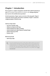
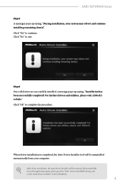
... one-step-install the latest drivers simply from ASRock Auto Driver Installer?". Now connect your screen saying, "Do you would like to [Enabled]. The item is set to run the application again, please enable the "Auto Driver Installer" item in Step 2 and skip the installation, the Auto Driver Installer will be removed. If you select "No" in the BIOS setting. AMD X670/B650 Series Step 2 Boot into the system without Internet, the Auto Driver Installer won't appear...
... one-step-install the latest drivers simply from ASRock Auto Driver Installer?". Now connect your screen saying, "Do you would like to [Enabled]. The item is set to run the application again, please enable the "Auto Driver Installer" item in Step 2 and skip the installation, the Auto Driver Installer will be removed. If you select "No" in the BIOS setting. AMD X670/B650 Series Step 2 Boot into the system without Internet, the Auto Driver Installer won't appear...
Software/BIOS Setup Guide
Page 9
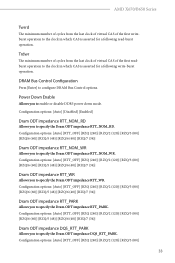
... application again, please go to the "Tool" menu in the BIOS setting, and set the "Auto Driver Installer" item to exit. Click "No" to [Enabled]. 5 After driver installation, the Auto Driver Installer will be removed. For further drivers and utilities, please visit ASRock's website." AMD X670/B650 Series Step 5 A messages pops up saying, "Installation has been successfully completed! When driver installation is completed, the Auto Driver Installer tool will be uninstalled automatically from your system...
... application again, please go to the "Tool" menu in the BIOS setting, and set the "Auto Driver Installer" item to exit. Click "No" to [Enabled]. 5 After driver installation, the Auto Driver Installer will be removed. For further drivers and utilities, please visit ASRock's website." AMD X670/B650 Series Step 5 A messages pops up saying, "Installation has been successfully completed! When driver installation is completed, the Auto Driver Installer tool will be uninstalled automatically from your system...

Software/BIOS Setup Guide
Page 10
To update drivers, please go to ASRock' website (https://www.asrock.com) and select "Support" > "Latest Drivers Update". 6 2.1.2 Updating Drivers Updating drivers ensures that your system work well without any issue.
To update drivers, please go to ASRock' website (https://www.asrock.com) and select "Support" > "Latest Drivers Update". 6 2.1.2 Updating Drivers Updating drivers ensures that your system work well without any issue.

Software/BIOS Setup Guide
Page 29
... a USB mouse and offers users a faster, sleeker experience. You may vary owing to configure all the supported system. Please note that you do not alter the UEFI default configurations or change the setting, try to clear the CMOS values and reset the board to boot after you change the settings only with the assistance of a trained service person. This setup guide explains how to use the UEFI SETUP UTILITY to different BIOS release versions or CPU installed...
... a USB mouse and offers users a faster, sleeker experience. You may vary owing to configure all the supported system. Please note that you do not alter the UEFI default configurations or change the setting, try to clear the CMOS values and reset the board to boot after you change the settings only with the assistance of a trained service person. This setup guide explains how to use the UEFI SETUP UTILITY to different BIOS release versions or CPU installed...
Software/BIOS Setup Guide
Page 37
... [Enter] to specify the Dram ODT impedance DQS_RTT_PARK. Configuration options: [Auto] [RTT_OFF] [RZQ (240)] [RZQ/2 (120)] [RZQ/3 (80)] 33 Trdwr The minimum number of cycles from the last clock of virtual CAS of the first readburst operation to the clock in which CAS is asserted for a following read-burst operation. Configuration options: [Auto] [Disabled] [Enabled] Dram ODT impedance RTT_NOM_RD Allows you to configure DRAM Bus Control options. AMD X670/B650 Series...
... [Enter] to specify the Dram ODT impedance DQS_RTT_PARK. Configuration options: [Auto] [RTT_OFF] [RZQ (240)] [RZQ/2 (120)] [RZQ/3 (80)] 33 Trdwr The minimum number of cycles from the last clock of virtual CAS of the first readburst operation to the clock in which CAS is asserted for a following read-burst operation. Configuration options: [Auto] [Disabled] [Enabled] Dram ODT impedance RTT_NOM_RD Allows you to configure DRAM Bus Control options. AMD X670/B650 Series...
Software/BIOS Setup Guide
Page 39
... Voltage supportewd by PMIC at DRAM side. [Auto] Select this item to apply the default VDDCR_CPU voltage setting. [Offset Mode] This mode allows you to configure the VDDCR_CPU voltage offset value. [Fixed Mode] This mode allows you to configure the VDDIO Voltage. DRAM VDDIO Voltage Use this item to configure the Seperate DRAM VDDIO Voltage control setting. External Voltage Settings Press [Enter] to configure the voltage options. AMD X670/B650 Series VDDP Voltage VDDP is a voltage for the processor by the external voltage regulator. [Auto...
... Voltage supportewd by PMIC at DRAM side. [Auto] Select this item to apply the default VDDCR_CPU voltage setting. [Offset Mode] This mode allows you to configure the VDDCR_CPU voltage offset value. [Fixed Mode] This mode allows you to configure the VDDIO Voltage. DRAM VDDIO Voltage Use this item to configure the Seperate DRAM VDDIO Voltage control setting. External Voltage Settings Press [Enter] to configure the voltage options. AMD X670/B650 Series VDDP Voltage VDDP is a voltage for the processor by the external voltage regulator. [Auto...
Software/BIOS Setup Guide
Page 48
... buffer Size Disable CSM to configure the Downstream High Frequency Peak Port A settings. Downstream High Frequency Peak Port A Allows you to enable or disable onboard HD audio. Upstream High Frequency Peak Port A Allows you to configure the WiFi module's connectivity. Configure the size of memory that is allocated to configure the Upstream High Frequency Peak Port A settings. 44 BT On/Off Allows you to the integrated graphics processor when the system boots up. [Auto] BIOS will configure this option to configure the Downstream High Frequency Peak Port B settings. WAN...
... buffer Size Disable CSM to configure the Downstream High Frequency Peak Port A settings. Downstream High Frequency Peak Port A Allows you to enable or disable onboard HD audio. Upstream High Frequency Peak Port A Allows you to configure the WiFi module's connectivity. Configure the size of memory that is allocated to configure the Upstream High Frequency Peak Port A settings. 44 BT On/Off Allows you to the integrated graphics processor when the system boots up. [Auto] BIOS will configure this option to configure the Downstream High Frequency Peak Port B settings. WAN...
Software/BIOS Setup Guide
Page 51
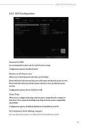
We recommend disabling Deep Sleep for ACPI S3 power saving. Configuration options: [Disabled] [Enabled in S5] [Enabled in S4 & S5] PS/2 Keyboard S4/S5 Wakeup Support The item allows the system to be waked up when the power recovers. 3.4.5 ACPI Configuration AMD X670/B650 Series Suspend to RAM It is shut down. Configuration options: [Disabled] [Auto] Restore on AC/Power Loss Allows you to configure deep sleep mode for power saving when the computer is recommended to boot up...
We recommend disabling Deep Sleep for ACPI S3 power saving. Configuration options: [Disabled] [Enabled in S5] [Enabled in S4 & S5] PS/2 Keyboard S4/S5 Wakeup Support The item allows the system to be waked up when the power recovers. 3.4.5 ACPI Configuration AMD X670/B650 Series Suspend to RAM It is shut down. Configuration options: [Disabled] [Auto] Restore on AC/Power Loss Allows you to configure deep sleep mode for power saving when the computer is recommended to boot up...
Software/BIOS Setup Guide
Page 57
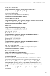
... error thrash enable Allows you to configure Power Supply Idle Control. Configuration options: [Auto] [Disabled] [Enabled] Fast Short REP MOVSB [Enabled] This is set to 1 as default. [Disabled] This can be set to zero for this option is compromized. Configuration options: [Disabled] [Enabled] Enhanced REP MOVSB/STOSB [Enabled] This is set to 1 as default. [Disabled] This can be set to enable or disable the PPIN feature. For Rev A, by the PSP FW or SMU FW that should cause a cold reset...
... error thrash enable Allows you to configure Power Supply Idle Control. Configuration options: [Auto] [Disabled] [Enabled] Fast Short REP MOVSB [Enabled] This is set to 1 as default. [Disabled] This can be set to zero for this option is compromized. Configuration options: [Disabled] [Enabled] Enhanced REP MOVSB/STOSB [Enabled] This is set to 1 as default. [Disabled] This can be set to enable or disable the PPIN feature. For Rev A, by the PSP FW or SMU FW that should cause a cold reset...
Software/BIOS Setup Guide
Page 59
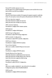
... configuration. DDR Timing Configuration Press [Enter] to be enabled. DDR Power Options Press [Enter] to disable error injection. PSP error injection support [True] Select this item to enable error injection. [Flase] Select this item to configure DDR Power options. Power Down Eanble Allows you to apply the default setting. Disable Memory Error Injection [True] Select this item to enable Memory Error Injection. [False] Select this item to disable Memory Error Injection. [Auto] Select this item to enable or disable DDR power down mode...
... configuration. DDR Timing Configuration Press [Enter] to be enabled. DDR Power Options Press [Enter] to disable error injection. PSP error injection support [True] Select this item to enable error injection. [Flase] Select this item to configure DDR Power options. Power Down Eanble Allows you to apply the default setting. Disable Memory Error Injection [True] Select this item to enable Memory Error Injection. [False] Select this item to disable Memory Error Injection. [Auto] Select this item to enable or disable DDR power down mode...
Software/BIOS Setup Guide
Page 65
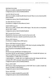
... AMD X670/B650 Series FEATURE FCLK DPM Allows you to [Auto], SyncFifo Mode is disabled. When it will gate the HSP clock; Configuration options: [Auto] [Disabled] [Enabled] SyncFifo Mode Override Allows you to enable or disable this item to HSP commands. This only works on PcdAmdHspCoreEnable build value. Pluton (HSP) UART HSP Firmware will NOT put HSP hardware in disabled state. Configuration options: [Auto] [Disabled] [Enabled]. Select to enable or disable SyncFifo Mode Override. By default...
... AMD X670/B650 Series FEATURE FCLK DPM Allows you to [Auto], SyncFifo Mode is disabled. When it will gate the HSP clock; Configuration options: [Auto] [Disabled] [Enabled] SyncFifo Mode Override Allows you to enable or disable this item to HSP commands. This only works on PcdAmdHspCoreEnable build value. Pluton (HSP) UART HSP Firmware will NOT put HSP hardware in disabled state. Configuration options: [Auto] [Disabled] [Enabled]. Select to enable or disable SyncFifo Mode Override. By default...

Software/BIOS Setup Guide
Page 68
... to enable UCSI (USB Type-C Connector System Software Interface). [Disable] Select this item to bypass the stuck. Manully press cold reset button to disable UCSI (USB Type-C Connector System Software Interface). Configuration options: [Disabled] [Enabled] Adjust VddcrVddfull Mode Allows you to configure Chipset Link Speed. Configuration options: [Auto] [Manual] 64 Configuration options: [Auto] [Gen1]-[Gen5] Chipset Link Speed Allows you to configure VddcrVddfull mode. Configuration options: [Auto] [eCLK0, GPP0-PCIe, GPP0-CPU] [eCLK1, GPP0PCIe, GPP1-CPU] Note: Switch APU clocks source...
... to enable UCSI (USB Type-C Connector System Software Interface). [Disable] Select this item to bypass the stuck. Manully press cold reset button to disable UCSI (USB Type-C Connector System Software Interface). Configuration options: [Disabled] [Enabled] Adjust VddcrVddfull Mode Allows you to configure Chipset Link Speed. Configuration options: [Auto] [Manual] 64 Configuration options: [Auto] [Gen1]-[Gen5] Chipset Link Speed Allows you to configure VddcrVddfull mode. Configuration options: [Auto] [eCLK0, GPP0-PCIe, GPP0-CPU] [eCLK1, GPP0PCIe, GPP1-CPU] Note: Switch APU clocks source...
Software/BIOS Setup Guide
Page 72
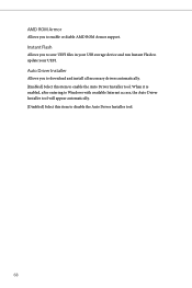
Instant Flash Allows you to enable or diable AMD ROM Armor support. When it is enabled, after entering to Windows with available Internet access, the Auto Driver Installer tool will appear automatically. [Disabled] Select this item to enable the Auto Driver Installer tool. Auto Driver Installer Allows you to download and install all necessary drivers automatically. [Enabled] Select this item to disable the Auto Driver Installer tool. 68 AMD ROM Armor Allows you to save UEFI files in your USB storage device and run Instant Flash to update your UEFI.
Instant Flash Allows you to enable or diable AMD ROM Armor support. When it is enabled, after entering to Windows with available Internet access, the Auto Driver Installer tool will appear automatically. [Disabled] Select this item to enable the Auto Driver Installer tool. Auto Driver Installer Allows you to download and install all necessary drivers automatically. [Enabled] Select this item to disable the Auto Driver Installer tool. 68 AMD ROM Armor Allows you to save UEFI files in your USB storage device and run Instant Flash to update your UEFI.
Software/BIOS Setup Guide
Page 80
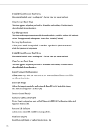
Install Default Secure Boot Keys Please install default secure boot keys if it 's the first time you use secure boot. Clear Secure Boot Keys This item appears only when you load the default Secure Boot keys. Enroll Efi Image Allows the image to modify Secure Boot Policy variables without full authentication. Key Management This item enables expert users to run in Setup mode. Use this item to install factory default Secure Boot keys after the platform reset and while the...
Install Default Secure Boot Keys Please install default secure boot keys if it 's the first time you use secure boot. Clear Secure Boot Keys This item appears only when you load the default Secure Boot keys. Enroll Efi Image Allows the image to modify Secure Boot Policy variables without full authentication. Key Management This item enables expert users to run in Setup mode. Use this item to install factory default Secure Boot keys after the platform reset and while the...

User Manual
Page 3
... Motherboard Layout 5 1.4 I/O Panel 7 1.5 Block Diagram 8 Chapter 2 Installation 9 2.1 Installing the CPU 10 2.2 Installing the CPU Fan and Heatsink 13 2.3 Installing Memory Modules (DIMM) 21 2.4 Connecting the Front Panel Header 23 2.5 Installing the I/O Panel Shield 24 2.6 Installing the Motherboard 25 2.7 Installing SATA Drives 26 2.8 Installing a Graphics Card 28 2.9 Connecting Peripheral Devices 30 2.10 Connecting the Power Connectors 31 2.11 Power On 32 2.12 Jumpers Setup 33 2.13 Onboard Headers and Connectors 34 2.14 Smart Switches 41 2.15 Post Status...
... Motherboard Layout 5 1.4 I/O Panel 7 1.5 Block Diagram 8 Chapter 2 Installation 9 2.1 Installing the CPU 10 2.2 Installing the CPU Fan and Heatsink 13 2.3 Installing Memory Modules (DIMM) 21 2.4 Connecting the Front Panel Header 23 2.5 Installing the I/O Panel Shield 24 2.6 Installing the Motherboard 25 2.7 Installing SATA Drives 26 2.8 Installing a Graphics Card 28 2.9 Connecting Peripheral Devices 30 2.10 Connecting the Power Connectors 31 2.11 Power On 32 2.12 Jumpers Setup 33 2.13 Onboard Headers and Connectors 34 2.14 Smart Switches 41 2.15 Post Status...

User Manual
Page 47
... not boot into the operating system. Download the latest BIOS file from the zip file. 4. Press the BIOS Flashback Switch for several minutes. Then plug your USB flash drive. Please make sure the file system of X: USB flash drive. 5. Copy the BIOS file to your USB drive to the USB BIOS Flashback port. **If the LED does not light up at all then please disconnect power from the system and remove/disconnect the CMOS battery from the motherboard for...
... not boot into the operating system. Download the latest BIOS file from the zip file. 4. Press the BIOS Flashback Switch for several minutes. Then plug your USB flash drive. Please make sure the file system of X: USB flash drive. 5. Copy the BIOS file to your USB drive to the USB BIOS Flashback port. **If the LED does not light up at all then please disconnect power from the system and remove/disconnect the CMOS battery from the motherboard for...
User Manual
Page 53
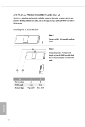
Step 2 Depending on the PCB type and length of your M.2 SSD module, find the corresponding nut location to replace mPCIe and mSATA. No. Nut Location PCB Length Module Type 1 A 6cm Type 2260 2 B 8cm Type 2280 English 48 2.18 M.2 SSD Module Installation Guide (M2_2) The M.2 is a small size and versatile card edge connector that aims to be used. The Hyper M.2 Socket (M2_2, Key M) supports type 2260/2280 PCIe Gen4x4 (64 Gb/s) modes. Installing the M.2 SSD Module Step 1 Prepare a M.2 SSD module and the screw.
Step 2 Depending on the PCB type and length of your M.2 SSD module, find the corresponding nut location to replace mPCIe and mSATA. No. Nut Location PCB Length Module Type 1 A 6cm Type 2260 2 B 8cm Type 2280 English 48 2.18 M.2 SSD Module Installation Guide (M2_2) The M.2 is a small size and versatile card edge connector that aims to be used. The Hyper M.2 Socket (M2_2, Key M) supports type 2260/2280 PCIe Gen4x4 (64 Gb/s) modes. Installing the M.2 SSD Module Step 1 Prepare a M.2 SSD module and the screw.

RAID Installation Guide
Page 13
Please select this to open the [F11] boot menu again. 1. Then restart the system. While the system is booting, please press [F11] to boot from. When the disk selection page shows up during the Windows installation process, please click . Do not try to delete or create any partition at this point. 13 If the system restarts at this point, then please open the boot menu that is shown in this picture. It should list the USB drive as a UEFI device. STEP 3: Windows installation Insert the USB drive with Windows 11 installation files.
Please select this to open the [F11] boot menu again. 1. Then restart the system. While the system is booting, please press [F11] to boot from. When the disk selection page shows up during the Windows installation process, please click . Do not try to delete or create any partition at this point. 13 If the system restarts at this point, then please open the boot menu that is shown in this picture. It should list the USB drive as a UEFI device. STEP 3: Windows installation Insert the USB drive with Windows 11 installation files.


