
RAID Installation Guide
Page 2
... make a SATA driver diskette, press or to enter BIOS setup to set . It will double the data transfer rate of data from one drive fails. 2 RAID 1 (Data Mirroring) RAID 1 is an instruction for "Redundant Array of the data in the other drive if one drive to read and write data in our support CD, then you to RAID mode by using the onboard FastBuild BIOS utility under BIOS environment. 1. AMD BIOS RAID Installation Guide AMD BIOS RAID Installation Guide is...
... make a SATA driver diskette, press or to enter BIOS setup to set . It will double the data transfer rate of data from one drive fails. 2 RAID 1 (Data Mirroring) RAID 1 is an instruction for "Redundant Array of the data in the other drive if one drive to read and write data in our support CD, then you to RAID mode by using the onboard FastBuild BIOS utility under BIOS environment. 1. AMD BIOS RAID Installation Guide AMD BIOS RAID Installation Guide is...

RAID Installation Guide
Page 8
...system boot, press or key to finish the driver copy process. During Windows installation process, when Disk selection page show up, please click . E. B. C. Follow instructions to enter UEFI setup utility. STEP 3.2: Download driver from ASRock's website and unzip the file into your USB flash drive. 8 STEP 4: Windows installation A. B. D. STEP 3.1: Copy RAID driver to a USB flash drive You can choose either STEP 3.1 or STEP 3.2 to Tools Easy RAID Installer F. Go to finish the configuration. Plug a USB drive into the DVD-ROM drive. Please download the "SATA Floppy...
...system boot, press or key to finish the driver copy process. During Windows installation process, when Disk selection page show up, please click . E. B. C. Follow instructions to enter UEFI setup utility. STEP 3.2: Download driver from ASRock's website and unzip the file into your USB flash drive. 8 STEP 4: Windows installation A. B. D. STEP 3.1: Copy RAID driver to a USB flash drive You can choose either STEP 3.1 or STEP 3.2 to Tools Easy RAID Installer F. Go to finish the configuration. Plug a USB drive into the DVD-ROM drive. Please download the "SATA Floppy...

RAID Installation Guide
Page 14
K. A. Plug a USB drive into your USB flash disk. 14 Please download the "SATA Floppy Imaged driver" from ASRock's website A. Please install the DVD-ROM. During system boot, press or key to finish the driver copy process. Insert the Support CD into the DVD-ROM drive. Follow instructions to enter UEFI setup utility. Click to save to finish the configuration. B. STEP 2.2: Download driver from ASRock's website and unzip the file into one of the USB port. STEP 2.1: Copy RAID driver to a USB flash drive You can choose either STEP2.1 or...
K. A. Plug a USB drive into your USB flash disk. 14 Please download the "SATA Floppy Imaged driver" from ASRock's website A. Please install the DVD-ROM. During system boot, press or key to finish the driver copy process. Insert the Support CD into the DVD-ROM drive. Follow instructions to enter UEFI setup utility. Click to save to finish the configuration. B. STEP 2.2: Download driver from ASRock's website and unzip the file into one of the USB port. STEP 2.1: Copy RAID driver to a USB flash drive You can choose either STEP2.1 or...

RAID Installation Guide
Page 15
... boot from AMD website. A. Click to open the F11 boot menu again. Three drivers must be loaded. This is booting, please press F11 to find the driver inside your USB flash drive. Using SATA/NVMe RAID driver package (version 9.2.0.127) from . Then restart the system. It should list the USB drive as a UEFI device. B. It might look different when using a different version driver package. 15 While this system is the first. During Windows installation process, when Disk...
... boot from AMD website. A. Click to open the F11 boot menu again. Three drivers must be loaded. This is booting, please press F11 to find the driver inside your USB flash drive. Using SATA/NVMe RAID driver package (version 9.2.0.127) from . Then restart the system. It should list the USB drive as a UEFI device. B. It might look different when using a different version driver package. 15 While this system is the first. During Windows installation process, when Disk...

User Manual
Page 4
... Specifications 2 1.3 Motherboard Layout 7 1.4 I/O Panel 9 Chapter 2 Installation 11 2.1 Installing the CPU 12 2.2 Installing the CPU Fan and Heatsink 14 2.3 Installing Memory Modules (DIMM) 22 2.4 Expansion Slots (PCI Express Slots) 25 2.5 Jumpers Setup 26 2.6 Onboard Headers and Connectors 27 2.7 Post Status Checker 33 2.8 CrossFireXTM and Quad CrossFireXTM Operation Guide 34 2.8.1 Installing Two CrossFireXTM-Ready Graphics Cards 34 2.8.2 Driver Installation and Setup 36 2.9 M.2 WiFi/BT Module Installation Guide (M2_3) 37 2.10 M.2_SSD (NGFF) Module Installation...
... Specifications 2 1.3 Motherboard Layout 7 1.4 I/O Panel 9 Chapter 2 Installation 11 2.1 Installing the CPU 12 2.2 Installing the CPU Fan and Heatsink 14 2.3 Installing Memory Modules (DIMM) 22 2.4 Expansion Slots (PCI Express Slots) 25 2.5 Jumpers Setup 26 2.6 Onboard Headers and Connectors 27 2.7 Post Status Checker 33 2.8 CrossFireXTM and Quad CrossFireXTM Operation Guide 34 2.8.1 Installing Two CrossFireXTM-Ready Graphics Cards 34 2.8.2 Driver Installation and Setup 36 2.9 M.2 WiFi/BT Module Installation Guide (M2_3) 37 2.10 M.2_SSD (NGFF) Module Installation...

User Manual
Page 5
... Using ASRock Motherboard Utility (A-Tuning) 46 3.3 ASRock Live Update & APP Shop 49 3.3.1 UI Overview 49 3.3.2 Apps 50 3.3.3 BIOS & Drivers 53 3.3.4 Setting 54 3.4 Nahimic Audio 55 3.5 ASRock Polychrome SYNC 56 Chapter 4 UEFI SETUP UTILITY 59 4.1 Introduction 59 4.1.1 UEFI Menu Bar 59 4.1.2 Navigation Keys 60 4.2 Main Screen 61 4.3 OC Tweaker Screen 62 4.4 Advanced Screen 66 4.4.1 CPU Configuration 67 4.4.2 Onboard Devices Configuration 68 4.4.3 Storage Configuration 70 4.4.4 ACPI Configuration 71 4.4.5 Trusted Computing 72 4.4.6 AMD CBS 73 4.4.7 AMD...
... Using ASRock Motherboard Utility (A-Tuning) 46 3.3 ASRock Live Update & APP Shop 49 3.3.1 UI Overview 49 3.3.2 Apps 50 3.3.3 BIOS & Drivers 53 3.3.4 Setting 54 3.4 Nahimic Audio 55 3.5 ASRock Polychrome SYNC 56 Chapter 4 UEFI SETUP UTILITY 59 4.1 Introduction 59 4.1.1 UEFI Menu Bar 59 4.1.2 Navigation Keys 60 4.2 Main Screen 61 4.3 OC Tweaker Screen 62 4.4 Advanced Screen 66 4.4.1 CPU Configuration 67 4.4.2 Onboard Devices Configuration 68 4.4.3 Storage Configuration 70 4.4.4 ACPI Configuration 71 4.4.5 Trusted Computing 72 4.4.6 AMD CBS 73 4.4.7 AMD...
User Manual
Page 7
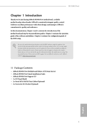
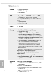
...; ASRock B550M Pro4 Quick Installation Guide • ASRock B550M Pro4 Support CD • 1 x I/O Panel Shield • 2 x Serial ATA (SATA) Data Cables (Optional) • 2 x Screws for purchasing ASRock B550M Pro4 motherboard, a reliable motherboard produced under ASRock's consistently stringent quality control. B550M Pro4 Chapter 1 Introduction Thank you are using. You may find the latest VGA cards and CPU support list on ASRock's website without notice. Chapter 3 contains the operation guide of this documentation, Chapter 1 and 2 contains the introduction of the BIOS setup.
...; ASRock B550M Pro4 Quick Installation Guide • ASRock B550M Pro4 Support CD • 1 x I/O Panel Shield • 2 x Serial ATA (SATA) Data Cables (Optional) • 2 x Screws for purchasing ASRock B550M Pro4 motherboard, a reliable motherboard produced under ASRock's consistently stringent quality control. B550M Pro4 Chapter 1 Introduction Thank you are using. You may find the latest VGA cards and CPU support list on ASRock's website without notice. Chapter 3 contains the operation guide of this documentation, Chapter 1 and 2 contains the introduction of the BIOS setup.
User Manual
Page 8
... series CPUs (Matisse) Slot • 2 x PCI Express x16 Slots (PCIE1: Gen4x16 mode; 1.2 Specifications Platform CPU • Micro ATX Form Factor • Solid Capacitor design • 2oz Copper PCB • Supports 3rd Gen AMD AM4 Ryzen™ / future AMD Ryzen™ Processors (3000 and 4000 Series Processors)* * Not compatible with AMD Ryzen™ 5 3400G and Ryzen™ 3 3200G. • Digi Power design • 8 Power Phase design Chipset • AMD B550 Memory • Dual Channel DDR4 Memory Technology...
... series CPUs (Matisse) Slot • 2 x PCI Express x16 Slots (PCIE1: Gen4x16 mode; 1.2 Specifications Platform CPU • Micro ATX Form Factor • Solid Capacitor design • 2oz Copper PCB • Supports 3rd Gen AMD AM4 Ryzen™ / future AMD Ryzen™ Processors (3000 and 4000 Series Processors)* * Not compatible with AMD Ryzen™ 5 3400G and Ryzen™ 3 3200G. • Digi Power design • 8 Power Phase design Chipset • AMD B550 Memory • Dual Channel DDR4 Memory Technology...
User Manual
Page 9
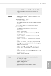
... HBR (High Bit Rate Audio) with HDMI 2.1 Port (Compliant HDMI monitor is required) • Supports HDR (High Dynamic Range) with HDMI 2.1 • Supports HDCP 2.3 with HDMI 2.1 and DisplayPort 1.4 Ports • Supports 4K Ultra HD (UHD) playback with HDMI 2.1 and DisplayPort 1.4 Ports • Supports Microsoft PlayReady® • 7.1 CH HD Audio with max. B550M Pro4 Graphics Audio • Supports AMD Quad CrossFireXTM and CrossFireXTM • 1 x M.2 Socket (Key E), supports type 2230 WiFi/BT module • Integrated AMD RadeonTM Vega Series Graphics in Ryzen Series APU...
... HBR (High Bit Rate Audio) with HDMI 2.1 Port (Compliant HDMI monitor is required) • Supports HDR (High Dynamic Range) with HDMI 2.1 • Supports HDCP 2.3 with HDMI 2.1 and DisplayPort 1.4 Ports • Supports 4K Ultra HD (UHD) playback with HDMI 2.1 and DisplayPort 1.4 Ports • Supports Microsoft PlayReady® • 7.1 CH HD Audio with max. B550M Pro4 Graphics Audio • Supports AMD Quad CrossFireXTM and CrossFireXTM • 1 x M.2 Socket (Key E), supports type 2230 WiFi/BT module • Integrated AMD RadeonTM Vega Series Graphics in Ryzen Series APU...

User Manual
Page 11
... if 3-pin or 4-pin fan is in use. • 1 x 24 pin ATX Power Connector • 1 x 8 pin 12V Power Connector • 1 x Front Panel Audio Connector • 2 x USB 2.0 Headers (Support 4 USB 2.0 ports) (Supports ESD Protection) • 2 x USB 3.2 Gen1 Headers (Support 4 USB 3.2 Gen1 ports) (Supports ESD Protection) BIOS Feature • AMI UEFI Legal BIOS with GUI support • Supports "Plug and Play" • ACPI 5.1 compliance wake up events • Supports jumperfree • SMBIOS 2.3 support • CPU, CPU VDDCR_SOC, DRAM, VPPM, 1.05V_PROM_ S5, 2.5V_PROM, +1.8VSB, VDDP Voltage...
... if 3-pin or 4-pin fan is in use. • 1 x 24 pin ATX Power Connector • 1 x 8 pin 12V Power Connector • 1 x Front Panel Audio Connector • 2 x USB 2.0 Headers (Support 4 USB 2.0 ports) (Supports ESD Protection) • 2 x USB 3.2 Gen1 Headers (Support 4 USB 3.2 Gen1 ports) (Supports ESD Protection) BIOS Feature • AMI UEFI Legal BIOS with GUI support • Supports "Plug and Play" • ACPI 5.1 compliance wake up events • Supports jumperfree • SMBIOS 2.3 support • CPU, CPU VDDCR_SOC, DRAM, VPPM, 1.05V_PROM_ S5, 2.5V_PROM, +1.8VSB, VDDP Voltage...

User Manual
Page 14
... Connector (SATA3_6) 16 System Panel Header (PANEL1) 17 Power LED and Speaker Header (SPK_PLED1) 18 USB 3.2 Gen1 Header (F_USB3_3_4) 19 Chassis/Water Pump Fan Connector (CHA_FAN4/WP) 20 Post Status Checker (PSC) 21 SPI TPM Header (SPI_TPM_J1) 22 USB 2.0 Header (USB_3_4) 23 USB 2.0 Header (USB_5_6) 24 Chassis/Water Pump Fan Connector (CHA_FAN2/WP) 25 Chassis/Water Pump Fan Connector (CHA_FAN3/WP) 26 Clear CMOS Jumper (CLRCMOS1) 27 COM Port Header (COM1) 28 Addressable LED Header (ADDR_LED2) 29 RGB LED Header (RGB_LED2) 30 Front Panel Audio Header...
... Connector (SATA3_6) 16 System Panel Header (PANEL1) 17 Power LED and Speaker Header (SPK_PLED1) 18 USB 3.2 Gen1 Header (F_USB3_3_4) 19 Chassis/Water Pump Fan Connector (CHA_FAN4/WP) 20 Post Status Checker (PSC) 21 SPI TPM Header (SPI_TPM_J1) 22 USB 2.0 Header (USB_3_4) 23 USB 2.0 Header (USB_5_6) 24 Chassis/Water Pump Fan Connector (CHA_FAN2/WP) 25 Chassis/Water Pump Fan Connector (CHA_FAN3/WP) 26 Clear CMOS Jumper (CLRCMOS1) 27 COM Port Header (COM1) 28 Addressable LED Header (ADDR_LED2) 29 RGB LED Header (RGB_LED2) 30 Front Panel Audio Header...

User Manual
Page 17
... you uninstall any motherboard settings. • Make sure to the chassis, please do so may damage the motherboard. 11 English B550M Pro4 Chapter 2 Installation This is a Micro ATX form factor motherboard. Pre-installation Precautions Take note of your chassis to the motherboard's components, NEVER place your motherboard directly on a carpet. Failure to do not overtighten the screws! Before you install motherboard components or change any components, place...
... you uninstall any motherboard settings. • Make sure to the chassis, please do so may damage the motherboard. 11 English B550M Pro4 Chapter 2 Installation This is a Micro ATX form factor motherboard. Pre-installation Precautions Take note of your chassis to the motherboard's components, NEVER place your motherboard directly on a carpet. Failure to do not overtighten the screws! Before you install motherboard components or change any components, place...

User Manual
Page 31
... power cord is used for PCI Express x16 lane width graphics cards. English 25 PCIe Slot Configurations Ryzen Series CPUs (Matisse) PCIE1 Gen4x16 PCIE2 Gen3x1 PCIE3 Gen3x4 Ryzen Series CPUs (Renoir) Gen3x16 Gen3x1 Gen3x4 For a better thermal environment, please connect a chassis fan to the motherboard's chassis fan connector (CHA_FAN1/WP, CHA_FAN2/WP , CHA_FAN3/WP or CHA_ FAN4/WP ) when using multiple graphics cards. PCIE3 (PCIe 3.0 x16 slot) is used for the card before you start the installation. PCIe slots...
... power cord is used for PCI Express x16 lane width graphics cards. English 25 PCIe Slot Configurations Ryzen Series CPUs (Matisse) PCIE1 Gen4x16 PCIE2 Gen3x1 PCIE3 Gen3x4 Ryzen Series CPUs (Renoir) Gen3x16 Gen3x1 Gen3x4 For a better thermal environment, please connect a chassis fan to the motherboard's chassis fan connector (CHA_FAN1/WP, CHA_FAN2/WP , CHA_FAN3/WP or CHA_ FAN4/WP ) when using multiple graphics cards. PCIE3 (PCIe 3.0 x16 slot) is used for the card before you start the installation. PCIe slots...

User Manual
Page 37
... CPU and not the graphics card. A TPM system also helps enhance network security, protects digital identities, and ensures platform integrity. SPI TPM Header (13-pin SPI_TPM_J1) (see p.7, No. 27) RRXD1 DDTR#1 DDSR#1 CCTS#1 1 RRI#1 RRTS#1 GND TTXD1 DDCD#1 This motherboard provides an 8-pin ATX 12V power connector. Do not plug the PCIe power cable to this connector. English 31 This COM1 header supports a serial port module. B550M Pro4 ATX 12V Power 8 5 Connector (8-pin ATX12V1) 4 1 (see p.7, No. 1) Serial Port Header (9-pin...
... CPU and not the graphics card. A TPM system also helps enhance network security, protects digital identities, and ensures platform integrity. SPI TPM Header (13-pin SPI_TPM_J1) (see p.7, No. 27) RRXD1 DDTR#1 DDSR#1 CCTS#1 1 RRI#1 RRTS#1 GND TTXD1 DDCD#1 This motherboard provides an 8-pin ATX 12V power connector. Do not plug the PCIe power cable to this connector. English 31 This COM1 header supports a serial port module. B550M Pro4 ATX 12V Power 8 5 Connector (8-pin ATX12V1) 4 1 (see p.7, No. 1) Serial Port Header (9-pin...

User Manual
Page 40
... system requires. Make sure that your graphics card driver supports AMD CrossFireXTM technology. Different CrossFireXTM cards may require different methods to the AMD's website for detailed installation guide. 2.8.1 Installing Two CrossFireXTM-Ready Graphics Cards Step 1 Insert one graphics card into PCIE1 slot and the other graphics card to two identical PCI Express x16 graphics cards. 1. Please refer to AMD graphics card manuals for details. 4. 2.8 CrossFireXTM and Quad CrossFireXTM Operation Guide This motherboard supports CrossFireXTM and Quad CrossFireXTM that allows...
... system requires. Make sure that your graphics card driver supports AMD CrossFireXTM technology. Different CrossFireXTM cards may require different methods to the AMD's website for detailed installation guide. 2.8.1 Installing Two CrossFireXTM-Ready Graphics Cards Step 1 Insert one graphics card into PCIE1 slot and the other graphics card to two identical PCI Express x16 graphics cards. 1. Please refer to AMD graphics card manuals for details. 4. 2.8 CrossFireXTM and Quad CrossFireXTM Operation Guide This motherboard supports CrossFireXTM and Quad CrossFireXTM that allows...
User Manual
Page 42
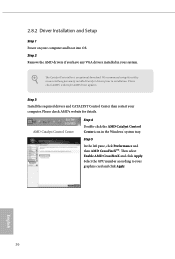
... optional download. English 36 Step 2 Remove the AMD drivers if you have any previously installed Catalyst drivers prior to your system. 2.8.2 Driver Installation and Setup Step 1 Power on your computer. We recommend using this utility to uninstall any VGA drivers installed in the Windows® system tray. Please check AMD's website for details. Step 5 In the left pane, click Performance and then AMD CrossFireXTM. Step 3 Install the required drivers and CATALYST Control...
... optional download. English 36 Step 2 Remove the AMD drivers if you have any previously installed Catalyst drivers prior to your system. 2.8.2 Driver Installation and Setup Step 1 Power on your computer. We recommend using this utility to uninstall any VGA drivers installed in the Windows® system tray. Please check AMD's website for details. Step 5 In the left pane, click Performance and then AMD CrossFireXTM. Step 3 Install the required drivers and CATALYST Control...
User Manual
Page 43
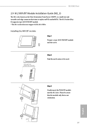
... to be used. A English A 20o 37 A Step 3 Gently insert the WiFi/BT module into the M.2 slot. B550M Pro4 2.9 M.2 WiFi/BT Module Installation Guide (M2_3) The M.2, also known as the Next Generation Form Factor (NGFF), is a small size and versatile card edge connector that the module only fits in one orientation. The M.2 Socket (Key E) supports type 2230 WiFi/BT module. * The M.2 socket does not support SATA M.2 SSDs...
... to be used. A English A 20o 37 A Step 3 Gently insert the WiFi/BT module into the M.2 slot. B550M Pro4 2.9 M.2 WiFi/BT Module Installation Guide (M2_3) The M.2, also known as the Next Generation Form Factor (NGFF), is a small size and versatile card edge connector that the module only fits in one orientation. The M.2 Socket (Key E) supports type 2230 WiFi/BT module. * The M.2 socket does not support SATA M.2 SSDs...
User Manual
Page 51
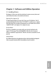
... install those required drivers. Therefore, the drivers you install can work properly. B550M Pro4 Chapter 3 Software and Utilities Operation 3.1 Installing Drivers The Support CD that comes with the motherboard contains necessary drivers and useful utilities that the motherboard supports. Click on the support CD driver page. The CD automatically displays the Main Menu if "AUTORUN" is enabled in the Support CD to your CD-ROM drive. If the Main Menu does not appear automatically, locate and double click on the file...
... install those required drivers. Therefore, the drivers you install can work properly. B550M Pro4 Chapter 3 Software and Utilities Operation 3.1 Installing Drivers The Support CD that comes with the motherboard contains necessary drivers and useful utilities that the motherboard supports. Click on the support CD driver page. The CD automatically displays the Main Menu if "AUTORUN" is enabled in the Support CD to your CD-ROM drive. If the Main Menu does not appear automatically, locate and double click on the file...

User Manual
Page 68
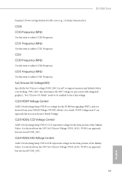
... and the drivers required before overclocking, or else your screen. CPU Core (Per CCX) CPU Voltage Specifies a custom CPU core voltage (mV), Should be set up overclocking features. 4.3 OC Tweaker Screen In the OC Tweaker screen, you see on your HDD's may be undetectable. Because the UEFI software is connected via the onboard D-Bus/VGA connector. Overclock Mode(Bus Speed) Select the overclock mode. CPU Frequency and Voltage(VID) Change If this item is depending on user selection. When overclocking also the PCIe, PCI, SATA and USB busses...
... and the drivers required before overclocking, or else your screen. CPU Core (Per CCX) CPU Voltage Specifies a custom CPU core voltage (mV), Should be set up overclocking features. 4.3 OC Tweaker Screen In the OC Tweaker screen, you see on your HDD's may be undetectable. Because the UEFI software is connected via the onboard D-Bus/VGA connector. Overclock Mode(Bus Speed) Select the overclock mode. CPU Frequency and Voltage(VID) Change If this item is depending on user selection. When overclocking also the PCIe, PCI, SATA and USB busses...
User Manual
Page 69
... also determines the GPU voltage on processors with integrated graphics. CLD0 VDDG CCD Voltage Control AMD Overclocking Setup VDDG CCD represents voltage for the DDR4 bus signaling (PHY), and it is derived from the CPU SoC/Uncore Voltage (VDD_SOC). CCD0 CCX0 Frequency (MHz) Use this item to support memory and Infinity Fabric overclocking. CCX1 Frequency (MHz) Use this voltage. It is derived from your DRAM Voltage. It is a voltage for the data portion...
... also determines the GPU voltage on processors with integrated graphics. CLD0 VDDG CCD Voltage Control AMD Overclocking Setup VDDG CCD represents voltage for the DDR4 bus signaling (PHY), and it is derived from the CPU SoC/Uncore Voltage (VDD_SOC). CCD0 CCX0 Frequency (MHz) Use this item to support memory and Infinity Fabric overclocking. CCX1 Frequency (MHz) Use this voltage. It is derived from your DRAM Voltage. It is a voltage for the data portion...


