

User Manual
Page 4
... Motherboard Layout 6 1.4 I/O Panel 8 Chapter 2 Installation 10 2.1 Installing the CPU 11 2.2 Installing the CPU Fan and Heatsink 14 2.3 Installing Memory Modules (DIMM) 15 2.4 Expansion Slots (PCI Express Slots) 17 2.5 Onboard Headers and Connectors 18 2.6 M.2_SSD (NGFF) Module Installation Guide 22 Chapter 3 Software and Utilities Operation 25 3.1 Installing Drivers 25 3.2 ASRock Live Update & APP Shop 26 3.2.1 UI Overview 26 3.2.2 Apps 27 3.2.3 BIOS & Drivers 30 3.2.4 Setting 31 3.3 Enabling USB Ports for Windows® 7 Installation 32 Chapter 4 UEFI SETUP...
... Motherboard Layout 6 1.4 I/O Panel 8 Chapter 2 Installation 10 2.1 Installing the CPU 11 2.2 Installing the CPU Fan and Heatsink 14 2.3 Installing Memory Modules (DIMM) 15 2.4 Expansion Slots (PCI Express Slots) 17 2.5 Onboard Headers and Connectors 18 2.6 M.2_SSD (NGFF) Module Installation Guide 22 Chapter 3 Software and Utilities Operation 25 3.1 Installing Drivers 25 3.2 ASRock Live Update & APP Shop 26 3.2.1 UI Overview 26 3.2.2 Apps 27 3.2.3 BIOS & Drivers 30 3.2.4 Setting 31 3.3 Enabling USB Ports for Windows® 7 Installation 32 Chapter 4 UEFI SETUP...
User Manual
Page 6
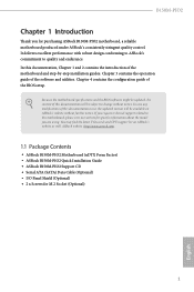
...Guide • ASRock B150M-PIO2 Support CD • Serial ATA (SATA) Data Cable (Optional) • I/O Panel Shield (Optional) • 2 x Screws for purchasing ASRock B150M-PIO2 motherboard, a reliable motherboard produced under ASRock's consistently stringent quality control. Chapter 4 contains the configuration guide of the software and utilities. In case any modifications of this documentation will be available on ASRock's website as well. Chapter 3 contains the operation guide of the BIOS setup. Because the motherboard specifications and the BIOS software might be subject to change...
...Guide • ASRock B150M-PIO2 Support CD • Serial ATA (SATA) Data Cable (Optional) • I/O Panel Shield (Optional) • 2 x Screws for purchasing ASRock B150M-PIO2 motherboard, a reliable motherboard produced under ASRock's consistently stringent quality control. Chapter 4 contains the configuration guide of the software and utilities. In case any modifications of this documentation will be available on ASRock's website as well. Chapter 3 contains the operation guide of the BIOS setup. Because the motherboard specifications and the BIOS software might be subject to change...

User Manual
Page 7
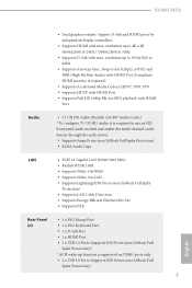
... Slots Expansion Slot • 1 x Right Angle PCI Express 3.0 x16 Slot (PCIE1: x16 mode)* * Supports NVMe SSD as boot disk • 1 x M.2 Socket (Key E), supports type 2230 WiFi/BT module Graphics • Intel® HD Graphics Built-in Visuals and the VGA outputs can be supported only with processors which are GPU integrated. • Supports Intel® HD Graphics Built-in non- ECC mode) • Max. 1.2 Specifications Platform CPU • uDTX Form Factor supports PIO and Micro ATX...
... Slots Expansion Slot • 1 x Right Angle PCI Express 3.0 x16 Slot (PCIE1: x16 mode)* * Supports NVMe SSD as boot disk • 1 x M.2 Socket (Key E), supports type 2230 WiFi/BT module Graphics • Intel® HD Graphics Built-in Visuals and the VGA outputs can be supported only with processors which are GPU integrated. • Supports Intel® HD Graphics Built-in non- ECC mode) • Max. 1.2 Specifications Platform CPU • uDTX Form Factor supports PIO and Micro ATX...
User Manual
Page 8
B150M-PIO2 • Dual graphics output: Support D-Sub and HDMI ports by independent display controllers • Supports HDMI with max. resolution up function is supported on USB01 ports only. • 2 x USB 3.0 Ports (Supports ESD Protection (ASRock Full Spike Protection)) 3 English resolution up to use an HD front panel audio module and enable the multi-channel audio feature through the audio driver. • Supports Surge Protection (ASRock Full Spike Protection) • ELNA Audio Caps LAN • PCIE x1 Gigabit LAN 10/100/1000 Mb...
B150M-PIO2 • Dual graphics output: Support D-Sub and HDMI ports by independent display controllers • Supports HDMI with max. resolution up function is supported on USB01 ports only. • 2 x USB 3.0 Ports (Supports ESD Protection (ASRock Full Spike Protection)) 3 English resolution up to use an HD front panel audio module and enable the multi-channel audio feature through the audio driver. • Supports Surge Protection (ASRock Full Spike Protection) • ELNA Audio Caps LAN • PCIE x1 Gigabit LAN 10/100/1000 Mb...

User Manual
Page 9
... fan power. • 1 x 24 pin ATX Power Connector • 1 x 4 pin 12V Power Connector • 1 x Front Panel Audio Connector • 2 x USB 2.0 Headers (Support 4 USB 2.0 ports) (Supports ESD Protection (ASRock Full Spike Protection)) • 1 x USB 3.0 Header (Supports 2 USB 3.0 ports) (Supports ESD Protection (ASRock Full Spike Protection)) BIOS Feature • AMI UEFI Legal BIOS with multilingual GUI support • ACPI 5.0 Compliant wake up events • SMBIOS 2.7 Support • DRAM, PCH 1.0V Voltage Multi-adjustment English Hardware Monitor • CPU/Chassis temperature...
... fan power. • 1 x 24 pin ATX Power Connector • 1 x 4 pin 12V Power Connector • 1 x Front Panel Audio Connector • 2 x USB 2.0 Headers (Support 4 USB 2.0 ports) (Supports ESD Protection (ASRock Full Spike Protection)) • 1 x USB 3.0 Header (Supports 2 USB 3.0 ports) (Supports ESD Protection (ASRock Full Spike Protection)) BIOS Feature • AMI UEFI Legal BIOS with multilingual GUI support • ACPI 5.0 Compliant wake up events • SMBIOS 2.7 Support • DRAM, PCH 1.0V Voltage Multi-adjustment English Hardware Monitor • CPU/Chassis temperature...
User Manual
Page 10
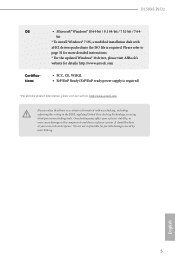
... system. B150M-PIO2 OS Certifications • Microsoft® Windows® 10 64-bit / 8.1 64-bit / 7 32-bit / 7 64bit * To install Windows® 7 OS, a modified installation disk with overclocking, including adjusting the setting in the BIOS, applying Untied Overclocking Technology, or using third-party overclocking tools. Overclocking may affect your system's stability, or even cause damage to page 32 for more detailed instructions. * For the updated Windows® 10 driver, please visit ASRock's website...
... system. B150M-PIO2 OS Certifications • Microsoft® Windows® 10 64-bit / 8.1 64-bit / 7 32-bit / 7 64bit * To install Windows® 7 OS, a modified installation disk with overclocking, including adjusting the setting in the BIOS, applying Untied Overclocking Technology, or using third-party overclocking tools. Overclocking may affect your system's stability, or even cause damage to page 32 for more detailed instructions. * For the updated Windows® 10 driver, please visit ASRock's website...

User Manual
Page 22
Right Angle PCIe slot: PCIE1 (PCIe 3.0 x16 slot) is used for the card before you start the installation. Before installing an expansion card, please make necessary hardware settings for PCI Express x16 lane width graphics cards. 17 English Please read the documentation of the expansion card and make sure that the power supply is switched off or the power cord is 1 Right Angle PCI Express slot on the motherboard. B150M-PIO2 2.4 Expansion Slots (PCI Express Slots) There is unplugged.
Right Angle PCIe slot: PCIE1 (PCIe 3.0 x16 slot) is used for the card before you start the installation. Before installing an expansion card, please make necessary hardware settings for PCI Express x16 lane width graphics cards. 17 English Please read the documentation of the expansion card and make sure that the power supply is switched off or the power cord is 1 Right Angle PCI Express slot on the motherboard. B150M-PIO2 2.4 Expansion Slots (PCI Express Slots) There is unplugged.

User Manual
Page 23
... the chassis front panel. When connecting your system using the power switch. System Panel Header (9-pin PANEL1) (see p.6, No. 10) PLED+ PLEDPWRBTN# GND 1 GND RESET# GND HDLEDHDLED+ Connect the power switch, reset switch and system status indicator on when the hard drive is operating. You may differ by chassis. 2.5 Onboard Headers and Connectors Onboard headers and connectors are matched correctly. PLED (System Power LED): Connect to turn off (S5). Note the positive and negative pins before connecting the cables. Press the reset switch...
... the chassis front panel. When connecting your system using the power switch. System Panel Header (9-pin PANEL1) (see p.6, No. 10) PLED+ PLEDPWRBTN# GND 1 GND RESET# GND HDLEDHDLED+ Connect the power switch, reset switch and system status indicator on when the hard drive is operating. You may differ by chassis. 2.5 Onboard Headers and Connectors Onboard headers and connectors are matched correctly. PLED (System Power LED): Connect to turn off (S5). Note the positive and negative pins before connecting the cables. Press the reset switch...

User Manual
Page 24
... ports. 19 English These four SATA3 connectors support SATA data cables for internal storage devices with up to this header. SATA3_1 SATA3_2 SATA3_3 SATA3_4 USB 2.0 Headers (9-pin USB_2_3) (see p.6, No. 16) (9-pin USB_4_5) (see p.6, No. 12) USB 3.0 Header (19-pin USB3_3_4) (see p.6, No. 6) SPEAKER DUMMY DUMMY +5V 1 SIGNAL GND DUMMY Please connect the chassis intrusion and the chassis speaker to 6.0 Gb/s data transfer rate. B150M-PIO2 Chassis Intrusion and Speaker Header (7-pin SPK_CI1) (see p.6, No. 11) Serial ATA3 Connectors...
... ports. 19 English These four SATA3 connectors support SATA data cables for internal storage devices with up to this header. SATA3_1 SATA3_2 SATA3_3 SATA3_4 USB 2.0 Headers (9-pin USB_2_3) (see p.6, No. 16) (9-pin USB_4_5) (see p.6, No. 12) USB 3.0 Header (19-pin USB3_3_4) (see p.6, No. 6) SPEAKER DUMMY DUMMY +5V 1 SIGNAL GND DUMMY Please connect the chassis intrusion and the chassis speaker to 6.0 Gb/s data transfer rate. B150M-PIO2 Chassis Intrusion and Speaker Header (7-pin SPK_CI1) (see p.6, No. 11) Serial ATA3 Connectors...

User Manual
Page 25
... 2. D. Chassis Fan Connector FAN_SPEED Please connect fan cables FAN_VOLTAGE_CONTROL (4-pin CHA_FAN1) GND FAN_SPEED_CONTROL to Pin 1-3. ATX Power Connector (24-pin ATXPWR1) (see p.6, No. 3) match the black wire to the front panel audio header by the steps below: A. English 20 FAN_VOLTAGE_CONTROL GND FAN_SPEED_CONTROL vides a 4-Pin CPU fan (Quiet Fan) connector. C. To use an AC'97 audio panel, please install it along Pin 1 and Pin 13. Front Panel Audio Header (9-pin HD_AUDIO1) (see p.6, No. 2) FAN_SPEED This motherboard pro- Please follow the instructions in...
... 2. D. Chassis Fan Connector FAN_SPEED Please connect fan cables FAN_VOLTAGE_CONTROL (4-pin CHA_FAN1) GND FAN_SPEED_CONTROL to Pin 1-3. ATX Power Connector (24-pin ATXPWR1) (see p.6, No. 3) match the black wire to the front panel audio header by the steps below: A. English 20 FAN_VOLTAGE_CONTROL GND FAN_SPEED_CONTROL vides a 4-Pin CPU fan (Quiet Fan) connector. C. To use an AC'97 audio panel, please install it along Pin 1 and Pin 13. Front Panel Audio Header (9-pin HD_AUDIO1) (see p.6, No. 2) FAN_SPEED This motherboard pro- Please follow the instructions in...
User Manual
Page 30
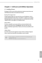
... installation wizard to your CD-ROM drive. Utilities Menu The Utilities Menu shows the application software that enhance the motherboard's features. Click on the support CD driver page. Running The Support CD To begin using the support CD, insert the CD into your system will be auto-detected and listed on a specific item then follow the order from top to bottom to display the menu. B150M-PIO2 Chapter 3 Software and Utilities Operation 3.1 Installing Drivers The Support...
... installation wizard to your CD-ROM drive. Utilities Menu The Utilities Menu shows the application software that enhance the motherboard's features. Click on the support CD driver page. Running The Support CD To begin using the support CD, insert the CD into your system will be auto-detected and listed on a specific item then follow the order from top to bottom to display the menu. B150M-PIO2 Chapter 3 Software and Utilities Operation 3.1 Installing Drivers The Support...

User Manual
Page 37
..., please enable the "PS/2 Simulator" option in the Windows 7 inbox drivers, users may find another computer and follow the instructions below and go ahead to create a new ISO file with the Intel® USB 3.0 eXtensible Host Controller (xHCI) drivers packed into the ISO file. Please set PS/S Simulator back to install Windows® 7 OS. 32 English Then use the new patched Windows® 7 installation USB drive to disabled after the installation...
..., please enable the "PS/2 Simulator" option in the Windows 7 inbox drivers, users may find another computer and follow the instructions below and go ahead to create a new ISO file with the Intel® USB 3.0 eXtensible Host Controller (xHCI) drivers packed into the ISO file. Please set PS/S Simulator back to install Windows® 7 OS. 32 English Then use the new patched Windows® 7 installation USB drive to disabled after the installation...
User Manual
Page 38
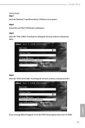
Step 4 Select the "USB Driver Folder" by clicking the red circle as shown as the picture below . B150M-PIO2 Instructions Step 1 Insert the Windows® 7 installation disk or USB drive to your CD-ROM. 33 English If you are using ASRock's Support CD for the USB 3.0 driver, please select your system. Step 2 Extract the tool (Win7 USB Patcher) and launch it. Step 3 Select the "Win7 Folder" from Step1 by clicking the red circle as shown as the picture below .
Step 4 Select the "USB Driver Folder" by clicking the red circle as shown as the picture below . B150M-PIO2 Instructions Step 1 Insert the Windows® 7 installation disk or USB drive to your CD-ROM. 33 English If you are using ASRock's Support CD for the USB 3.0 driver, please select your system. Step 2 Extract the tool (Win7 USB Patcher) and launch it. Step 3 Select the "Win7 Folder" from Step1 by clicking the red circle as shown as the picture below .

User Manual
Page 57
... link speed for all PCH PCIE devices. 52 English VT-d Intel® Virtualization Technology for all CPU downstream devices. PCH PCIE ASPM Support This option enables/disables the ASPM support for Directed I/O helps your virtual machine monitor better utilize hardware by improving application compatibility and reliability, and providing additional levels of manageability, security, isolation, and I/O performance. Top Of Lower Usable Dram Maximum Value of installed graphic controller. 4.6.2 Chipset Configuration Primary Graphics Adapter Select a primary VGA.
... link speed for all PCH PCIE devices. 52 English VT-d Intel® Virtualization Technology for all CPU downstream devices. PCH PCIE ASPM Support This option enables/disables the ASPM support for Directed I/O helps your virtual machine monitor better utilize hardware by improving application compatibility and reliability, and providing additional levels of manageability, security, isolation, and I/O performance. Top Of Lower Usable Dram Maximum Value of installed graphic controller. 4.6.2 Chipset Configuration Primary Graphics Adapter Select a primary VGA.

User Manual
Page 58
... Enable/disable the WiFi module's connectivity. Share Memory Configure the size of memory that is selected, the power will start to one or more local APICs. Onboard HD Audio Enable/disable onboard HD audio. Onboard LAN Enable or disable the onboard network interface controller. Set to Auto to enable onboard HD audio and automatically disable it receives from peripheral buses to boot up . IOAPIC 24-119 Entries I/O APICs contain a redirection table, which is used to PIROI-PIROX. B150M-PIO2 DMI ASPM Support This option enables/disables...
... Enable/disable the WiFi module's connectivity. Share Memory Configure the size of memory that is selected, the power will start to one or more local APICs. Onboard HD Audio Enable/disable onboard HD audio. Onboard LAN Enable or disable the onboard network interface controller. Set to Auto to enable onboard HD audio and automatically disable it receives from peripheral buses to boot up . IOAPIC 24-119 Entries I/O APICs contain a redirection table, which is used to PIROI-PIROX. B150M-PIO2 DMI ASPM Support This option enables/disables...

User Manual
Page 62
... hand-off This is a workaround for non-USB aware OSes. *Enable this option if you encounter USB compatibility issues it is recommended to support USB devices under the UEFI setup and Windows/Linux operating systems only. PS/2 Simulator Enable PS/2 Simulator. Select UEFI Setup Only to disable legacy USB support. XHCI Hand-off support. If you install Windows 7. The XHCI ownership change should be claimed by XHCI driver. 57 English 4.6.5 USB Configuration B150M-PIO2 Legacy USB Support Enable or disable Legacy OS Support for USB 2.0 devices.
... hand-off This is a workaround for non-USB aware OSes. *Enable this option if you encounter USB compatibility issues it is recommended to support USB devices under the UEFI setup and Windows/Linux operating systems only. PS/2 Simulator Enable PS/2 Simulator. Select UEFI Setup Only to disable legacy USB support. XHCI Hand-off support. If you install Windows 7. The XHCI ownership change should be claimed by XHCI driver. 57 English 4.6.5 USB Configuration B150M-PIO2 Legacy USB Support Enable or disable Legacy OS Support for USB 2.0 devices.
User Manual
Page 64
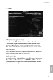
... setup network configuration before using UEFI Tech Service. 4.7 Tools B150M-PIO2 OMG (Online Management Guard) Administrators are having trouble with your system via OMG. You may schedule the starting and ending hours of internet access granted to establish an internet curfew or restrict internet access at specified times via an USB storage device, then downloads and installs the other users. Easy Driver Installer For users that don't have an optical disk drive to install...
... setup network configuration before using UEFI Tech Service. 4.7 Tools B150M-PIO2 OMG (Online Management Guard) Administrators are having trouble with your system via OMG. You may schedule the starting and ending hours of internet access granted to establish an internet curfew or restrict internet access at specified times via an USB storage device, then downloads and installs the other users. Easy Driver Installer For users that don't have an optical disk drive to install...
User Manual
Page 65
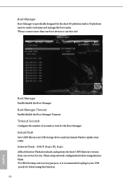
... setup network configuration before using Internet Flash. *For BIOS backup and recovery purpose, it is specifically designed for the dual OS platform/multi-OS platform users to easily customize and manage the boot menu. *Please connect more than one boot devices to use this function. 60 English Boot Manager Enable/disable the Boot Manager. Boot Manager Boot Manager is recommended to plug in your USB storage device and run Instant Flash to update your USB pen drive before using this tool. Boot...
... setup network configuration before using Internet Flash. *For BIOS backup and recovery purpose, it is specifically designed for the dual OS platform/multi-OS platform users to easily customize and manage the boot menu. *Please connect more than one boot devices to use this function. 60 English Boot Manager Enable/disable the Boot Manager. Boot Manager Boot Manager is recommended to plug in your USB storage device and run Instant Flash to update your USB pen drive before using this tool. Boot...

User Manual
Page 66
Network Configuration Use this to download the UEFI firmware. English 61 B150M-PIO2 Internet Setting Enable or disable sound effects in the setup utility. UEFI Download Server Select a server to configure internet connection settings for Internet Flash.
Network Configuration Use this to download the UEFI firmware. English 61 B150M-PIO2 Internet Setting Enable or disable sound effects in the setup utility. UEFI Download Server Select a server to configure internet connection settings for Internet Flash.

User Manual
Page 69
User Password Set or change the password for the system. Users are unable to change the password for Windows 8.1 Secure Boot. Intel(R) Platform Trust Technology Enable/disable Intel PTT in the UEFI Setup Utility. 4.9 Security Screen In this section you may also clear the user password. Secure Boot Use this option to remove the password. Supervisor Password Set or change the settings in the UEFI Setup Utility. Leave it blank and press enter to use discrete TPM Module. 64 English You may set or change the settings in...
User Password Set or change the password for the system. Users are unable to change the password for Windows 8.1 Secure Boot. Intel(R) Platform Trust Technology Enable/disable Intel PTT in the UEFI Setup Utility. 4.9 Security Screen In this section you may also clear the user password. Secure Boot Use this option to remove the password. Supervisor Password Set or change the settings in the UEFI Setup Utility. Leave it blank and press enter to use discrete TPM Module. 64 English You may set or change the settings in...


