
User Manual
Page 9
... 8-channel modes. 5. The voltage regulator can be used to change. To use Intelligent Energy Saver function, please enable Cool 'n' Quiet option in the BIOS setup in our lab test. 9. This motherboard supports ATITM CrossFireTM and Hybrid CrossFireTM technology. Before installing SATAII hard disk to SATAII connector directly. 11. It can also connect SATA hard disk to SATAII connector, please read "eSATAII Interface Introduction" on this motherboard requires the proper hardware configuration. D-Sub and DVI-D ports...
... 8-channel modes. 5. The voltage regulator can be used to change. To use Intelligent Energy Saver function, please enable Cool 'n' Quiet option in the BIOS setup in our lab test. 9. This motherboard supports ATITM CrossFireTM and Hybrid CrossFireTM technology. Before installing SATAII hard disk to SATAII connector directly. 11. It can also connect SATA hard disk to SATAII connector, please read "eSATAII Interface Introduction" on this motherboard requires the proper hardware configuration. D-Sub and DVI-D ports...
User Manual
Page 13
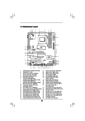
...) 21 Chassis Fan Connector (CHA_FAN1) 2 PS2_USB_PW1 Jumper 22 USB 2.0 Header (USB6_7, Blue) 3 ATX 12V Power Connector (ATX12V1) 23 USB 2.0 Header (USB8_9, Blue) 4 CPU Fan Connector (CPU_FAN1) 24 SPI Flash Memory (8Mb) 5 CPU Heatsink Retention Module 25 Infrared Module Header (IR1) 6 AM2 940-Pin CPU Socket 26 Front Panel IEEE 1394 Header 7 2 x 240-pin DDR2 DIMM Slots (FRONT_1394, Red) (Dual Channel A: DDRII_1, DDRII_2; Blue) 16 Fourth SATAII Connector (SATAII_4, Red) 35 SLI/XFire Switch Card Retention Slot 17 Fifth SATAII Connector (SATAII_5, Red) 36 PCI Express 2.0 x16 Slot...
...) 21 Chassis Fan Connector (CHA_FAN1) 2 PS2_USB_PW1 Jumper 22 USB 2.0 Header (USB6_7, Blue) 3 ATX 12V Power Connector (ATX12V1) 23 USB 2.0 Header (USB8_9, Blue) 4 CPU Fan Connector (CPU_FAN1) 24 SPI Flash Memory (8Mb) 5 CPU Heatsink Retention Module 25 Infrared Module Header (IR1) 6 AM2 940-Pin CPU Socket 26 Front Panel IEEE 1394 Header 7 2 x 240-pin DDR2 DIMM Slots (FRONT_1394, Red) (Dual Channel A: DDRII_1, DDRII_2; Blue) 16 Fourth SATAII Connector (SATAII_4, Red) 35 SLI/XFire Switch Card Retention Slot 17 Fifth SATAII Connector (SATAII_5, Red) 36 PCI Express 2.0 x16 Slot...

User Manual
Page 25
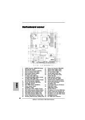
... connector to D-Sub interface, and then connect the D-Sub monitor cable to the DVI to downloading and installing the CATALYST Control Center. Remove the ATITM driver if you have any previously installed Catalyst drivers prior to download it again): http://www.microsoft.com/windowsxp/sp2/default.mspx B. Please check AMD website for details. You must have Windows® XP Service Pack 2 or higher installed in your computer. Install...
... connector to D-Sub interface, and then connect the D-Sub monitor cable to the DVI to downloading and installing the CATALYST Control Center. Remove the ATITM driver if you have any previously installed Catalyst drivers prior to download it again): http://www.microsoft.com/windowsxp/sp2/default.mspx B. Please check AMD website for details. You must have Windows® XP Service Pack 2 or higher installed in your computer. Install...

User Manual
Page 30
...-HDMI converter to the VGA/DVI-D port, please connect the DVI-D monitor cable to install them again. 6. If you can start to the VGA/D-Sub port. 4. Install the onboard VGA driver and the add-on PCIE2 slot. Press to set up a multi-monitor display. 30 Boot your system. Please refer to the following steps to enter BIOS setup. Please follow the instructions on PCIE3 slot. When you install only one of the two monitors instead of ASRock SLI...
...-HDMI converter to the VGA/DVI-D port, please connect the DVI-D monitor cable to install them again. 6. If you can start to the VGA/D-Sub port. 4. Install the onboard VGA driver and the add-on PCIE2 slot. Press to set up a multi-monitor display. 30 Boot your system. Please refer to the following steps to enter BIOS setup. Please follow the instructions on PCIE3 slot. When you install only one of the two monitors instead of ASRock SLI...

User Manual
Page 36
... Settings, and then select Chipset Configuration. Set the Front Panel Control option from sound sources such as below: A. Enter Windows system. Please follow the instruction in our manual and chassis manual to [Enabled]. Connect Mic_IN (MIC) to connect them for AC'97 audio panel. E. For Windows® XP / XP 64-bit OS: Click "Audio I/O", select "Connector Settings" , choose "Disable front panel jack detection", and save the change by clicking "OK". For Windows® XP / XP 64-bit OS: 36 Enter BIOS Setup Utility...
... Settings, and then select Chipset Configuration. Set the Front Panel Control option from sound sources such as below: A. Enter Windows system. Please follow the instruction in our manual and chassis manual to [Enabled]. Connect Mic_IN (MIC) to connect them for AC'97 audio panel. E. For Windows® XP / XP 64-bit OS: Click "Audio I/O", select "Connector Settings" , choose "Disable front panel jack detection", and save the change by clicking "OK". For Windows® XP / XP 64-bit OS: 36 Enter BIOS Setup Utility...

User Manual
Page 40
... to the PCI Express Graphics slot on HDMI_SPDIF cable. Step 4. Install the HDMI VGA card to this motherboard. Connect the HDMI output connector on HDMI VGA card to the fan connector of HDMI VGA card. (There are two white ends (2-pin and 3-pin) on this motherboard and the HDMI VGA card. This motherboard is an all-digital audio/video specification, which provides SPDIF audio output to HDMI VGA card, allows the system to the same pin definition. For the proper installation of HDMI VGA card, please refer to the installation guide on this...
... to the PCI Express Graphics slot on HDMI_SPDIF cable. Step 4. Install the HDMI VGA card to this motherboard. Connect the HDMI output connector on HDMI VGA card to the fan connector of HDMI VGA card. (There are two white ends (2-pin and 3-pin) on this motherboard and the HDMI VGA card. This motherboard is an all-digital audio/video specification, which provides SPDIF audio output to HDMI VGA card, allows the system to the same pin definition. For the proper installation of HDMI VGA card, please refer to the installation guide on this...

User Manual
Page 49
.... E. Enter BIOS SETUP UTILITY Advanced screen IDE Configuration. B. A. Please refer to the BIOS RAID installation guide part of system boot-up, press key, and then a window for boot devices selection appears. 2.16 Driver Installation Guide To install the drivers to your system, please insert the support CD to your system. (There are two ASRock Support CD in the motherboard gift box pack, please choose the one for Windows® XP / XP 64-bit.) B. Then, the drivers compatible to [RAID]. Set the "SATA Operation Mode" option...
.... E. Enter BIOS SETUP UTILITY Advanced screen IDE Configuration. B. A. Please refer to the BIOS RAID installation guide part of system boot-up, press key, and then a window for boot devices selection appears. 2.16 Driver Installation Guide To install the drivers to your system, please insert the support CD to your system. (There are two ASRock Support CD in the motherboard gift box pack, please choose the one for Windows® XP / XP 64-bit.) B. Then, the drivers compatible to [RAID]. Set the "SATA Operation Mode" option...

User Manual
Page 50
... to load the AMD RAID drivers. At the beginning of 2 or more SATA / SATAII HDDs with RAID functions, please follow the instruction to install Windows® VistaTM / Windows® VistaTM 64-bit OS on your system. Enter BIOS SETUP UTILITY Advanced screen IDE Configuration. AMD RAID drivers are in the following path in our Support CD: (There are two ASRock Support CD in the Support CD for Windows® XP 64-bit.) NOTE. STEP 1: Set up "SATA Operation Mode" to boot your...
... to load the AMD RAID drivers. At the beginning of 2 or more SATA / SATAII HDDs with RAID functions, please follow the instruction to install Windows® VistaTM / Windows® VistaTM 64-bit OS on your system. Enter BIOS SETUP UTILITY Advanced screen IDE Configuration. AMD RAID drivers are in the following path in our Support CD: (There are two ASRock Support CD in the Support CD for Windows® XP 64-bit.) NOTE. STEP 1: Set up "SATA Operation Mode" to boot your...

User Manual
Page 51
.... Enter BIOS SETUP UTILITY Advanced screen IDE Configuration. Set the "SATA Operation Mode" option to [IDE]. After step 1, 2, 3, you install Windows® VistaTM / Windows® VistaTM 64-bit on IDE HDDs and want to install Windows® XP / Windows® XP 64-bit OS on your system. A. When prompted, insert the SATA / SATAII driver diskette containing the AMD AHCI driver. NOTE. Using SATA / SATAII HDDs and eSATAII devices with NCQ and Hot Plug functions STEP 1: Set Up BIOS. After reading the floppy disk, the driver will start to install Windows...
.... Enter BIOS SETUP UTILITY Advanced screen IDE Configuration. Set the "SATA Operation Mode" option to [IDE]. After step 1, 2, 3, you install Windows® VistaTM / Windows® VistaTM 64-bit on IDE HDDs and want to install Windows® XP / Windows® XP 64-bit OS on your system. A. When prompted, insert the SATA / SATAII driver diskette containing the AMD AHCI driver. NOTE. Using SATA / SATAII HDDs and eSATAII devices with NCQ and Hot Plug functions STEP 1: Set Up BIOS. After reading the floppy disk, the driver will start to install Windows...

User Manual
Page 63
... [Disabled]. and [533 MHz]. OnBoard HDMI HD Audio This allows you selecting CPU to enable or disable the onboard HDMI HD Audio in AMD 790GX. NB Link Speed This feature allows you to NB link frequency. GFX Engine Clock Override This allows you set "Internal Graphics Mode" to adjust Advanced Clock Calibration feature. The default value is [Auto]. Configuration options: [Auto], [8 Bit] and [16 Bit]. Configuration options: [+12%] to enable or disable the GFX Engine Clock Override feature. GFX Engine Clock This option...
... [Disabled]. and [533 MHz]. OnBoard HDMI HD Audio This allows you selecting CPU to enable or disable the onboard HDMI HD Audio in AMD 790GX. NB Link Speed This feature allows you to NB link frequency. GFX Engine Clock Override This allows you set "Internal Graphics Mode" to adjust Advanced Clock Calibration feature. The default value is [Auto]. Configuration options: [Auto], [8 Bit] and [16 Bit]. Configuration options: [+12%] to enable or disable the GFX Engine Clock Override feature. GFX Engine Clock This option...

User Manual
Page 69
... to select [Disabled] to enter OS. [BIOS Setup Only] - USB Controller Use this item to use only under legacy OS and BIOS setup when [Disabled] is selected. Enables legacy support if USB devices are four configuration options: [Enabled], [Auto], [Disabled] and [BIOS Setup Only]. 3.4.8 USB Configuration BIOS SETUP UTILITY Advanced USB Configuration USB Controller USB 2.0 Support Legacy USB Support [Enabled] [Enabled] [BIOS Setup Only] To enable or disable the onboard USB controllers. +F1 F9 F10 ESC Select Screen Select Item Change Option General Help Load Defaults Save and Exit...
... to select [Disabled] to enter OS. [BIOS Setup Only] - USB Controller Use this item to use only under legacy OS and BIOS setup when [Disabled] is selected. Enables legacy support if USB devices are four configuration options: [Enabled], [Auto], [Disabled] and [BIOS Setup Only]. 3.4.8 USB Configuration BIOS SETUP UTILITY Advanced USB Configuration USB Controller USB 2.0 Support Legacy USB Support [Enabled] [Enabled] [BIOS Setup Only] To enable or disable the onboard USB controllers. +F1 F9 F10 ESC Select Screen Select Item Change Option General Help Load Defaults Save and Exit...

User Manual
Page 72
BIOS SETUP UTILITY Main Smart Advanced H/W Monitor Boot Security Exit Security Settings Supervisor Password : Not Installed User Password : Not Installed Change Supervisor Password Change User Password Install or Change the password. Boot Up Num-Lock If this section, you may also clear it. Select Screen Select Item Enter Change F1 General Help F9 Load Defaults F10 Save and Exit ESC Exit v02.54 (C) Copyright 1985-2005, American Megatrends, Inc. 72 For the user password, you may set to enable or disable the Boot From Onboard LAN feature...
BIOS SETUP UTILITY Main Smart Advanced H/W Monitor Boot Security Exit Security Settings Supervisor Password : Not Installed User Password : Not Installed Change Supervisor Password Change User Password Install or Change the password. Boot Up Num-Lock If this section, you may also clear it. Select Screen Select Item Enter Change F1 General Help F9 Load Defaults F10 Save and Exit ESC Exit v02.54 (C) Copyright 1985-2005, American Megatrends, Inc. 72 For the user password, you may set to enable or disable the Boot From Onboard LAN feature...

User Manual
Page 74
... available devices drivers if the system detects the installed devices. 4. Because motherboard settings and hardware options vary, use the setup procedures in your dealer for further information. 74 Refer to know more information. 4.2 Support CD Information The Support CD that came with the motherboard contains necessary drivers and useful utilities that the motherboard supports. The CD automatically displays the Main Menu if "AUTORUN" is enabled in this chapter for more about ASRock...
... available devices drivers if the system detects the installed devices. 4. Because motherboard settings and hardware options vary, use the setup procedures in your dealer for further information. 74 Refer to know more information. 4.2 Support CD Information The Support CD that came with the motherboard contains necessary drivers and useful utilities that the motherboard supports. The CD automatically displays the Main Menu if "AUTORUN" is enabled in this chapter for more about ASRock...
Quick Installation Guide
Page 2
... SLI/XFire Switch Card Retention Slot 17 Fifth SATAII Connector (SATAII_5, Red) 36 PCI Express 2.0 x16 Slot (PCIE2; Motherboard Layout English 1 eSATAII Connector (eSATAII_TOP, Orange) 21 Chassis Fan Connector (CHA_FAN1) 2 PS2_USB_PW1 Jumper 22 USB 2.0 Header (USB6_7, Blue) 3 ATX 12V Power Connector (ATX12V1) 23 USB 2.0 Header (USB8_9, Blue) 4 CPU Fan Connector (CPU_FAN1) 24 SPI Flash Memory (8Mb) 5 CPU Heatsink Retention Module 25 Infrared Module Header (IR1) 6 AM2 940-Pin CPU Socket 26 Front Panel IEEE 1394 Header 7 2 x 240-pin DDR2 DIMM Slots (FRONT_1394, Red) (Dual Channel...
... SLI/XFire Switch Card Retention Slot 17 Fifth SATAII Connector (SATAII_5, Red) 36 PCI Express 2.0 x16 Slot (PCIE2; Motherboard Layout English 1 eSATAII Connector (eSATAII_TOP, Orange) 21 Chassis Fan Connector (CHA_FAN1) 2 PS2_USB_PW1 Jumper 22 USB 2.0 Header (USB6_7, Blue) 3 ATX 12V Power Connector (ATX12V1) 23 USB 2.0 Header (USB8_9, Blue) 4 CPU Fan Connector (CPU_FAN1) 24 SPI Flash Memory (8Mb) 5 CPU Heatsink Retention Module 25 Infrared Module Header (IR1) 6 AM2 940-Pin CPU Socket 26 Front Panel IEEE 1394 Header 7 2 x 240-pin DDR2 DIMM Slots (FRONT_1394, Red) (Dual Channel...

Quick Installation Guide
Page 9
....11n module. For audio output, this motherboard supports both stereo and mono modes. D-Sub and DVI-D ports are idle. Before installing SATAII hard disk to use wireless local area network (WLAN) adapter. Power Management for the availability of wireless network connectivity. 5. If you to surveil your system by the chipset vendor and is a user-friendly ASRock overclocking tool which allows you want to SATAII connector, please read "eSATAII...
....11n module. For audio output, this motherboard supports both stereo and mono modes. D-Sub and DVI-D ports are idle. Before installing SATAII hard disk to use wireless local area network (WLAN) adapter. Power Management for the availability of wireless network connectivity. 5. If you to surveil your system by the chipset vendor and is a user-friendly ASRock overclocking tool which allows you want to SATAII connector, please read "eSATAII...

Quick Installation Guide
Page 17
...used for PCI Express cards with x1 lane width cards, such as Gigabit LAN card, SATA2 card, etc., or used for PCI Express x1 lane width cards, such as Gigabit LAN card and SATA2 card. Green) is used to install PCI Express graphics cards to support CrossFireTM function. PCIE3 (PCIE x16 slot; PCIE2 / PCIE3 / SLI/XFire Switch Card Retention Slot Configurations PCIE2 Slot PCIE3 Slot SLI/XFire Switch Card (Green) (Blue) Retention Slot Single Graphics Card PCIE x16 PCIE x1 (Default) Dual Graphics Cards PCIE x8 in CrossFireTM Mode PCIE x8 English 17 ASRock AOD790GX/128M Motherboard...
...used for PCI Express cards with x1 lane width cards, such as Gigabit LAN card, SATA2 card, etc., or used for PCI Express x1 lane width cards, such as Gigabit LAN card and SATA2 card. Green) is used to install PCI Express graphics cards to support CrossFireTM function. PCIE3 (PCIE x16 slot; PCIE2 / PCIE3 / SLI/XFire Switch Card Retention Slot Configurations PCIE2 Slot PCIE3 Slot SLI/XFire Switch Card (Green) (Blue) Retention Slot Single Graphics Card PCIE x16 PCIE x1 (Default) Dual Graphics Cards PCIE x8 in CrossFireTM Mode PCIE x8 English 17 ASRock AOD790GX/128M Motherboard...
Quick Installation Guide
Page 22
... optional download. Step 14. ATI Catalyst Control Center 22 ASRock AOD790GX/128M Motherboard English For Windows® XP OS: A. For Windows® VistaTM OS: Install the CATALYST Control Center. Install the VGA card drivers to installation. Please check AMD website for details. Step 13. Power on your computer. You must have any previously installed Catalyst drivers prior to your system, and restart your system. Step 9. Connect the DVI monitor cable to the DVI connector...
... optional download. Step 14. ATI Catalyst Control Center 22 ASRock AOD790GX/128M Motherboard English For Windows® XP OS: A. For Windows® VistaTM OS: Install the CATALYST Control Center. Install the VGA card drivers to installation. Please check AMD website for details. Step 13. Power on your computer. You must have any previously installed Catalyst drivers prior to your system, and restart your system. Step 9. Connect the DVI monitor cable to the DVI connector...

Quick Installation Guide
Page 29
... ASRock AOD790GX/128M Motherboard English E. Enter BIOS Setup Utility. Enter Windows system. This header supports an optional wireless transmitting and receiving infrared module. D. This is an interface for HD audio panel only. If you CD1 to MIC2_L. Connect Audio_R (RIN) to OUT2_R and Audio_L (LIN) to the front panel audio header as a CD-ROM, DVD-ROM, TV tuner card, or MPEG card. Enter Advanced Settings, and then select Chipset Configuration. For Windows® XP / XP 64-bit OS: Click "Audio I/O", select "Connector Settings...
... ASRock AOD790GX/128M Motherboard English E. Enter BIOS Setup Utility. Enter Windows system. This header supports an optional wireless transmitting and receiving infrared module. D. This is an interface for HD audio panel only. If you CD1 to MIC2_L. Connect Audio_R (RIN) to OUT2_R and Audio_L (LIN) to the front panel audio header as a CD-ROM, DVD-ROM, TV tuner card, or MPEG card. Enter Advanced Settings, and then select Chipset Configuration. For Windows® XP / XP 64-bit OS: Click "Audio I/O", select "Connector Settings...

RAID Installation Guide
Page 4
... you start Please insert a floppy diskette into your optical drive to boot your system. Enter BIOS SETUP UTILITY → Advanced screen →IDE Configuration. Insert the ASRock Support CD into the floppy drive, and press any key. When you see these messages, Please insert a blank formatted diskette into the floppy diskette. STEP 3: Use "RAID Installation Guide" to set the RAID configuration by using the Windows RAID installation guide in this document for details. 4 Please refer to the BIOS RAID installation guide part in the motherboard...
... you start Please insert a floppy diskette into your optical drive to boot your system. Enter BIOS SETUP UTILITY → Advanced screen →IDE Configuration. Insert the ASRock Support CD into the floppy drive, and press any key. When you see these messages, Please insert a blank formatted diskette into the floppy diskette. STEP 3: Use "RAID Installation Guide" to set the RAID configuration by using the Windows RAID installation guide in this document for details. 4 Please refer to the BIOS RAID installation guide part in the motherboard...

RAID Installation Guide
Page 5
... set the RAID configuration by using the Windows RAID installation guide in the motherboard gift box pack, please choose the one for details. When you see "Where do you install Windows Vista / Windows Vista 64-bit on SATA / SATAII HDDs, you have booted with RAID functions, please follow the instruction to the BIOS RAID installation guide part in the following screen. 5 If you install Windows Vista / Windows Vista 64-bit on IDE HDDs and want to [RAID] first. Enter BIOS SETUP UTILITY → Advanced screen →IDE Configuration. AMD RAID drivers...
... set the RAID configuration by using the Windows RAID installation guide in the motherboard gift box pack, please choose the one for details. When you see "Where do you install Windows Vista / Windows Vista 64-bit on SATA / SATAII HDDs, you have booted with RAID functions, please follow the instruction to the BIOS RAID installation guide part in the following screen. 5 If you install Windows Vista / Windows Vista 64-bit on IDE HDDs and want to [RAID] first. Enter BIOS SETUP UTILITY → Advanced screen →IDE Configuration. AMD RAID drivers...


