User Manual
Page 6
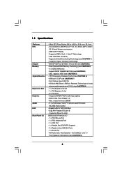
... Overclocking Technology (see CAUTION 4) - Support DDR2 1066/800/667/533 (see CAUTION 1) - CPU Frequency Stepless Control (see CAUTION 7) - ASRock U-COP (see CAUTION 6) - Boot Failure Guard (B.F.G.) - ASRock AM2 Boost: ASRock Patented Technology to boost memory performance up to -Use USB 2.0 Ports - 1 x RJ-45...see CAUTION 2) - Max. Socket AM2 for AMD PhenomTM X4 / X2, Athlon 64FX / 64X2 / X2 / 64 and Sempron processors - Supports Wake-On-LAN ASRock 6CH Premium I /O - Gigabit LAN 10/100/1000 Mb/s - 1.2 Specifications Platform CPU Chipset Memory Hybrid Booster Expansion Slot...
... Overclocking Technology (see CAUTION 4) - Support DDR2 1066/800/667/533 (see CAUTION 1) - CPU Frequency Stepless Control (see CAUTION 7) - ASRock U-COP (see CAUTION 6) - Boot Failure Guard (B.F.G.) - ASRock AM2 Boost: ASRock Patented Technology to boost memory performance up to -Use USB 2.0 Ports - 1 x RJ-45...see CAUTION 2) - Max. Socket AM2 for AMD PhenomTM X4 / X2, Athlon 64FX / 64X2 / X2 / 64 and Sempron processors - Supports Wake-On-LAN ASRock 6CH Premium I /O - Gigabit LAN 10/100/1000 Mb/s - 1.2 Specifications Platform CPU Chipset Memory Hybrid Booster Expansion Slot...
User Manual
Page 10
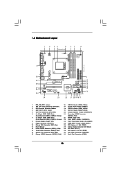
...SOCKET AM2 31 USB 2.0 T: USB2 B: USB3 USB 2.0 T: USB0 B: USB1 Top: RJ-45 IDE1 FSB1GHz DDRII800 FLOPPY1 ATA133 ATXPWR1 Top: REAR SPK Bottom: CTR BASS 30 29 28 27 26 25 Top: LINE IN Center: FRONT Bottom: MIC IN LAN PHY CD1 AUDIO CODEC HDMI_SPDIF1 1 1 HD_AUDIO1 PCIE1 PCI EXPRESS RAID ALiveNF6G-GLAN...Blue) 2 ATX 12V Power Connector (ATX12V1) 17 System Panel Header (PANEL1) 3 CPU Heatsink Retention Module 18 USB 2.0 Header (USB8_9, Blue) 4 AM2 940-Pin CPU Socket 19 USB 2.0 Header (USB4_5, Blue) 5 CPU Fan Connector (CPU_FAN1) 20 Chassis Speaker Header (SPEAKER 1) 6 2 x 240-...
...SOCKET AM2 31 USB 2.0 T: USB2 B: USB3 USB 2.0 T: USB0 B: USB1 Top: RJ-45 IDE1 FSB1GHz DDRII800 FLOPPY1 ATA133 ATXPWR1 Top: REAR SPK Bottom: CTR BASS 30 29 28 27 26 25 Top: LINE IN Center: FRONT Bottom: MIC IN LAN PHY CD1 AUDIO CODEC HDMI_SPDIF1 1 1 HD_AUDIO1 PCIE1 PCI EXPRESS RAID ALiveNF6G-GLAN...Blue) 2 ATX 12V Power Connector (ATX12V1) 17 System Panel Header (PANEL1) 3 CPU Heatsink Retention Module 18 USB 2.0 Header (USB8_9, Blue) 4 AM2 940-Pin CPU Socket 19 USB 2.0 Header (USB4_5, Blue) 5 CPU Fan Connector (CPU_FAN1) 20 Chassis Speaker Header (SPEAKER 1) 6 2 x 240-...

User Manual
Page 13
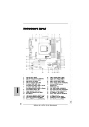
... NOT force the CPU into the socket to dissipate heat. Lever 90° Up CPU Golden Triangle STEP 1: Lift Up The Socket Lever Socket Corner STEP 2 / STEP 3: STEP 4: Match The CPU Golden Triangle Push Down And Lock To The Socket Corner The Socket Lever 2.2 Installation of CPU Fan and Heatsink After you install the CPU into the socket until it is...
... NOT force the CPU into the socket to dissipate heat. Lever 90° Up CPU Golden Triangle STEP 1: Lift Up The Socket Lever Socket Corner STEP 2 / STEP 3: STEP 4: Match The CPU Golden Triangle Push Down And Lock To The Socket Corner The Socket Lever 2.2 Installation of CPU Fan and Heatsink After you install the CPU into the socket until it is...
Quick Installation Guide
Page 2
... Header (USB6_7, Blue) 2 ATX 12V Power Connector (ATX12V1) 17 System Panel Header (PANEL1) 3 CPU Heatsink Retention Module 18 USB 2.0 Header (USB8_9, Blue) 4 AM2 940-Pin CPU Socket 19 USB 2.0 Header (USB4_5, Blue) 5 CPU Fan Connector (CPU_FAN1) 20 Chassis Speaker Header (SPEAKER 1) 6 2 x 240-pin DDR2 DIMM Slots 21... (CHA_FAN1) 30 ATX Power Connector (ATXPWR1) 15 Primary SATAII Connector (SATAII_1, Red) 31 Serial Port Connector (COM1) 2 ASRock ALiveNF6G-GLAN Motherboard Yellow) (SATAII_2, Red) 7 2 x 240-pin DDR2 DIMM Slots 22 NVIDIA Single Chip (Dual Channel B: DDRII_3, DDRII_4;
... Header (USB6_7, Blue) 2 ATX 12V Power Connector (ATX12V1) 17 System Panel Header (PANEL1) 3 CPU Heatsink Retention Module 18 USB 2.0 Header (USB8_9, Blue) 4 AM2 940-Pin CPU Socket 19 USB 2.0 Header (USB4_5, Blue) 5 CPU Fan Connector (CPU_FAN1) 20 Chassis Speaker Header (SPEAKER 1) 6 2 x 240-pin DDR2 DIMM Slots 21... (CHA_FAN1) 30 ATX Power Connector (ATXPWR1) 15 Primary SATAII Connector (SATAII_1, Red) 31 Serial Port Connector (COM1) 2 ASRock ALiveNF6G-GLAN Motherboard Yellow) (SATAII_2, Red) 7 2 x 240-pin DDR2 DIMM Slots 22 NVIDIA Single Chip (Dual Channel B: DDRII_3, DDRII_4;

Quick Installation Guide
Page 5
.../ Front Speaker / Microphone (see CAUTION 2) - NVIDIA® GeForce 6150SE / nForce 430 (see CAUTION 9) English 5 ASRock ALiveNF6G-GLAN Motherboard Boot Failure Guard (B.F.G.) - DX9.0 VGA, Pixel Shader 3.0 - 1.2 Specifications Platform CPU Chipset Memory Hybrid Booster Expansion Slot Graphics Audio LAN Rear Panel I /O - 1 x PS/2 Mouse Port - 1 ... (see CAUTION 8) - 1 x PCI Express x16 slot - 1 x PCI Express x1 slot - 2 x PCI slots - ASRock U-COP (see CAUTION 1) - Socket AM2 for AMD PhenomTM X4 / X2, Athlon 64FX / 64X2 / X2 / 64 and Sempron processors - AMD LIVE!TM Ready ...
.../ Front Speaker / Microphone (see CAUTION 2) - NVIDIA® GeForce 6150SE / nForce 430 (see CAUTION 9) English 5 ASRock ALiveNF6G-GLAN Motherboard Boot Failure Guard (B.F.G.) - DX9.0 VGA, Pixel Shader 3.0 - 1.2 Specifications Platform CPU Chipset Memory Hybrid Booster Expansion Slot Graphics Audio LAN Rear Panel I /O - 1 x PS/2 Mouse Port - 1 ... (see CAUTION 8) - 1 x PCI Express x16 slot - 1 x PCI Express x1 slot - 2 x PCI slots - ASRock U-COP (see CAUTION 1) - Socket AM2 for AMD PhenomTM X4 / X2, Athlon 64FX / 64X2 / X2 / 64 and Sempron processors - AMD LIVE!TM Ready ...

Quick Installation Guide
Page 9
... following precautions before you uninstall any component. DO NOT force the CPU into the socket to the motherboard, peripherals, and/or components. 2. English 9 ASRock ALiveNF6G-GLAN Motherboard Step 3. The lever clicks on the socket while you install motherboard components or change any motherboard settings. 1. Unlock the socket by the edges and do not touch the ICs. 4. When...
... following precautions before you uninstall any component. DO NOT force the CPU into the socket to the motherboard, peripherals, and/or components. 2. English 9 ASRock ALiveNF6G-GLAN Motherboard Step 3. The lever clicks on the socket while you install motherboard components or change any motherboard settings. 1. Unlock the socket by the edges and do not touch the ICs. 4. When...


