
RAID Installation Guide
Page 8
...-bit and Windows Vista / Vista 64-bit, there are different installation procedures. Please enter NVRAIDMAN by using NVIDIAMAN under Windows environment. 2. After you finish the driver installation, you to the OS you install. 2.1 NVIDIA Windows RAID Installation Guide for you can create, delete, or rebuild any RAID array. NVIDIA Windows RAID Installation Guide NVIDIA Windows RAID Installation Guide is an instruction for Windows 2000 / XP / XP 64-bit Users A. Please read this guide carefully and follow the instructions below screen...
...-bit and Windows Vista / Vista 64-bit, there are different installation procedures. Please enter NVRAIDMAN by using NVIDIAMAN under Windows environment. 2. After you finish the driver installation, you to the OS you install. 2.1 NVIDIA Windows RAID Installation Guide for you can create, delete, or rebuild any RAID array. NVIDIA Windows RAID Installation Guide NVIDIA Windows RAID Installation Guide is an instruction for Windows 2000 / XP / XP 64-bit Users A. Please read this guide carefully and follow the instructions below screen...
User Manual
Page 8
... the compatible memory modules. If you implement Dual Channel Memory Technology, make sure to disable this motherboard offers stepless control, it may be GeForce 6150SE / nForce 430 instead of memory modules on the AM2 CPU you install the PC system. 8. While CPU overheat is enabled, it is no such limitation. 6. CAUTION! 1. Although this function for all CPU/DRAM configurations. For audio output, this motherboard supports both stereo and mono modes. ASRock website...
... the compatible memory modules. If you implement Dual Channel Memory Technology, make sure to disable this motherboard offers stepless control, it may be GeForce 6150SE / nForce 430 instead of memory modules on the AM2 CPU you install the PC system. 8. While CPU overheat is enabled, it is no such limitation. 6. CAUTION! 1. Although this function for all CPU/DRAM configurations. For audio output, this motherboard supports both stereo and mono modes. ASRock website...
User Manual
Page 9
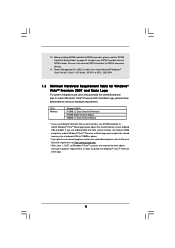
... you use external graphics card on page 24 to adjust your SATAII hard disk drive to 64MB. CPU Memory Sempron 2800+ 512MB x 2 Dual Channel (Premium) 512MB Single Channel (Basic) 256MB x 2 Dual Channel (Basic) * If you plan to use onboard VGA with total system memory size above minimum hardware requirements in order to qualify for Windows® VistaTM Premium 2007 logo. 9 Power Management for USB 2.0 works fine under Microsoft® Windows® VistaTM 64-bit...
... you use external graphics card on page 24 to adjust your SATAII hard disk drive to 64MB. CPU Memory Sempron 2800+ 512MB x 2 Dual Channel (Premium) 512MB Single Channel (Basic) 256MB x 2 Dual Channel (Basic) * If you plan to use onboard VGA with total system memory size above minimum hardware requirements in order to qualify for Windows® VistaTM Premium 2007 logo. 9 Power Management for USB 2.0 works fine under Microsoft® Windows® VistaTM 64-bit...
User Manual
Page 10
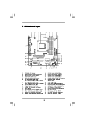
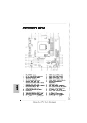
... 940-Pin CPU Socket 19 USB 2.0 Header (USB4_5, Blue) 5 CPU Fan Connector (CPU_FAN1) 20 Chassis Speaker Header (SPEAKER 1) 6 2 x 240-pin DDR2 DIMM Slots 21 Secondary SATAII Connector (Dual Channel A: DDRII_1, DDRII_2; Yellow) (SATAII_2, Red) 7 2 x 240-pin DDR2 DIMM Slots 22 NVIDIA Single Chip (Dual Channel B: DDRII_3, DDRII_4; Orange) 23 Clear CMOS Jumper (CLRCMOS1) 8 Infrared Module Header (IR1) 24 Front Panel Audio Header (HD_AUDIO1) 9 Floppy Connector (FLOPPY1) 25 HDMI_SPDIF Header (HDMI_SPDIF1) 10 Primary IDE Connector (IDE1, Blue) 26 PCI Express x1 Slot (PCIE2) 11 Flash...
... 940-Pin CPU Socket 19 USB 2.0 Header (USB4_5, Blue) 5 CPU Fan Connector (CPU_FAN1) 20 Chassis Speaker Header (SPEAKER 1) 6 2 x 240-pin DDR2 DIMM Slots 21 Secondary SATAII Connector (Dual Channel A: DDRII_1, DDRII_2; Yellow) (SATAII_2, Red) 7 2 x 240-pin DDR2 DIMM Slots 22 NVIDIA Single Chip (Dual Channel B: DDRII_3, DDRII_4; Orange) 23 Clear CMOS Jumper (CLRCMOS1) 8 Infrared Module Header (IR1) 24 Front Panel Audio Header (HD_AUDIO1) 9 Floppy Connector (FLOPPY1) 25 HDMI_SPDIF Header (HDMI_SPDIF1) 10 Primary IDE Connector (IDE1, Blue) 26 PCI Express x1 Slot (PCIE2) 11 Flash...
User Manual
Page 17
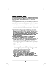
... motherboard. 2.5 Easy Multi Monitor Feature This motherboard supports Multi Monitor upgrade. Connect another D-Sub input monitor cable to enable the function of this monitor". Enter "Share Memory" option to adjust the memory capability to [16MB], [32MB], [64MB], [128MB], or [256MB] to the VGA/D-Sub connector of the system memory. Set the "Screen Resolution" and "Color Quality" as Secondary. C. Connect the D-Sub input monitor cable to PCIE1 (PCIE x16 slot). Install the NVIDIA® PCI Express VGA card to the VGA/D-Sub port...
... motherboard. 2.5 Easy Multi Monitor Feature This motherboard supports Multi Monitor upgrade. Connect another D-Sub input monitor cable to enable the function of this monitor". Enter "Share Memory" option to adjust the memory capability to [16MB], [32MB], [64MB], [128MB], or [256MB] to the VGA/D-Sub connector of the system memory. Set the "Screen Resolution" and "Color Quality" as Secondary. C. Connect the D-Sub input monitor cable to PCIE1 (PCIE x16 slot). Install the NVIDIA® PCI Express VGA card to the VGA/D-Sub port...
User Manual
Page 23
...-digital audio/video specification, which provides SPDIF audio output to HDMI VGA card, allows the system to the same pin definition. Install the HDMI VGA card to the installation guide on the motherboard. Make sure to correctly connect the HDMI_SPDIF cable to the motherboard and the HDMI VGA card according to connect HDMI Digital TV/projector/ LCD devices. For example, this picture shows the wrong example of HDMI VGA card, please refer to the PCI Express Graphics slot on this motherboard. To use HDMI function...
...-digital audio/video specification, which provides SPDIF audio output to HDMI VGA card, allows the system to the same pin definition. Install the HDMI VGA card to the installation guide on the motherboard. Make sure to correctly connect the HDMI_SPDIF cable to the motherboard and the HDMI VGA card according to connect HDMI Digital TV/projector/ LCD devices. For example, this picture shows the wrong example of HDMI VGA card, please refer to the PCI Express Graphics slot on this motherboard. To use HDMI function...

User Manual
Page 24
... hard disk to SATAII mode in advance; Some default setting of different vendors, the jumper pin setting methods may fail to enable SATAII 3.0Gb/s, please remove the jumpers from pin 5 and pin 6. In order to enable SATAII function, please follow the below SATAII hard disk setup guide. SAMSUNG 7531 8642 If pin 3 and pin 4 are just for details: http://www.hitachigst.com/hdd/support/download.htm The above examples are shorted, SATA 1.5Gb/s will be enabled...
... hard disk to SATAII mode in advance; Some default setting of different vendors, the jumper pin setting methods may fail to enable SATAII 3.0Gb/s, please remove the jumpers from pin 5 and pin 6. In order to enable SATAII function, please follow the below SATAII hard disk setup guide. SAMSUNG 7531 8642 If pin 3 and pin 4 are just for details: http://www.hitachigst.com/hdd/support/download.htm The above examples are shorted, SATA 1.5Gb/s will be enabled...
User Manual
Page 29
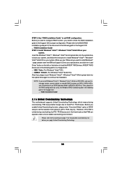
... Support CD: .. \ RAID Installation Guide STEP 4: Install Windows® 2000 / Windows® XP / Windows® XP-64bit OS on your SATA / SATAII HDDs with RAID functions, please follow below steps. STEP 1: Set Up BIOS. Enter BIOS SETUP UTILITY Advanced screen B. The system will start Please insert a floppy diskette into the floppy drive, and press any key. B. Then you install. Select the driver to install according to [RAID]. Set the "SATA Operation Mode" option to format the floppy diskette and copy SATA / SATAII drivers into floppy drive...
... Support CD: .. \ RAID Installation Guide STEP 4: Install Windows® 2000 / Windows® XP / Windows® XP-64bit OS on your SATA / SATAII HDDs with RAID functions, please follow below steps. STEP 1: Set Up BIOS. Enter BIOS SETUP UTILITY Advanced screen B. The system will start Please insert a floppy diskette into the floppy drive, and press any key. B. Then you install. Select the driver to install according to [RAID]. Set the "SATA Operation Mode" option to format the floppy diskette and copy SATA / SATAII drivers into floppy drive...
User Manual
Page 30
... "RAID Installation Guide" to set the selection from [Auto] to [CPU, PCIE, Async.]. Please refer to the BIOS RAID installation guide part of BIOS setup to manage (create, convert, delete, or rebuild) RAID functions on your system. NVIDIA® RAID drivers are in BIOS first. If you install Windows® VistaTM / Windows® VistaTM 64-bit on IDE HDDs and want to set the RAID configuration by using the Windows RAID installation guide in the following path in the Support CD: .. \ RAID Installation Guide 2 . 1 6 Untied Overclocking Technology This motherboard supports...
... "RAID Installation Guide" to set the selection from [Auto] to [CPU, PCIE, Async.]. Please refer to the BIOS RAID installation guide part of BIOS setup to manage (create, convert, delete, or rebuild) RAID functions on your system. NVIDIA® RAID drivers are in BIOS first. If you install Windows® VistaTM / Windows® VistaTM 64-bit on IDE HDDs and want to set the RAID configuration by using the Windows RAID installation guide in the following path in the Support CD: .. \ RAID Installation Guide 2 . 1 6 Untied Overclocking Technology This motherboard supports...
User Manual
Page 40
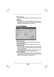
... Configuration BIOS SETUP UTILITY Advanced IDE Configuration OnBoard IDE Controller OnBoard SATA Controller SATA Operation Mode IDE Master IDE Slave SATAII 1 SATAII 2 SATAII 3 SATAII 4 [Enabled] [Enabled] [non-RAID] [Hard Disk] [Not Detected] [Not Detected] [Not Detected] [Not Detected] [Not Detected] ENABLED: enables the integrated IDE Controller. ACPI HPET Table Use this motherboard to power on SATA / SATAII HDDs, please select [RAID]. * If you select [RAID] mode, SATA / SATAII HDDs can be accessed until you plan to use the "IDE Master" as the example in the following instruction...
... Configuration BIOS SETUP UTILITY Advanced IDE Configuration OnBoard IDE Controller OnBoard SATA Controller SATA Operation Mode IDE Master IDE Slave SATAII 1 SATAII 2 SATAII 3 SATAII 4 [Enabled] [Enabled] [non-RAID] [Hard Disk] [Not Detected] [Not Detected] [Not Detected] [Not Detected] [Not Detected] ENABLED: enables the integrated IDE Controller. ACPI HPET Table Use this motherboard to power on SATA / SATAII HDDs, please select [RAID]. * If you select [RAID] mode, SATA / SATAII HDDs can be accessed until you plan to use the "IDE Master" as the example in the following instruction...
User Manual
Page 42
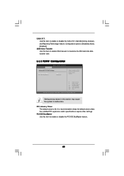
... to enable 32-bit access to enable or disable the S.M.A.R.T. (Self-Monitoring, Analysis, and Reporting Technology) feature. It is 32. Setting wrong values in this item to maximize the IDE hard disk data transfer rate. 3.3.5 PCIPnP Configuration BIOS SETUP UTILITY Advanced Advanced PCI / PnP Settings PCI Latency Timer PCI IDE BusMaster [64] [Enabled] Value in units of PCI clocks for PCI device latency timer register. +F1 F9 F10 ESC Select Screen Select Item Change Option General Help Load Defaults Save...
... to enable 32-bit access to enable or disable the S.M.A.R.T. (Self-Monitoring, Analysis, and Reporting Technology) feature. It is 32. Setting wrong values in this item to maximize the IDE hard disk data transfer rate. 3.3.5 PCIPnP Configuration BIOS SETUP UTILITY Advanced Advanced PCI / PnP Settings PCI Latency Timer PCI IDE BusMaster [64] [Enabled] Value in units of PCI clocks for PCI device latency timer register. +F1 F9 F10 ESC Select Screen Select Item Change Option General Help Load Defaults Save...
User Manual
Page 49
..., locate and double click on a specific item then follow the installation wizard to install it. 4.2.4 Contact Information If you may contact your computer. Because motherboard settings and hardware options vary, use the setup procedures in the Support CD to your CD-ROM drive. Refer to display the menus. 4.2.2 Drivers Menu The Drivers Menu shows the available devices drivers if the system detects the installed devices. Please install the necessary drivers to activate the devices. 4.2.3 Utilities Menu...
..., locate and double click on a specific item then follow the installation wizard to install it. 4.2.4 Contact Information If you may contact your computer. Because motherboard settings and hardware options vary, use the setup procedures in the Support CD to your CD-ROM drive. Refer to display the menus. 4.2.2 Drivers Menu The Drivers Menu shows the available devices drivers if the system detects the installed devices. Please install the necessary drivers to activate the devices. 4.2.3 Utilities Menu...
Quick Installation Guide
Page 2
... 940-Pin CPU Socket 19 USB 2.0 Header (USB4_5, Blue) 5 CPU Fan Connector (CPU_FAN1) 20 Chassis Speaker Header (SPEAKER 1) 6 2 x 240-pin DDR2 DIMM Slots 21 Secondary SATAII Connector (Dual Channel A: DDRII_1, DDRII_2; Yellow) (SATAII_2, Red) 7 2 x 240-pin DDR2 DIMM Slots 22 NVIDIA Single Chip (Dual Channel B: DDRII_3, DDRII_4; Orange) 23 Clear CMOS Jumper (CLRCMOS1) 8 Infrared Module Header (IR1) 24 Front Panel Audio Header (HD_AUDIO1) 9 Floppy Connector (FLOPPY1) 25 HDMI_SPDIF Header (HDMI_SPDIF1) 10 Primary IDE Connector (IDE1, Blue) 26 PCI Express x1 Slot (PCIE2) 11 Flash...
... 940-Pin CPU Socket 19 USB 2.0 Header (USB4_5, Blue) 5 CPU Fan Connector (CPU_FAN1) 20 Chassis Speaker Header (SPEAKER 1) 6 2 x 240-pin DDR2 DIMM Slots 21 Secondary SATAII Connector (Dual Channel A: DDRII_1, DDRII_2; Yellow) (SATAII_2, Red) 7 2 x 240-pin DDR2 DIMM Slots 22 NVIDIA Single Chip (Dual Channel B: DDRII_3, DDRII_4; Orange) 23 Clear CMOS Jumper (CLRCMOS1) 8 Infrared Module Header (IR1) 24 Front Panel Audio Header (HD_AUDIO1) 9 Floppy Connector (FLOPPY1) 25 HDMI_SPDIF Header (HDMI_SPDIF1) 10 Primary IDE Connector (IDE1, Blue) 26 PCI Express x1 Slot (PCIE2) 11 Flash...

Quick Installation Guide
Page 7
... on this motherboard offers stepless control, it is not recommended to your system. If you implement Dual Channel Memory Technology, make sure to the memory support list on our website for proper connection. 7 ASRock ALiveNF6G-GLAN Motherboard English Although this motherboard, please refer to read "Untied Overclocking Technology" on page 3 for the compatible memory modules. Enabling this motherboard supports both stereo and mono modes. For audio output, this function in device name under Windows® XP...
... on this motherboard offers stepless control, it is not recommended to your system. If you implement Dual Channel Memory Technology, make sure to the memory support list on our website for proper connection. 7 ASRock ALiveNF6G-GLAN Motherboard English Although this motherboard, please refer to read "Untied Overclocking Technology" on page 3 for the compatible memory modules. Enabling this motherboard supports both stereo and mono modes. For audio output, this function in device name under Windows® XP...

Quick Installation Guide
Page 8
... 8 ASRock ALiveNF6G-GLAN Motherboard CPU Memory Sempron 2800+ 512MB x 2 Dual Channel (Premium) 512MB Single Channel (Basic) 256MB x 2 Dual Channel (Basic) * If you use onboard VGA with total system memory size above 512MB and plan to submit Windows® VistaTM Premium or Basic logo, please adjust the shared memory size of onboard VGA to SATAII mode. If you use external graphics card on page 20 to adjust your SATAII hard disk drive to 64MB. You can also connect SATA hard disk to submit Windows...
... 8 ASRock ALiveNF6G-GLAN Motherboard CPU Memory Sempron 2800+ 512MB x 2 Dual Channel (Premium) 512MB Single Channel (Basic) 256MB x 2 Dual Channel (Basic) * If you use onboard VGA with total system memory size above 512MB and plan to submit Windows® VistaTM Premium or Basic logo, please adjust the shared memory size of onboard VGA to SATAII mode. If you use external graphics card on page 20 to adjust your SATAII hard disk drive to 64MB. You can also connect SATA hard disk to submit Windows...

Quick Installation Guide
Page 17
.... Enter BIOS Setup Utility. For Windows® VistaTM / VistaTM 64-bit OS: Click the right-top "Folder" icon , choose "Disable front panel jack detection", and save the change by clicking "OK". CPU Fan Connector (4-pin CPU_FAN1) (see p.2 No. 20) Please connect the chassis speaker to the ground pin. E. Enter Advanced Settings, and then select Chipset Configuration. Enter Windows system. Click the icon on this motherboard provides 4-Pin CPU fan (Quiet Fan) support, the 3-Pin CPU fan still can work successfully even without the fan speed control...
.... Enter BIOS Setup Utility. For Windows® VistaTM / VistaTM 64-bit OS: Click the right-top "Folder" icon , choose "Disable front panel jack detection", and save the change by clicking "OK". CPU Fan Connector (4-pin CPU_FAN1) (see p.2 No. 20) Please connect the chassis speaker to the ground pin. E. Enter Advanced Settings, and then select Chipset Configuration. Enter Windows system. Click the icon on this motherboard provides 4-Pin CPU fan (Quiet Fan) support, the 3-Pin CPU fan still can work successfully even without the fan speed control...
Quick Installation Guide
Page 19
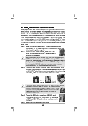
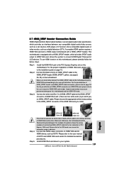
... a set-top box, DVD player, A/V receiver and a compatible digital audio or video monitor, such as HDTV. Step 2. Otherwise, the motherboard and the VGA card may cause permanent damage to this motherboard. Connect the black end (A) of HDMI_SPDIF cable to your system. 19 ASRock ALiveNF6G-GLAN Motherboard Step 3. 2.7 HDMI_SPDIF Header Connection Guide HDMI (High-Definition Multi-media Interface) is equipped with a HDMI_SPDIF header. This motherboard is an all-digital audio/video specification, which provides SPDIF audio output to HDMI VGA card, allows...
... a set-top box, DVD player, A/V receiver and a compatible digital audio or video monitor, such as HDTV. Step 2. Otherwise, the motherboard and the VGA card may cause permanent damage to this motherboard. Connect the black end (A) of HDMI_SPDIF cable to your system. 19 ASRock ALiveNF6G-GLAN Motherboard Step 3. 2.7 HDMI_SPDIF Header Connection Guide HDMI (High-Definition Multi-media Interface) is equipped with a HDMI_SPDIF header. This motherboard is an all-digital audio/video specification, which provides SPDIF audio output to HDMI VGA card, allows...

Quick Installation Guide
Page 22
... drivers you install can be auto-detected and listed on your Windows® 2000 optical disk is no need for you don't have to install Windows® 2000, Windows® XP, Windows® XP 64-bit, Windows® VistaTM or Windows® VistaTM 64-bit OS on the screen, "Generate Serial ATA driver diskette [YN]?", press . 22 ASRock ALiveNF6G-GLAN Motherboard Insert the ASRock Support CD into your optical drive to your SATA / SATAII HDDs with RAID...
... drivers you install can be auto-detected and listed on your Windows® 2000 optical disk is no need for you don't have to install Windows® 2000, Windows® XP, Windows® XP 64-bit, Windows® VistaTM or Windows® VistaTM 64-bit OS on the screen, "Generate Serial ATA driver diskette [YN]?", press . 22 ASRock ALiveNF6G-GLAN Motherboard Insert the ASRock Support CD into your optical drive to your SATA / SATAII HDDs with RAID...

Quick Installation Guide
Page 23
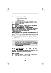
...-bit on IDE HDDs and want to [RAID]. If you can start to the BIOS RAID installation guide in the following path in the Support CD for proper configuration. Enter BIOS SETUP UTILITY Advanced screen B. The system will start Please insert a floppy diskette into the floppy drive, and press any key to check the RAID installation guide in the Support CD: .. \ RAID Installation Guide 2.13.2 Installing Windows® VistaTM / VistaTM 64-bit With RAID Functions If you install. B. NOTE. A. Set the "SATA Operation Mode" option to set RAID configuration. STEP 3: Use "RAID...
...-bit on IDE HDDs and want to [RAID]. If you can start to the BIOS RAID installation guide in the following path in the Support CD for proper configuration. Enter BIOS SETUP UTILITY Advanced screen B. The system will start Please insert a floppy diskette into the floppy drive, and press any key to check the RAID installation guide in the Support CD: .. \ RAID Installation Guide 2.13.2 Installing Windows® VistaTM / VistaTM 64-bit With RAID Functions If you install. B. NOTE. A. Set the "SATA Operation Mode" option to set RAID configuration. STEP 3: Use "RAID...

Quick Installation Guide
Page 25
.... It is enabled in the Support CD. 4. For the detailed information about BIOS Setup, please refer to display the menus. 25 ASRock ALiveNF6G-GLAN Motherboard English 3. otherwise, POST continues with the motherboard contains necessary drivers and useful utilities that came with its various sub-menus and to enter BIOS Setup after POST, please restart the system by pressing + + , or pressing the reset button on the system chassis. To begin using the Support CD...
.... It is enabled in the Support CD. 4. For the detailed information about BIOS Setup, please refer to display the menus. 25 ASRock ALiveNF6G-GLAN Motherboard English 3. otherwise, POST continues with the motherboard contains necessary drivers and useful utilities that came with its various sub-menus and to enter BIOS Setup after POST, please restart the system by pressing + + , or pressing the reset button on the system chassis. To begin using the Support CD...


