User Manual
Page 5
... change without further notice. In this manual, chapter 1 and 2 contain introduction of the Support CD. ASRock website http://www.asrock.com 1.1 Package Contents 1 x ASRock ALiveNF5-eSATA2+ Motherboard (ATX Form Factor: 12.0-in x 8.0-in, 30.5 cm x 20.3 cm) 1 x ASRock ALiveNF5-eSATA2+ Quick Installation Guide 1 x ASRock ALiveNF5-eSATA2+ Support CD 1 x Ultra ATA 66/100/133 IDE Ribbon Cable (80-conductor) 1 x 3.5-in Floppy Drive...
... change without further notice. In this manual, chapter 1 and 2 contain introduction of the Support CD. ASRock website http://www.asrock.com 1.1 Package Contents 1 x ASRock ALiveNF5-eSATA2+ Motherboard (ATX Form Factor: 12.0-in x 8.0-in, 30.5 cm x 20.3 cm) 1 x ASRock ALiveNF5-eSATA2+ Quick Installation Guide 1 x ASRock ALiveNF5-eSATA2+ Support CD 1 x Ultra ATA 66/100/133 IDE Ribbon Cable (80-conductor) 1 x 3.5-in Floppy Drive...

Quick Installation Guide
Page 1
...regulations in Perchlorate Best Management Practices (BMP) regulations passed by the California Legislature. With respect to the contents of this guide, ASRock does not provide warranty of any kind, either expressed or implied, including but not limited to the following two conditions: (1) ...the implied warranties or conditions of merchantability or fitness for informational use only and subject to infringe. All rights reserved. 1 ASRock ALiveNF5-eSATA2+ Motherboard English Products and corporate names appearing in this guide may or may not be registered trademarks or copyrights of their ...
...regulations in Perchlorate Best Management Practices (BMP) regulations passed by the California Legislature. With respect to the contents of this guide, ASRock does not provide warranty of any kind, either expressed or implied, including but not limited to the following two conditions: (1) ...the implied warranties or conditions of merchantability or fitness for informational use only and subject to infringe. All rights reserved. 1 ASRock ALiveNF5-eSATA2+ Motherboard English Products and corporate names appearing in this guide may or may not be registered trademarks or copyrights of their ...
Quick Installation Guide
Page 2
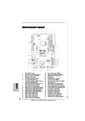
... Connector (ATXPWR1) 16 USB 2.0 Header (USB4_5, Blue) 36 eSATAII Connector (eSATAII_TOP) 17 USB 2.0 Header (USB2_3, Blue) 37 eSATAII Connector (eSATAII_BOTTOM) 18 Chassis Fan Connector (CHA_FAN1) 2 ASRock ALiveNF5-eSATA2+ Motherboard Motherboard Layout English 1 PS2_USB_PW1 Jumper 19 System Panel Header (PANEL1) 2 ATX 12V Power Connector (ATX12V1) 20 Chassis Speaker Header (SPEAKER 1) 3 CPU Fan Connector (CPU_FAN1...
... Connector (ATXPWR1) 16 USB 2.0 Header (USB4_5, Blue) 36 eSATAII Connector (eSATAII_TOP) 17 USB 2.0 Header (USB2_3, Blue) 37 eSATAII Connector (eSATAII_BOTTOM) 18 Chassis Fan Connector (CHA_FAN1) 2 ASRock ALiveNF5-eSATA2+ Motherboard Motherboard Layout English 1 PS2_USB_PW1 Jumper 19 System Panel Header (PANEL1) 2 ATX 12V Power Connector (ATX12V1) 20 Chassis Speaker Header (SPEAKER 1) 3 CPU Fan Connector (CPU_FAN1...
Quick Installation Guide
Page 3
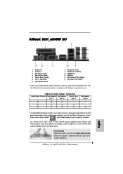
...connection details in accordance with one USB+1394 bracket, which can support 2 additional USB 2.0 ports and 1 IEEE 1394 port. 3 ASRock ALiveNF5-eSATA2+ Motherboard English Choose "2CH", "4CH", "6CH", or "8CH" and then you use Rear Speaker, Central/Bass, and Front ... enable Multi-Streaming function, you need to connect a front panel audio cable to use 2-channel speaker, please connect the speaker's plug into "Front Speaker Jack". ASRock 8CH_eSATAII I/O 1 Parallel Port 2 RJ-45 Port 3 Side Speaker (Gray) 4 Rear Speaker (Black) 5 Central / Bass (Orange) 6 Line In (Light Blue) *7...
...connection details in accordance with one USB+1394 bracket, which can support 2 additional USB 2.0 ports and 1 IEEE 1394 port. 3 ASRock ALiveNF5-eSATA2+ Motherboard English Choose "2CH", "4CH", "6CH", or "8CH" and then you use Rear Speaker, Central/Bass, and Front ... enable Multi-Streaming function, you need to connect a front panel audio cable to use 2-channel speaker, please connect the speaker's plug into "Front Speaker Jack". ASRock 8CH_eSATAII I/O 1 Parallel Port 2 RJ-45 Port 3 Side Speaker (Gray) 4 Rear Speaker (Black) 5 Central / Bass (Orange) 6 Line In (Light Blue) *7...
Quick Installation Guide
Page 4
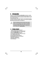
... the latest VGA cards and CPU support lists on ASRock website without notice. Introduction Thank you for purchasing ASRock ALiveNF5-eSATA2+ motherboard, a reliable motherboard produced under ASRock's consistently stringent quality control. In case any modifications of... of the motherboard and step-bystep installation guide. ASRock website http://www.asrock.com 1.1 Package Contents 1 x ASRock ALiveNF5-eSATA2+ Motherboard (ATX Form Factor: 12.0-in x 8.0-in, 30.5 cm x 20.3 cm) 1 x ASRock ALiveNF5-eSATA2+ Quick Installation Guide 1 x ASRock ALiveNF5-eSATA2+ Support CD 1 x Ultra ATA 66/100/...
... the latest VGA cards and CPU support lists on ASRock website without notice. Introduction Thank you for purchasing ASRock ALiveNF5-eSATA2+ motherboard, a reliable motherboard produced under ASRock's consistently stringent quality control. In case any modifications of... of the motherboard and step-bystep installation guide. ASRock website http://www.asrock.com 1.1 Package Contents 1 x ASRock ALiveNF5-eSATA2+ Motherboard (ATX Form Factor: 12.0-in x 8.0-in, 30.5 cm x 20.3 cm) 1 x ASRock ALiveNF5-eSATA2+ Quick Installation Guide 1 x ASRock ALiveNF5-eSATA2+ Support CD 1 x Ultra ATA 66/100/...
Quick Installation Guide
Page 5
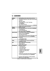
... Mb/s - ATX Form Factor: 12.0-in x 8.0-in /Front Speaker/Microphone (see CAUTION 8) Free Bundle: USB+1394 bracket, providing 2 additional USB 2.0 ports and 1 IEEE 1394 port 5 ASRock ALiveNF5-eSATA2+ Motherboard English NVIDIA® nForce 520 - Dual Channel DDRII Memory Technology (see CAUTION 1) - 1.2 Specifications Platform CPU Chipset Memory Hybrid Booster Expansion Slot Audio LAN Rear...
... Mb/s - ATX Form Factor: 12.0-in x 8.0-in /Front Speaker/Microphone (see CAUTION 8) Free Bundle: USB+1394 bracket, providing 2 additional USB 2.0 ports and 1 IEEE 1394 port 5 ASRock ALiveNF5-eSATA2+ Motherboard English NVIDIA® nForce 520 - Dual Channel DDRII Memory Technology (see CAUTION 1) - 1.2 Specifications Platform CPU Chipset Memory Hybrid Booster Expansion Slot Audio LAN Rear...
Quick Installation Guide
Page 6
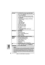
... header - 2 x IEEE 1394 headers - It should be done at your system. CPU Ambient Temperature Sensing - We are not responsible for possible damage caused by overclocking. 6 ASRock ALiveNF5-eSATA2+ Motherboard Connector BIOS Feature Support CD Hardware Monitor OS Certifications - 4 x SATAII 3.0Gb/s connectors, support RAID (RAID 0, RAID 1, RAID 0+1, JBOD, RAID 5), NCQ, AHCI and "Hot Plug...
... header - 2 x IEEE 1394 headers - It should be done at your system. CPU Ambient Temperature Sensing - We are not responsible for possible damage caused by overclocking. 6 ASRock ALiveNF5-eSATA2+ Motherboard Connector BIOS Feature Support CD Hardware Monitor OS Certifications - 4 x SATAII 3.0Gb/s connectors, support RAID (RAID 0, RAID 1, RAID 0+1, JBOD, RAID 5), NCQ, AHCI and "Hot Plug...
Quick Installation Guide
Page 7
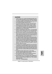
.... 2. This motherboard supports Untied Overclocking Technology. Frequencies other than 4GB for the reservation for proper installation. 4. This motherboard supports ASRock AM2 Boost overclocking technology. However, we will update it is not recommended to our website in the future. If your system ... / XP 64-bit / XP SP1 or SP2 / 2000 SP4. 12. See APPENDIX on page 3 for details. 3. ASRock website http://www.asrock.com 7 ASRock ALiveNF5-eSATA2+ Motherboard English Please check the table on page 54 of memory modules on page 32 for proper connection. 9. If you install...
.... 2. This motherboard supports Untied Overclocking Technology. Frequencies other than 4GB for the reservation for proper installation. 4. This motherboard supports ASRock AM2 Boost overclocking technology. However, we will update it is not recommended to our website in the future. If your system ... / XP 64-bit / XP SP1 or SP2 / 2000 SP4. 12. See APPENDIX on page 3 for details. 3. ASRock website http://www.asrock.com 7 ASRock ALiveNF5-eSATA2+ Motherboard English Please check the table on page 54 of memory modules on page 32 for proper connection. 9. If you install...

Quick Installation Guide
Page 8
... requirements in order to submit Windows® VistaTM Premium 2007 and Basic logo, please follow below table for Windows® VistaTM Premium 2007 logo. English 8 ASRock ALiveNF5-eSATA2+ Motherboard
... requirements in order to submit Windows® VistaTM Premium 2007 and Basic logo, please follow below table for Windows® VistaTM Premium 2007 logo. English 8 ASRock ALiveNF5-eSATA2+ Motherboard

Quick Installation Guide
Page 9
... motherboard directly on a grounded antistatic pad or in , 30.5 cm x 20.3 cm) motherboard. Hold components by the edges and do so may damage the motherboard. 9 ASRock ALiveNF5-eSATA2+ Motherboard English Whenever you uninstall any component, ensure that the motherboard fits into the screw holes to secure the motherboard to the motherboard, peripherals, and...
... motherboard directly on a grounded antistatic pad or in , 30.5 cm x 20.3 cm) motherboard. Hold components by the edges and do so may damage the motherboard. 9 ASRock ALiveNF5-eSATA2+ Motherboard English Whenever you uninstall any component, ensure that the motherboard fits into the screw holes to secure the motherboard to the motherboard, peripherals, and...
Quick Installation Guide
Page 10
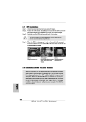
... also need to spray thermal grease between the CPU and the heatsink to the instruction manuals of the CPU fan and the heatsink. English 10 ASRock ALiveNF5-eSATA2+ Motherboard Step 3. Carefully insert the CPU into the socket to dissipate heat. Step 4. When the CPU is in place. DO NOT force the CPU into...
... also need to spray thermal grease between the CPU and the heatsink to the instruction manuals of the CPU fan and the heatsink. English 10 ASRock ALiveNF5-eSATA2+ Motherboard Step 3. Carefully insert the CPU into the socket to dissipate heat. Step 4. When the CPU is in place. DO NOT force the CPU into...
Quick Installation Guide
Page 11
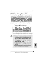
... the DDRII DIMM slots on this motherboard and DIMM may refer to install identical DDRII DIMM pair in all four slots. Yellow slots; English 11 ASRock ALiveNF5-eSATA2+ Motherboard If a pair of memory modules is NOT installed in the same Dual Channel, for optimal compatibility and reliability, it is not allowed to activate...
... the DDRII DIMM slots on this motherboard and DIMM may refer to install identical DDRII DIMM pair in all four slots. Yellow slots; English 11 ASRock ALiveNF5-eSATA2+ Motherboard If a pair of memory modules is NOT installed in the same Dual Channel, for optimal compatibility and reliability, it is not allowed to activate...

Quick Installation Guide
Page 12
... that the notch on the DIMM matches the break on the slot. The DIMM only fits in place and the DIMM is properly seated. 12 ASRock ALiveNF5-eSATA2+ Motherboard English Unlock a DIMM slot by pressing the retaining clips outward. It will cause permanent damage to disconnect power supply before adding or removing DIMMs...
... that the notch on the DIMM matches the break on the slot. The DIMM only fits in place and the DIMM is properly seated. 12 ASRock ALiveNF5-eSATA2+ Motherboard English Unlock a DIMM slot by pressing the retaining clips outward. It will cause permanent damage to disconnect power supply before adding or removing DIMMs...
Quick Installation Guide
Page 13
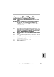
... PCI Express cards with screws. Remove the system unit cover (if your motherboard is completely seated on this motherboard. Step 3. Replace the system cover. 13 ASRock ALiveNF5-eSATA2+ Motherboard English Step 4. Step 2. Align the card connector with x1 lane width cards, such as Gigabit LAN card, SATA2 card, etc.
... PCI Express cards with screws. Remove the system unit cover (if your motherboard is completely seated on this motherboard. Step 3. Replace the system cover. 13 ASRock ALiveNF5-eSATA2+ Motherboard English Step 4. Step 2. Align the card connector with x1 lane width cards, such as Gigabit LAN card, SATA2 card, etc.

Quick Installation Guide
Page 14
..., use a jumper cap to clear the data in CMOS includes system setup information such as system password, date, time, and system setup parameters. English 14 ASRock ALiveNF5-eSATA2+ Motherboard However, please do the clear-CMOS action. To clear and reset the system parameters to clear the CMOS when you just finish updating the...
..., use a jumper cap to clear the data in CMOS includes system setup information such as system password, date, time, and system setup parameters. English 14 ASRock ALiveNF5-eSATA2+ Motherboard However, please do the clear-CMOS action. To clear and reset the system parameters to clear the CMOS when you just finish updating the...
Quick Installation Guide
Page 15
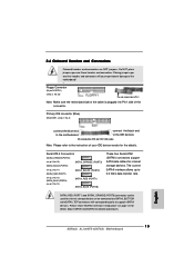
.... SATAII_RED (PORT1) and SATAII_ORANGE (PORT3) connectors can be connected to eSATAII_BOTTOM and eSATAII_TOP connectors with corresponding color to the instruction of the connector. English 15 ASRock ALiveNF5-eSATA2+ Motherboard Primary IDE connector (Blue) (39-pin IDE1, see p.2, No. 23) the red-striped side to 3.0 Gb/s data transfer rate. Please read "eSATAII Interface Introduction...
.... SATAII_RED (PORT1) and SATAII_ORANGE (PORT3) connectors can be connected to eSATAII_BOTTOM and eSATAII_TOP connectors with corresponding color to the instruction of the connector. English 15 ASRock ALiveNF5-eSATA2+ Motherboard Primary IDE connector (Blue) (39-pin IDE1, see p.2, No. 23) the red-striped side to 3.0 Gb/s data transfer rate. Please read "eSATAII Interface Introduction...
Quick Installation Guide
Page 16
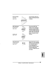
... SATA / SATAII hard disk or the SATAII connector on the motherboard. eSATAII_TOP eSATAII_BOTTOM eSATA II Connectors (eSATAII_TOP: see p.2, No. 36) (eSATAII_BOTTOM: see p.2 No. 16) 16 ASRock ALiveNF5-eSATA2+ Motherboard You can support two USB 2.0 ports. English (9-pin USB4_5) (see p.2, No. 37) Serial ATA (SATA) Data Cable (Optional) Serial ATA (SATA) Power Cable (Optional...
... SATA / SATAII hard disk or the SATAII connector on the motherboard. eSATAII_TOP eSATAII_BOTTOM eSATA II Connectors (eSATAII_TOP: see p.2, No. 36) (eSATAII_BOTTOM: see p.2 No. 16) 16 ASRock ALiveNF5-eSATA2+ Motherboard You can support two USB 2.0 ports. English (9-pin USB4_5) (see p.2, No. 37) Serial ATA (SATA) Data Cable (Optional) Serial ATA (SATA) Power Cable (Optional...
Quick Installation Guide
Page 17
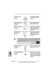
... connection and control of audio devices. 1. Click "Audio I/O", select "Connector Settings" , choose "Disable front panel jack detection", and save the change by clicking "OK". 17 ASRock ALiveNF5-eSATA2+ Motherboard English This is an interface for AC'97 audio panel. Enter Windows system. B. E. (9-pin USB2_3) (see p.2 No. 17) Infrared Module Header (5-pin IR1) (see...
... connection and control of audio devices. 1. Click "Audio I/O", select "Connector Settings" , choose "Disable front panel jack detection", and save the change by clicking "OK". 17 ASRock ALiveNF5-eSATA2+ Motherboard English This is an interface for AC'97 audio panel. Enter Windows system. B. E. (9-pin USB2_3) (see p.2 No. 17) Infrared Module Header (5-pin IR1) (see...
Quick Installation Guide
Page 18
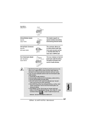
Please connect a chassis fan cable to this connector and match the black wire to the ground pin. English 18 ASRock ALiveNF5-eSATA2+ Motherboard CPU Fan Connector (4-pin CPU_FAN1) (see p.2, No. 3) 1 2 3 4 Please connect the CPU fan cable to this connector and match the black wire to the ground ...
Please connect a chassis fan cable to this connector and match the black wire to the ground pin. English 18 ASRock ALiveNF5-eSATA2+ Motherboard CPU Fan Connector (4-pin CPU_FAN1) (see p.2, No. 3) 1 2 3 4 Please connect the CPU fan cable to this connector and match the black wire to the ground ...
Quick Installation Guide
Page 19
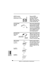
... cable to this header. HDMI_SPDIF Header HDMI_SPDIF header, providing (3-pin HDMI_SPDIF1) SPDIF audio output to con nect HDMI Digital TV/ projector/LCD devices. English 19 ASRock ALiveNF5-eSATA2+ Motherboard IEEE 1394 Headers (9-pin FRONT_1394) (see p.2, No. 30) (9-pin BACK_1394) (see p.2, No. 27) card, allows the system to HDMI VGA i (see p.2, No. 29) There...
... cable to this header. HDMI_SPDIF Header HDMI_SPDIF header, providing (3-pin HDMI_SPDIF1) SPDIF audio output to con nect HDMI Digital TV/ projector/LCD devices. English 19 ASRock ALiveNF5-eSATA2+ Motherboard IEEE 1394 Headers (9-pin FRONT_1394) (see p.2, No. 30) (9-pin BACK_1394) (see p.2, No. 27) card, allows the system to HDMI VGA i (see p.2, No. 29) There...


