
User Manual
Page 3
... Guide 15 2.6 Jumpers Setup 17 2.7 Onboard Headers and Connectors 18 2.8 Serial ATA (SATA) / Serial ATA2 (SATA2) Hard Disks Installation 21 2.9 Hot Plug and Hot Swap Functions for SATA / SATA2 HDDs 21 2.10 SATA / SATA2 HDD Hot Plug Feature and Operation Guide 22 2.11 Driver Installation Guide 24 2.12 Installing Windows® 7 on SATA / SATAII HDDs ........ 24 3 UEFI SETUP UTILITY 25 3.1 Introduction 25 3.1.1 UEFI Menu Bar 25 3.1.2 Navigation Keys 26 3.2 Main Screen 26 3.3 Advanced Screen 27 3.3.1 CPU Configuration 28 3.3.2 Chipset Configuration 29 3.3.3 Storage...
... Guide 15 2.6 Jumpers Setup 17 2.7 Onboard Headers and Connectors 18 2.8 Serial ATA (SATA) / Serial ATA2 (SATA2) Hard Disks Installation 21 2.9 Hot Plug and Hot Swap Functions for SATA / SATA2 HDDs 21 2.10 SATA / SATA2 HDD Hot Plug Feature and Operation Guide 22 2.11 Driver Installation Guide 24 2.12 Installing Windows® 7 on SATA / SATAII HDDs ........ 24 3 UEFI SETUP UTILITY 25 3.1 Introduction 25 3.1.1 UEFI Menu Bar 25 3.1.2 Navigation Keys 26 3.2 Main Screen 26 3.3 Advanced Screen 27 3.3.1 CPU Configuration 28 3.3.2 Chipset Configuration 29 3.3.3 Storage...
User Manual
Page 7
ACPI 1.1 Compliance Wake Up Events - ASRock SmartView (see CAUTION 6) - ASRock XFast LAN (see CAUTION 4) - ASRock Crashless BIOS (see CAUTION 9) - Boot Failure Guard (B.F.G.) Hardware - CPU Temperature Sensing Monitor - We are not responsible for possible damage caused by overclocking. 7 Supports "Plug and Play" - Supports jumperfree - CPU Frequency Stepless Control (see CAUTION 8) - Drivers, Utilities, AntiVirus Software (Trial Version), CyberLink MediaEspresso 6.5 Trial, ASRock MAGIX Multimedia Suite - ASRock XFast USB (see CAUTION 2) - FCC, ...
ACPI 1.1 Compliance Wake Up Events - ASRock SmartView (see CAUTION 6) - ASRock XFast LAN (see CAUTION 4) - ASRock Crashless BIOS (see CAUTION 9) - Boot Failure Guard (B.F.G.) Hardware - CPU Temperature Sensing Monitor - We are not responsible for possible damage caused by overclocking. 7 Supports "Plug and Play" - Supports jumperfree - CPU Frequency Stepless Control (see CAUTION 8) - Drivers, Utilities, AntiVirus Software (Trial Version), CyberLink MediaEspresso 6.5 Trial, ASRock MAGIX Multimedia Suite - ASRock XFast USB (see CAUTION 2) - FCC, ...
User Manual
Page 8
... PC enters into the BIOS setup menu to RAM (S3), hibernation mode (S4) or power off (S5). Just launch this utility, you to quickly charge many Apple devices simultaneously and even supports continuous charging when your USB flash drive, floppy disk or hard drive, then you can press the key during the POST or the key to enter into Standby mode (S1), Suspend to access ASRock Instant Flash. With APP Charger driver installed...
... PC enters into the BIOS setup menu to RAM (S3), hibernation mode (S4) or power off (S5). Just launch this utility, you to quickly charge many Apple devices simultaneously and even supports continuous charging when your USB flash drive, floppy disk or hard drive, then you can press the key during the POST or the key to enter into Standby mode (S1), Suspend to access ASRock Instant Flash. With APP Charger driver installed...
User Manual
Page 18
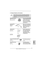
... USB 2.0 ports. Serial ATA (SATA) Data Cable (Optional) Either end of the motherboard! Placing jumper caps over these headers and connectors. USB 2.0 Headers (9-pin USB4_5) (see p.10 No. 13) (9-pin USB6_7) (see p.10 No. 10) 1 GND IRTX IRRX ATX+5VSB This header can be connected to the SATA / SATA2 hard disk or the SATA2 connector on this motherboard. Infrared Module Header (5-pin IR1) (see p.10, No. 6) SATAII_1 SATAII_2 These two Serial ATA2 (SATA2) connectors support SATA data cables for internal storage devices. 2.7 Onboard Headers...
... USB 2.0 ports. Serial ATA (SATA) Data Cable (Optional) Either end of the motherboard! Placing jumper caps over these headers and connectors. USB 2.0 Headers (9-pin USB4_5) (see p.10 No. 13) (9-pin USB6_7) (see p.10 No. 10) 1 GND IRTX IRRX ATX+5VSB This header can be connected to the SATA / SATA2 hard disk or the SATA2 connector on this motherboard. Infrared Module Header (5-pin IR1) (see p.10, No. 6) SATAII_1 SATAII_2 These two Serial ATA2 (SATA2) connectors support SATA data cables for internal storage devices. 2.7 Onboard Headers...
User Manual
Page 20
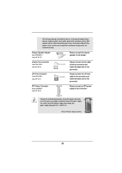
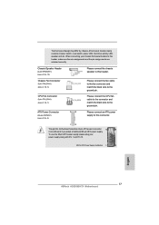
... 24 Please connect the chassis speaker to this header, make sure the wire assignments and the pin assign-ments are matched correctly. To use the 20-pin ATX power supply, please plug your chassis front panel module to this motherboard provides 24-pin ATX power connector, 12 24 it can still work if you adopt a traditional 20-pin ATX power supply. A front panel module mainly consists of power switch, reset switch, power LED, hard drive activity LED, speaker and etc. Please connect the fan cable to the fan connector and match...
... 24 Please connect the chassis speaker to this header, make sure the wire assignments and the pin assign-ments are matched correctly. To use the 20-pin ATX power supply, please plug your chassis front panel module to this motherboard provides 24-pin ATX power connector, 12 24 it can still work if you adopt a traditional 20-pin ATX power supply. A front panel module mainly consists of power switch, reset switch, power LED, hard drive activity LED, speaker and etc. Please connect the fan cable to the fan connector and match...

User Manual
Page 24
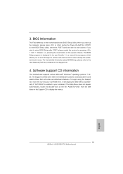
.... Set the option "SATA Mode" to [AHCI]. Using SATA / SATAII HDDs without NCQ function STEP 1: Set up UEFI. Storage Configuration. 24 A. Enter UEFI SETUP UTILITY Advanced screen B. Using SATA / SATAII HDDs with NCQ function STEP 1: Set up UEFI. Enter UEFI SETUP UTILITY Advanced screen B. A. 2.11 Driver Installation Guide To install the drivers to your system, please insert the support CD to your system. Please follow below steps. STEP 2: Install Windows® 7 OS on your system. Therefore, the drivers you install can be auto-detected and listed...
.... Set the option "SATA Mode" to [AHCI]. Using SATA / SATAII HDDs without NCQ function STEP 1: Set up UEFI. Storage Configuration. 24 A. Enter UEFI SETUP UTILITY Advanced screen B. Using SATA / SATAII HDDs with NCQ function STEP 1: Set up UEFI. Enter UEFI SETUP UTILITY Advanced screen B. A. 2.11 Driver Installation Guide To install the drivers to your system, please insert the support CD to your system. Please follow below steps. STEP 2: Install Windows® 7 OS on your system. Therefore, the drivers you install can be auto-detected and listed...

User Manual
Page 25
... restart by pressing the reset button on . You can also use the UEFI SETUP UTILITY to enter the UEFI SETUP UTILITY, otherwise, POST will continue with the following selections: Main To set up the system time/date information OC Tweaker To set up overclocking features Advanced To set up the advanced UEFI features H/W Monitor To display current hardware status Boot To set up the default system device to locate and load the Operating System Security...
... restart by pressing the reset button on . You can also use the UEFI SETUP UTILITY to enter the UEFI SETUP UTILITY, otherwise, POST will continue with the following selections: Main To set up the system time/date information OC Tweaker To set up overclocking features Advanced To set up the advanced UEFI features H/W Monitor To display current hardware status Boot To set up the default system device to locate and load the Operating System Security...

User Manual
Page 29
... set this option to [Enabled] if you plan to use this motherboard to enable or disable ACPI HPET Table. Restore on . The keyboard LED will be turned off when the power recovers. If you to boot up when the power recovers. If [Power On] is [Enabled]. Onboard LAN This allows you select [Auto], the onboard HD Audio will also be disabled when PCI Sound Card is plugged. If [Power Off] is [Auto]. 29 Onboard HD Audio Select [Auto], [Enabled] or [Disabled] for the onboard...
... set this option to [Enabled] if you plan to use this motherboard to enable or disable ACPI HPET Table. Restore on . The keyboard LED will be turned off when the power recovers. If you to boot up when the power recovers. If [Power On] is [Enabled]. Onboard LAN This allows you select [Auto], the onboard HD Audio will also be disabled when PCI Sound Card is plugged. If [Power Off] is [Auto]. 29 Onboard HD Audio Select [Auto], [Enabled] or [Disabled] for the onboard...
User Manual
Page 33
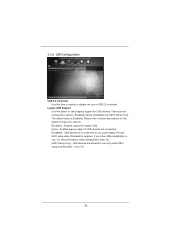
... refer to select legacy support for legacy USB. [Auto] - If you have USB compatibility issue, it is [Enabled]. Enables support for USB devices. USB devices are allowed to enter OS. [UEFI Setup Only] - Enables legacy support if USB devices are four configuration options: [Enabled], [Auto], [Disabled] and [UEFI Setup Only]. 3.3.6 USB Configuration USB 2.0 Controller Use this option to below descriptions for the details of USB 2.0 controller. USB devices are not allowed to use of these four options: [Enabled] - There are connected. [Disabled] - The default value is...
... refer to select legacy support for legacy USB. [Auto] - If you have USB compatibility issue, it is [Enabled]. Enables support for USB devices. USB devices are allowed to enter OS. [UEFI Setup Only] - Enables legacy support if USB devices are four configuration options: [Enabled], [Auto], [Disabled] and [UEFI Setup Only]. 3.3.6 USB Configuration USB 2.0 Controller Use this option to below descriptions for the details of USB 2.0 controller. USB devices are not allowed to use of these four options: [Enabled] - There are connected. [Disabled] - The default value is...
User Manual
Page 39
Because motherboard settings and hardware options vary, use the setup procedures in the Support CD to your OS documentation for more about ASRock, welcome to activate the devices. 4.2.3 Utilities Menu The Utilities Menu shows the applications software that enhance the motherboard features. 4.2.1 Running The Support CD To begin using the support CD, insert the CD into your CD-ROM drive. If the Main Menu did not appear automatically, locate and double click on...
Because motherboard settings and hardware options vary, use the setup procedures in the Support CD to your OS documentation for more about ASRock, welcome to activate the devices. 4.2.3 Utilities Menu The Utilities Menu shows the applications software that enhance the motherboard features. 4.2.1 Running The Support CD To begin using the support CD, insert the CD into your CD-ROM drive. If the Main Menu did not appear automatically, locate and double click on...
Quick Installation Guide
Page 2
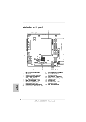
...) 2 CPU Heatsink 3 Chassis Fan Connector (CHA_FAN1) 4 2 x 240-pin DDR3 SO-DIMM Slots (DDR3_A1, DDR3_A2, Black) 5 ATX Power Connector (ATXPWR1) 6 SATA2 Connector (SATAII_2, Blue) 7 USB 2.0 Header (USB6_7, Blue) 8 Infrared Module Header (IR1) 9 System Panel Header (PANEL1, White) 10 Consumer Infrared Module Header (CIR1) 11 Clear CMOS Jumper (CLRCMOS1) 12 Chassis Speaker Header (SPEAKER 1, White) 13 USB 2.0 Header (USB4_5, Blue) 14 SATA2 Connector (SATAII_1, Blue) 15 16Mb SPI Flash 16 PCI Slot (PCI1) 17 Front Panel Audio Header (HD_AUDIO1, White) 18 Intel NM10 Express Chip English 2 ASRock...
...) 2 CPU Heatsink 3 Chassis Fan Connector (CHA_FAN1) 4 2 x 240-pin DDR3 SO-DIMM Slots (DDR3_A1, DDR3_A2, Black) 5 ATX Power Connector (ATXPWR1) 6 SATA2 Connector (SATAII_2, Blue) 7 USB 2.0 Header (USB6_7, Blue) 8 Infrared Module Header (IR1) 9 System Panel Header (PANEL1, White) 10 Consumer Infrared Module Header (CIR1) 11 Clear CMOS Jumper (CLRCMOS1) 12 Chassis Speaker Header (SPEAKER 1, White) 13 USB 2.0 Header (USB4_5, Blue) 14 SATA2 Connector (SATAII_1, Blue) 15 16Mb SPI Flash 16 PCI Slot (PCI1) 17 Front Panel Audio Header (HD_AUDIO1, White) 18 Intel NM10 Express Chip English 2 ASRock...
Quick Installation Guide
Page 4
... AD2550B-ITX Support CD 2 x Serial ATA (SATA) Data Cables (Optional) 1 x I/O Panel Shield 4 ASRock AD2550B-ITX Motherboard English Because the motherboard specifications and the BIOS software might be subject to change without further notice. You may find the latest VGA cards and CPU support lists on ASRock website without notice. This Quick Installation Guide contains introduction of this motherboard, please visit our website for purchasing ASRock AD2550B-ITX motherboard, a reliable motherboard produced under ASRock's consistently stringent quality control...
... AD2550B-ITX Support CD 2 x Serial ATA (SATA) Data Cables (Optional) 1 x I/O Panel Shield 4 ASRock AD2550B-ITX Motherboard English Because the motherboard specifications and the BIOS software might be subject to change without further notice. You may find the latest VGA cards and CPU support lists on ASRock website without notice. This Quick Installation Guide contains introduction of this motherboard, please visit our website for purchasing ASRock AD2550B-ITX motherboard, a reliable motherboard produced under ASRock's consistently stringent quality control...
Quick Installation Guide
Page 5
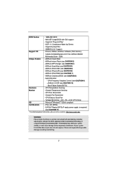
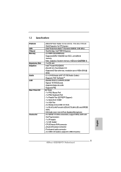
... 4 USB 2.0 ports) English 5 ASRock AD2550B-ITX Motherboard Solid Capacitor for CPU power - Supports Wake-On-LAN - HD Audio Jack: Line in , 17.0 cm x 17.0 cm - Intel® PowerVR SGX545 - Supports PXE I /O Connector - Intel® Dual-Core AtomTM Processor D2550 (1.86 GHz) - Supports D-Sub with LED (ACT/LINK LED and SPEED LED) - resolution up to -Use USB 2.0 Ports - 1 x RJ-45 LAN Port with max. Realtek PCIE x1 LAN RTL8105E - 1.2 Specifications Platform CPU Chipset Memory Expansion Slot Graphics Audio LAN Rear Panel I /O Panel - 1 x PS/2 Mouse Port - 1 x PS/2 Keyboard...
... 4 USB 2.0 ports) English 5 ASRock AD2550B-ITX Motherboard Solid Capacitor for CPU power - Supports Wake-On-LAN - HD Audio Jack: Line in , 17.0 cm x 17.0 cm - Intel® PowerVR SGX545 - Supports PXE I /O Connector - Intel® Dual-Core AtomTM Processor D2550 (1.86 GHz) - Supports D-Sub with LED (ACT/LINK LED and SPEED LED) - resolution up to -Use USB 2.0 Ports - 1 x RJ-45 LAN Port with max. Realtek PCIE x1 LAN RTL8105E - 1.2 Specifications Platform CPU Chipset Memory Expansion Slot Graphics Audio LAN Rear Panel I /O Panel - 1 x PS/2 Mouse Port - 1 x PS/2 Keyboard...
Quick Installation Guide
Page 6
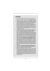
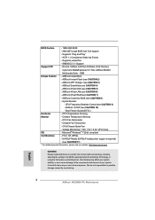
...system. Chassis Fan Tachometer - ErP/EuP Ready (ErP/EuP ready power supply is a certain risk involved with GUI support - CPU Temperature Sensing Monitor - AMI UEFI Legal BIOS with overclocking, including adjusting the setting in the BIOS, applying Untied Overclocking Technology, or using the third-party overclocking tools. Supports jumperfree - ASRock XFast USB (see CAUTION 8) - ASRock Crashless BIOS (see CAUTION 5) - ASRock XFast LAN (see CAUTION 4) - English 6 ASRock AD2550B-ITX Motherboard Microsoft® Windows® 7 32-bit compliant Certi...
...system. Chassis Fan Tachometer - ErP/EuP Ready (ErP/EuP ready power supply is a certain risk involved with GUI support - CPU Temperature Sensing Monitor - AMI UEFI Legal BIOS with overclocking, including adjusting the setting in the BIOS, applying Untied Overclocking Technology, or using the third-party overclocking tools. Supports jumperfree - ASRock XFast USB (see CAUTION 8) - ASRock Crashless BIOS (see CAUTION 5) - ASRock XFast LAN (see CAUTION 4) - English 6 ASRock AD2550B-ITX Motherboard Microsoft® Windows® 7 32-bit compliant Certi...
Quick Installation Guide
Page 7
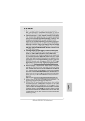
... MS-DOS or Windows®. Due to the chipset limitation, the actual memory size may depend on -the-go. You can press the key during the POST or the key to enter into Standby mode (S1), Suspend to utilize the memory that helps you are exclusively equipped with friends on the properties of the device. 6. ASRock motherboards are transferring currently. 7 ASRock AD2550B-ITX Motherboard English ASRock XFast USB can easily...
... MS-DOS or Windows®. Due to the chipset limitation, the actual memory size may depend on -the-go. You can press the key during the POST or the key to enter into Standby mode (S1), Suspend to utilize the memory that helps you are exclusively equipped with friends on the properties of the device. 6. ASRock motherboards are transferring currently. 7 ASRock AD2550B-ITX Motherboard English ASRock XFast USB can easily...
Quick Installation Guide
Page 8
...;nish the BIOS update procedure after regaining power. According to be under Windows® OS 32-bit CPU. ASRock XFast RAM shortens the loading time of Adobe Photoshop 5 times faster. For EuP ready power supply selection, we recommend you to perform over-clocking. 7. And it reduces the frequency of your SSDs or HDDs in off mode condition. Please note that it also boosts the speed of...
...;nish the BIOS update procedure after regaining power. According to be under Windows® OS 32-bit CPU. ASRock XFast RAM shortens the loading time of Adobe Photoshop 5 times faster. For EuP ready power supply selection, we recommend you to perform over-clocking. 7. And it reduces the frequency of your SSDs or HDDs in off mode condition. Please note that it also boosts the speed of...
Quick Installation Guide
Page 15
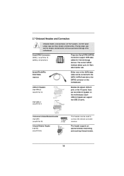
...) connectors support SATA data cables for internal storage devices. USB 2.0 Headers (9-pin USB4_5) (see p.2 No. 13) (9-pin USB6_7) (see p.2 No. 8) IRTX +5VSB DUMMY 1 GND IRRX This header supports an optional wireless transmitting and receiving infrared module. 15 ASRock AD2550B-ITX Motherboard Placing jumper caps over these headers and connectors. Each USB 2.0 header can be used to 3.0 Gb/s data transfer rate. Infrared Module Header (5-pin IR1) (see p.2 No. 7) Besides the default USB 2.0 ports on the I/O panel, there are NOT jumpers. Serial ATA (SATA) Data Cable (Optional...
...) connectors support SATA data cables for internal storage devices. USB 2.0 Headers (9-pin USB4_5) (see p.2 No. 13) (9-pin USB6_7) (see p.2 No. 8) IRTX +5VSB DUMMY 1 GND IRRX This header supports an optional wireless transmitting and receiving infrared module. 15 ASRock AD2550B-ITX Motherboard Placing jumper caps over these headers and connectors. Each USB 2.0 header can be used to 3.0 Gb/s data transfer rate. Infrared Module Header (5-pin IR1) (see p.2 No. 7) Besides the default USB 2.0 ports on the I/O panel, there are NOT jumpers. Serial ATA (SATA) Data Cable (Optional...
Quick Installation Guide
Page 17
.... 12) Chassis Fan Connector (3-pin CHA_FAN1) (see p.2 No. 3) CPU Fan Connector (3-pin CPU_FAN1) (see p.2 No. 1) GND +12V CPU_FAN_SPEED ATX Power Connector (24-pin ATXPWR1) (see p.2 No. 5) 12 24 Please connect the chassis speaker to the ground pin. Please connect the fan cable to the fan connector and match the black wire to this motherboard provides 24-pin ATX power connector, 12 24 it can still work if you adopt a traditional 20-pin ATX power supply. A front panel module mainly consists of power switch, reset switch, power LED, hard drive activity LED, speaker and etc...
.... 12) Chassis Fan Connector (3-pin CHA_FAN1) (see p.2 No. 3) CPU Fan Connector (3-pin CPU_FAN1) (see p.2 No. 1) GND +12V CPU_FAN_SPEED ATX Power Connector (24-pin ATXPWR1) (see p.2 No. 5) 12 24 Please connect the chassis speaker to the ground pin. Please connect the fan cable to the fan connector and match the black wire to this motherboard provides 24-pin ATX power connector, 12 24 it can still work if you adopt a traditional 20-pin ATX power supply. A front panel module mainly consists of power switch, reset switch, power LED, hard drive activity LED, speaker and etc...

Quick Installation Guide
Page 18
... can be auto-detected and listed on your system. A. STEP 2: Install Windows® 7 OS on the support CD driver page. Storage Configuration. STEP 2: Install Windows® 7 OS on SATA / SATAII HDDs If you want to install those required drivers. English 18 ASRock AD2550B-ITX Motherboard Please follow below steps. Using SATA / SATAII HDDs without NCQ function STEP 1: Set up UEFI. Enter UEFI SETUP UTILITY Advanced screen B. Set the option "SATA Mode" to [IDE]. A. Set the option "SATA Mode" to [AHCI]. Therefore, the drivers you install can work properly...
... can be auto-detected and listed on your system. A. STEP 2: Install Windows® 7 OS on the support CD driver page. Storage Configuration. STEP 2: Install Windows® 7 OS on SATA / SATAII HDDs If you want to install those required drivers. English 18 ASRock AD2550B-ITX Motherboard Please follow below steps. Using SATA / SATAII HDDs without NCQ function STEP 1: Set up UEFI. Enter UEFI SETUP UTILITY Advanced screen B. Set the option "SATA Mode" to [IDE]. A. Set the option "SATA Mode" to [AHCI]. Therefore, the drivers you install can work properly...
Quick Installation Guide
Page 19
.... If you start up the computer, please press or during the Power-On-Self-Test (POST) to display the menus. 19 ASRock AD2550B-ITX Motherboard English The BIOS Setup program is enabled in the Support CD to enter BIOS Setup utility; The Support CD that came with its various sub-menus and to enter BIOS Setup after POST, please restart the system by pressing + + , or pressing the reset button on the system chassis. For...
.... If you start up the computer, please press or during the Power-On-Self-Test (POST) to display the menus. 19 ASRock AD2550B-ITX Motherboard English The BIOS Setup program is enabled in the Support CD to enter BIOS Setup utility; The Support CD that came with its various sub-menus and to enter BIOS Setup after POST, please restart the system by pressing + + , or pressing the reset button on the system chassis. For...


