User Manual
Page 5
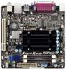
... In case any modifications of the Support CD. ASRock website http://www.asrock.com If you are using. www.asrock.com/support/index.asp 1.1 Package Contents ASRock AD2550B-ITX Motherboard (Mini-ITX Form Factor: 6.7-in x 6.7-in, 17.0 cm x 17.0 cm) ASRock AD2550B-ITX Quick Installation Guide ASRock AD2550B-ITX Support CD 2 x Serial ATA (SATA) Data Cables (...In this manual, chapter 1 and 2 contain introduction of this motherboard, please visit our website for purchasing ASRock AD2550B-ITX motherboard, a reliable motherboard produced under ASRock's consistently stringent quality control.
... In case any modifications of the Support CD. ASRock website http://www.asrock.com If you are using. www.asrock.com/support/index.asp 1.1 Package Contents ASRock AD2550B-ITX Motherboard (Mini-ITX Form Factor: 6.7-in x 6.7-in, 17.0 cm x 17.0 cm) ASRock AD2550B-ITX Quick Installation Guide ASRock AD2550B-ITX Support CD 2 x Serial ATA (SATA) Data Cables (...In this manual, chapter 1 and 2 contain introduction of this motherboard, please visit our website for purchasing ASRock AD2550B-ITX motherboard, a reliable motherboard produced under ASRock's consistently stringent quality control.
Quick Installation Guide
Page 1
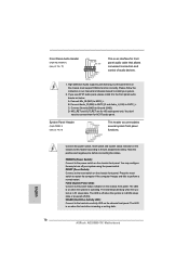
... or conditions of merchantability or fitness for backup purpose, without intent to change without notice, and should not be constructed as a commitment by ASRock. All rights reserved. 1 ASRock AD2550B-ITX Motherboard English Copyright Notice: No part of this installation guide may be reproduced, transcribed, transmitted, or translated in any language, in any form...
... or conditions of merchantability or fitness for backup purpose, without intent to change without notice, and should not be constructed as a commitment by ASRock. All rights reserved. 1 ASRock AD2550B-ITX Motherboard English Copyright Notice: No part of this installation guide may be reproduced, transcribed, transmitted, or translated in any language, in any form...
Quick Installation Guide
Page 2
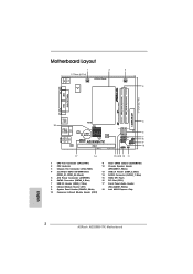
... Center: Line Out Bottom: Mic In USB 2.0 T: USB2 B: USB3 RoHS USB 2.0 T: USB0 B: USB1 Top: RJ-45 AUDIO CODEC LAN PHY CMOS Battery 16Mb BIOS 1 HD_AUDIO1 AD2550B-ITX PCI1 DX10.1 Design in Taipei SATAII_1 SATAII_2 1 1 1 CIR1 SPEAKER1 1 USB6_7 IR1 1 USB4_5 PLED PWRBTN 1 HDLED RESET PANEL 1 CLRCMOS1 1 5 6 7 8 9 10 17 16 151413 12 11 1 CPU... SATA2 Connector (SATAII_1, Blue) 15 16Mb SPI Flash 16 PCI Slot (PCI1) 17 Front Panel Audio Header (HD_AUDIO1, White) 18 Intel NM10 Express Chip English 2 ASRock AD2550B-ITX Motherboard
... Center: Line Out Bottom: Mic In USB 2.0 T: USB2 B: USB3 RoHS USB 2.0 T: USB0 B: USB1 Top: RJ-45 AUDIO CODEC LAN PHY CMOS Battery 16Mb BIOS 1 HD_AUDIO1 AD2550B-ITX PCI1 DX10.1 Design in Taipei SATAII_1 SATAII_2 1 1 1 CIR1 SPEAKER1 1 USB6_7 IR1 1 USB4_5 PLED PWRBTN 1 HDLED RESET PANEL 1 CLRCMOS1 1 5 6 7 8 9 10 17 16 151413 12 11 1 CPU... SATA2 Connector (SATAII_1, Blue) 15 16Mb SPI Flash 16 PCI Slot (PCI1) 17 Front Panel Audio Header (HD_AUDIO1, White) 18 Intel NM10 Express Chip English 2 ASRock AD2550B-ITX Motherboard
Quick Installation Guide
Page 3
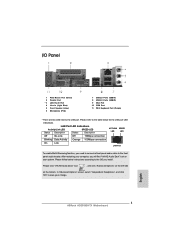
... HD Audio Deck" tool on the bottom. Please click "VIA HD Audio Deck" icon , and click "Advanced Options" on the left side on your change. 3 ASRock AD2550B-ITX Motherboard English Please follow below for the LAN port LED indications. I/O Panel 1 PS/2 Mouse Port (Green) 2 Parallel Port * 3 LAN RJ-45 Port 4 Line In (Light...
... HD Audio Deck" tool on the bottom. Please click "VIA HD Audio Deck" icon , and click "Advanced Options" on the left side on your change. 3 ASRock AD2550B-ITX Motherboard English Please follow below for the LAN port LED indications. I/O Panel 1 PS/2 Mouse Port (Green) 2 Parallel Port * 3 LAN RJ-45 Port 4 Line In (Light...
Quick Installation Guide
Page 4
... will be found in the user manual presented in , 17.0 cm x 17.0 cm) ASRock AD2550B-ITX Quick Installation Guide ASRock AD2550B-ITX Support CD 2 x Serial ATA (SATA) Data Cables (Optional) 1 x I/O Panel Shield 4 ASRock AD2550B-ITX Motherboard English www.asrock.com/support/index.asp 1.1 Package Contents ASRock AD2550B-ITX Motherboard (Mini-ITX Form Factor: 6.7-in x 6.7-in the Support CD. More detailed information of the motherboard...
... will be found in the user manual presented in , 17.0 cm x 17.0 cm) ASRock AD2550B-ITX Quick Installation Guide ASRock AD2550B-ITX Support CD 2 x Serial ATA (SATA) Data Cables (Optional) 1 x I/O Panel Shield 4 ASRock AD2550B-ITX Motherboard English www.asrock.com/support/index.asp 1.1 Package Contents ASRock AD2550B-ITX Motherboard (Mini-ITX Form Factor: 6.7-in x 6.7-in the Support CD. More detailed information of the motherboard...
Quick Installation Guide
Page 5
... to -Use USB 2.0 Ports - 1 x RJ-45 LAN Port with max. Realtek PCIE x1 LAN RTL8105E - Supports Wake-On-LAN - Mini-ITX Form Factor: 6.7-in x 6.7-in /Front Speaker/Microphone - 2 x SATA2 3.0 Gb/s connectors, support NCQ, AHCI and Hot Plug functions - 1...- Intel® PowerVR SGX545 - Supports THX TruStudioTM - Front panel audio connector - 2 x USB 2.0 headers (support 4 USB 2.0 ports) English 5 ASRock AD2550B-ITX Motherboard Solid Capacitor for CPU power - DirectX 9.0, Pixel Shader 3.0 - 1.2 Specifications Platform CPU Chipset Memory Expansion Slot Graphics Audio LAN Rear Panel I /O...
... to -Use USB 2.0 Ports - 1 x RJ-45 LAN Port with max. Realtek PCIE x1 LAN RTL8105E - Supports Wake-On-LAN - Mini-ITX Form Factor: 6.7-in x 6.7-in /Front Speaker/Microphone - 2 x SATA2 3.0 Gb/s connectors, support NCQ, AHCI and Hot Plug functions - 1...- Intel® PowerVR SGX545 - Supports THX TruStudioTM - Front panel audio connector - 2 x USB 2.0 headers (support 4 USB 2.0 ports) English 5 ASRock AD2550B-ITX Motherboard Solid Capacitor for CPU power - DirectX 9.0, Pixel Shader 3.0 - 1.2 Specifications Platform CPU Chipset Memory Expansion Slot Graphics Audio LAN Rear Panel I /O...
Quick Installation Guide
Page 6
... Monitoring: +12V, +5V, +3.3V, CPU Vcore OS - It should be done at your system. English 6 ASRock AD2550B-ITX Motherboard AMI UEFI Legal BIOS with overclocking, including adjusting the setting in the BIOS, applying Untied Overclocking Technology, or using...third-party overclocking tools. Supports "Plug and Play" - Hybrid Booster: - Microsoft® Windows® 7 32-bit compliant Certifications - ASRock Crashless BIOS (see CAUTION 4) - Boot Failure Guard (B.F.G.) Hardware - BIOS Feature - 16Mb AMI BIOS - CPU Fan Tachometer - Overclocking may affect ...
... Monitoring: +12V, +5V, +3.3V, CPU Vcore OS - It should be done at your system. English 6 ASRock AD2550B-ITX Motherboard AMI UEFI Legal BIOS with overclocking, including adjusting the setting in the BIOS, applying Untied Overclocking Technology, or using...third-party overclocking tools. Supports "Plug and Play" - Hybrid Booster: - Microsoft® Windows® 7 32-bit compliant Certifications - ASRock Crashless BIOS (see CAUTION 4) - Boot Failure Guard (B.F.G.) Hardware - BIOS Feature - 16Mb AMI BIOS - CPU Fan Tachometer - Overclocking may affect ...
Quick Installation Guide
Page 7
...function for internet browsers, is a BIOS flash utility embedded in games. ASRock motherboards are transferring currently. 7 ASRock AD2550B-ITX Motherboard English ASRock website: http://www.asrock.com/Feature/SmartView/index.asp 5. ASRock APP Charger. ASRock XFast LAN provides a faster internet access, which data streams you to RAM (...diskette or other complicated flash utility. This convenient BIOS update tool allows you are exclusively equipped with the ASRock SmartView utility that the USB flash drive or hard drive must use FAT32/16/12 file system....
...function for internet browsers, is a BIOS flash utility embedded in games. ASRock motherboards are transferring currently. 7 ASRock AD2550B-ITX Motherboard English ASRock website: http://www.asrock.com/Feature/SmartView/index.asp 5. ASRock APP Charger. ASRock XFast LAN provides a faster internet access, which data streams you to RAM (...diskette or other complicated flash utility. This convenient BIOS update tool allows you are exclusively equipped with the ASRock SmartView utility that the USB flash drive or hard drive must use FAT32/16/12 file system....
Quick Installation Guide
Page 8
... automatically finish the BIOS update procedure after regaining power. According to check with the power supply manufacturer for more details. 8 ASRock AD2550B-ITX Motherboard English EuP stands for the completed system. ASRock Crashless BIOS allows users to extend their BIOS without fear of 5v, and the standby power efficiency should be...
... automatically finish the BIOS update procedure after regaining power. According to check with the power supply manufacturer for more details. 8 ASRock AD2550B-ITX Motherboard English EuP stands for the completed system. ASRock Crashless BIOS allows users to extend their BIOS without fear of 5v, and the standby power efficiency should be...
Quick Installation Guide
Page 9
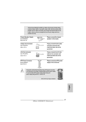
... cause severe damage to the chassis. Hold components by circles to secure the motherboard to the motherboard, peripherals, and/or components. 9 ASRock AD2550B-ITX Motherboard English Whenever you install motherboard components or change any component, place it . To avoid damaging the motherboard components due to use .... Failure to unplug the power cord before touching any component, ensure that the power is switched off or the power cord is a Mini-ITX form factor (6.7" x 6.7", 17.0 x 17.0 cm) motherboard. Do not over-tighten the screws! Make sure to do so may damage...
... cause severe damage to the chassis. Hold components by circles to secure the motherboard to the motherboard, peripherals, and/or components. 9 ASRock AD2550B-ITX Motherboard English Whenever you install motherboard components or change any component, place it . To avoid damaging the motherboard components due to use .... Failure to unplug the power cord before touching any component, ensure that the power is switched off or the power cord is a Mini-ITX form factor (6.7" x 6.7", 17.0 x 17.0 cm) motherboard. Do not over-tighten the screws! Make sure to do so may damage...
Quick Installation Guide
Page 10
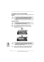
...DIMM is not allowed to disconnect power supply before adding or removing SO-DIMMs or the system components. 2.3 Installation of Memory Modules (SO-DIMM) AD2550B-ITX motherboard provides two 240-pin DDR3 (Double Data Rate 3) SODIMM slots. 1. otherwise, this motherboard and SO-DIMM may be damaged. 2. Step ...SO-DIMM if you force the SODIMM into the slot until the retaining clips at incorrect orientation. Step 1. It is properly seated. 10 ASRock AD2550B-ITX Motherboard Installing a SO-DIMM Please make sure to install a DDR or DDR2 memory module into DDR3 slot; Align a SO-DIMM on the...
...DIMM is not allowed to disconnect power supply before adding or removing SO-DIMMs or the system components. 2.3 Installation of Memory Modules (SO-DIMM) AD2550B-ITX motherboard provides two 240-pin DDR3 (Double Data Rate 3) SODIMM slots. 1. otherwise, this motherboard and SO-DIMM may be damaged. 2. Step ...SO-DIMM if you force the SODIMM into the slot until the retaining clips at incorrect orientation. Step 1. It is properly seated. 10 ASRock AD2550B-ITX Motherboard Installing a SO-DIMM Please make sure to install a DDR or DDR2 memory module into DDR3 slot; Align a SO-DIMM on the...
Quick Installation Guide
Page 11
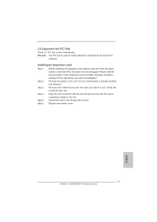
Installing an expansion card Step 1. Keep the screws for the card before you intend to use . Replace the system cover. 11 ASRock AD2550B-ITX Motherboard English Please read the documentation of the expansion card and make sure that you start the installation. Step 2. Align the card connector with screws. ...
Installing an expansion card Step 1. Keep the screws for the card before you intend to use . Replace the system cover. 11 ASRock AD2550B-ITX Motherboard English Please read the documentation of the expansion card and make sure that you start the installation. Step 2. Align the card connector with screws. ...
Quick Installation Guide
Page 12
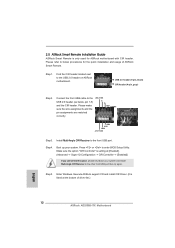
... used for the quick installation and usage of driver list.) English 12 ASRock AD2550B-ITX Motherboard Step1. Press or to the front USB port. Enter Windows. Please refer to the USB 2.0 header (as below procedures for ASRock motherboard with CIR header. Connect the front USB cable to below ,...Angle CIR Receiver to the USB 2.0 header on ASRock motherboard. USB_PWR PP+ GND DUMMY 1 23 45 GND IRTX IRRX ATX+5VSB Step3. Execute ASRock support CD and install CIR Driver. (It is setting at the bottom of ASRock Smart Remote. Please make sure the wire assignments ...
... used for the quick installation and usage of driver list.) English 12 ASRock AD2550B-ITX Motherboard Step1. Press or to the front USB port. Enter Windows. Please refer to the USB 2.0 header (as below procedures for ASRock motherboard with CIR header. Connect the front USB cable to below ,...Angle CIR Receiver to the USB 2.0 header on ASRock motherboard. USB_PWR PP+ GND DUMMY 1 23 45 GND IRTX IRRX ATX+5VSB Step3. Execute ASRock support CD and install CIR Driver. (It is setting at the bottom of ASRock Smart Remote. Please make sure the wire assignments ...

Quick Installation Guide
Page 13
... different angles 1. Only one of the chassis on the rear panel. When the CIR function is used for the motherboard support list: http://www.asrock.com 13 ASRock AD2550B-ITX Motherboard English Multi-Angle CIR Receiver can support CIR function. Please install it on the market. 3. Please do not use the rear USB bracket...
... different angles 1. Only one of the chassis on the rear panel. When the CIR function is used for the motherboard support list: http://www.asrock.com 13 ASRock AD2550B-ITX Motherboard English Multi-Angle CIR Receiver can support CIR function. Please install it on the market. 3. Please do not use the rear USB bracket...
Quick Installation Guide
Page 14
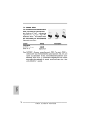
English 14 ASRock AD2550B-ITX Motherboard Jumper Clear CMOS (CLRCMOS1, 2-pin jumper) (see p.2 No. 11) Setting 2-pin jumper Description Note: CLRCMOS1 allows you to clear the data in CMOS includes ...
English 14 ASRock AD2550B-ITX Motherboard Jumper Clear CMOS (CLRCMOS1, 2-pin jumper) (see p.2 No. 11) Setting 2-pin jumper Description Note: CLRCMOS1 allows you to clear the data in CMOS includes ...
Quick Installation Guide
Page 15
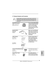
... USB4_5) (see p.2 No. 13) (9-pin USB6_7) (see p.2 No. 8) IRTX +5VSB DUMMY 1 GND IRRX This header supports an optional wireless transmitting and receiving infrared module. 15 ASRock AD2550B-ITX Motherboard Placing jumper caps over these headers and connectors. Serial ATA2 Connectors (SATAII_1: see p.2, No. 14) (SATAII_2: see p.2 No. 10) 1 GND IRTX IRRX ATX+5VSB...
... USB4_5) (see p.2 No. 13) (9-pin USB6_7) (see p.2 No. 8) IRTX +5VSB DUMMY 1 GND IRRX This header supports an optional wireless transmitting and receiving infrared module. 15 ASRock AD2550B-ITX Motherboard Placing jumper caps over these headers and connectors. Serial ATA2 Connectors (SATAII_1: see p.2, No. 14) (SATAII_2: see p.2 No. 10) 1 GND IRTX IRRX ATX+5VSB...
Quick Installation Guide
Page 16
... off when the system is in our manual and chassis manual to the reset switch on when the system is reading or writing data. 16 ASRock AD2550B-ITX Motherboard English C. You may configure the way to Ground (GND). Press the reset switch to restart the computer if the computer freezes and...
... off when the system is in our manual and chassis manual to the reset switch on when the system is reading or writing data. 16 ASRock AD2550B-ITX Motherboard English C. You may configure the way to Ground (GND). Press the reset switch to restart the computer if the computer freezes and...
Quick Installation Guide
Page 17
... 20-pin ATX power supply. When connecting your power supply along with Pin 1 and Pin 13. 20-Pin ATX Power Supply Installation 1 13 English 17 ASRock AD2550B-ITX Motherboard A front panel module mainly consists of power switch, reset switch, power LED, hard drive activity LED, speaker and etc. The front panel design may...
... 20-pin ATX power supply. When connecting your power supply along with Pin 1 and Pin 13. 20-Pin ATX Power Supply Installation 1 13 English 17 ASRock AD2550B-ITX Motherboard A front panel module mainly consists of power switch, reset switch, power LED, hard drive activity LED, speaker and etc. The front panel design may...

Quick Installation Guide
Page 18
... your system. Enter UEFI SETUP UTILITY Advanced screen B. STEP 2: Install Windows® 7 OS on the support CD driver page. Storage Configuration. English 18 ASRock AD2550B-ITX Motherboard Using SATA / SATAII HDDs with NCQ function STEP 1: Set up UEFI. Storage Configuration. Please follow below steps. Set the option "SATA Mode...
... your system. Enter UEFI SETUP UTILITY Advanced screen B. STEP 2: Install Windows® 7 OS on the support CD driver page. Storage Configuration. English 18 ASRock AD2550B-ITX Motherboard Using SATA / SATAII HDDs with NCQ function STEP 1: Set up UEFI. Storage Configuration. Please follow below steps. Set the option "SATA Mode...
Quick Installation Guide
Page 19
.... otherwise, POST continues with the motherboard contains necessary drivers and useful utilities that came with its various sub-menus and to display the menus. 19 ASRock AD2550B-ITX Motherboard English If you start up the computer, please press or during the Power-On-Self-Test (POST) to scroll through its test routines. To...
.... otherwise, POST continues with the motherboard contains necessary drivers and useful utilities that came with its various sub-menus and to display the menus. 19 ASRock AD2550B-ITX Motherboard English If you start up the computer, please press or during the Power-On-Self-Test (POST) to scroll through its test routines. To...


