
User Manual
Page 2
... In no responsibility for identification or explanation and to infringe. CALIFORNIA, USA ONLY The Lithium battery adopted on this motherboard contains Perchlorate, a toxic substance controlled in Perchlorate Best Management Practices (BMP) regulations passed by the purchaser for a particular purpose.... With respect to the contents of this manual, ASRock does not provide warranty of any kind, either expressed or implied, including but not limited to the implied warranties or conditions of...
... In no responsibility for identification or explanation and to infringe. CALIFORNIA, USA ONLY The Lithium battery adopted on this motherboard contains Perchlorate, a toxic substance controlled in Perchlorate Best Management Practices (BMP) regulations passed by the purchaser for a particular purpose.... With respect to the contents of this manual, ASRock does not provide warranty of any kind, either expressed or implied, including but not limited to the implied warranties or conditions of...

User Manual
Page 3
Contents 1 Introduction 5 1.1 Package Contents 5 1.2 Specifications 6 1.3 Motherboard Layout 10 1.4 I/O Panel 11 2 Installation 12 2.1 Screw Holes 12 2.2 Pre-installation Precautions 12 2.3 Installation of Memory Modules (SO-DIMM 13 2.4 Expansion Slot (PCI Slot 14 2.5 ASRock Smart Remote Installation Guide 15 2.6 Jumpers Setup 17 2.7 Onboard Headers and Connectors 18 2.8 Serial ATA (SATA) / Serial ATA2 (SATA2...
Contents 1 Introduction 5 1.1 Package Contents 5 1.2 Specifications 6 1.3 Motherboard Layout 10 1.4 I/O Panel 11 2 Installation 12 2.1 Screw Holes 12 2.2 Pre-installation Precautions 12 2.3 Installation of Memory Modules (SO-DIMM 13 2.4 Expansion Slot (PCI Slot 14 2.5 ASRock Smart Remote Installation Guide 15 2.6 Jumpers Setup 17 2.7 Onboard Headers and Connectors 18 2.8 Serial ATA (SATA) / Serial ATA2 (SATA2...
User Manual
Page 5
... be updated, the content of this manual, chapter 1 and 2 contain introduction of the Support CD. www.asrock.com/support/index.asp 1.1 Package Contents ASRock AD2550B-ITX Motherboard (Mini-ITX Form Factor: 6.7-in x 6.7-in, 17.0 cm x 17.0 cm) ASRock AD2550B-ITX Quick Installation Guide ASRock AD2550B-ITX Support CD 2 x Serial ATA (SATA) Data Cables (Optional) 1 x I/O Panel Shield 5 Chapter 3 and 4 contain the confi...
... be updated, the content of this manual, chapter 1 and 2 contain introduction of the Support CD. www.asrock.com/support/index.asp 1.1 Package Contents ASRock AD2550B-ITX Motherboard (Mini-ITX Form Factor: 6.7-in x 6.7-in, 17.0 cm x 17.0 cm) ASRock AD2550B-ITX Quick Installation Guide ASRock AD2550B-ITX Support CD 2 x Serial ATA (SATA) Data Cables (Optional) 1 x I/O Panel Shield 5 Chapter 3 and 4 contain the confi...
User Manual
Page 8
...faster, less restricted way of the device. 6. ASRock website: http://www.asrock.com/Feature/SmartView/index.asp 5. You can lower the latency in a few clicks without entering operating systems first like MS-DOS or Windows®. ASRock motherboards are transferring currently. 8 Due to your browser ...version is IE8. ASRock Instant Flash is the smart start page for you can press the key during the POST or...
...faster, less restricted way of the device. 6. ASRock website: http://www.asrock.com/Feature/SmartView/index.asp 5. You can lower the latency in a few clicks without entering operating systems first like MS-DOS or Windows®. ASRock motherboards are transferring currently. 8 Due to your browser ...version is IE8. ASRock Instant Flash is the smart start page for you can press the key during the POST or...
User Manual
Page 9
...European Union to Intel's suggestion, the EuP ready power supply must meet EuP standards, an EuP ready motherboard and an EuP ready power supply are required. Only USB2.0 ports support this motherboard offers stepless control, it reduces the frequency of accessing your SSDs or HDDs in the root directory of... Before you resume the system, please check if the CPU fan on the motherboard functions properly and unplug the power cord, then plug it also boosts the speed of your USB disk. And it back again. ASRock Crashless BIOS allows users to extend their BIOS without fear of 5v, and ...
...European Union to Intel's suggestion, the EuP ready power supply must meet EuP standards, an EuP ready motherboard and an EuP ready power supply are required. Only USB2.0 ports support this motherboard offers stepless control, it reduces the frequency of accessing your SSDs or HDDs in the root directory of... Before you resume the system, please check if the CPU fan on the motherboard functions properly and unplug the power cord, then plug it also boosts the speed of your USB disk. And it back again. ASRock Crashless BIOS allows users to extend their BIOS without fear of 5v, and ...
User Manual
Page 10
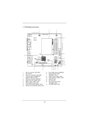
1.3 Motherboard Layout PS2 Mouse PS2 Keyboard 1 2 3 17.0cm (6.7 in) CPU_FAN1 ErP/EuP Ready CHA_FAN1 4 Super IO 17.0cm (6.7 in) DDR3_A2 (64 bit, 204-FpiSnBm8o0d0ule) DDR3_A1 (64 ... Center: Line Out Bottom: Mic In USB 2.0 T: USB2 B: USB3 RoHS USB 2.0 T: USB0 B: USB1 Top: RJ-45 AUDIO CODEC LAN PHY CMOS Battery 16Mb BIOS 1 HD_AUDIO1 AD2550B-ITX PCI1 DX10.1 Design in Taipei SATAII_1 SATAII_2 1 1 1 CIR1 SPEAKER1 1 USB6_7 IR1 1 USB4_5 PLED PWRBTN 1 HDLED RESET PANEL 1 CLRCMOS1 1 5 6 7 8 9 10 17 16 151413 12 11 1 CPU...
1.3 Motherboard Layout PS2 Mouse PS2 Keyboard 1 2 3 17.0cm (6.7 in) CPU_FAN1 ErP/EuP Ready CHA_FAN1 4 Super IO 17.0cm (6.7 in) DDR3_A2 (64 bit, 204-FpiSnBm8o0d0ule) DDR3_A1 (64 ... Center: Line Out Bottom: Mic In USB 2.0 T: USB2 B: USB3 RoHS USB 2.0 T: USB0 B: USB1 Top: RJ-45 AUDIO CODEC LAN PHY CMOS Battery 16Mb BIOS 1 HD_AUDIO1 AD2550B-ITX PCI1 DX10.1 Design in Taipei SATAII_1 SATAII_2 1 1 1 CIR1 SPEAKER1 1 USB6_7 IR1 1 USB4_5 PLED PWRBTN 1 HDLED RESET PANEL 1 CLRCMOS1 1 5 6 7 8 9 10 17 16 151413 12 11 1 CPU...
User Manual
Page 12
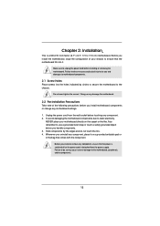
...note of your chassis to static electricity, NEVER place your motherboard directly on a grounded antistatic pad or in the bag that the power is switched off or the power cord is a Mini-ITX form factor (6.7" x 6.7", 17.0 x 17.0 cm) motherboard. Unplug the power cord from the power supply. Hold... components by circles to secure the motherboard to do not touch the ICs. 4. Failure to the chassis. Chapter 2: ...
...note of your chassis to static electricity, NEVER place your motherboard directly on a grounded antistatic pad or in the bag that the power is switched off or the power cord is a Mini-ITX form factor (6.7" x 6.7", 17.0 x 17.0 cm) motherboard. Unplug the power cord from the power supply. Hold... components by circles to secure the motherboard to do not touch the ICs. 4. Failure to the chassis. Chapter 2: ...
User Manual
Page 13
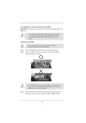
It is properly seated. 13 Installing a SO-DIMM Please make sure to the motherboard and the SO-DIMM if you force the SODIMM into the slot until the retaining clips at incorrect orientation. Step 2. notch break notch break The ... SO-DIMMs or the system components. Please install the memory module from DDR3_A2 slot for the first priority. 2.3 Installation of Memory Modules (SO-DIMM) AD2550B-ITX motherboard provides two 240-pin DDR3 (Double Data Rate 3) SODIMM slots. 1. Firmly insert the SO-DIMM into the slot at both ends fully snap back in...
It is properly seated. 13 Installing a SO-DIMM Please make sure to the motherboard and the SO-DIMM if you force the SODIMM into the slot until the retaining clips at incorrect orientation. Step 2. notch break notch break The ... SO-DIMMs or the system components. Please install the memory module from DDR3_A2 slot for the first priority. 2.3 Installation of Memory Modules (SO-DIMM) AD2550B-ITX motherboard provides two 240-pin DDR3 (Double Data Rate 3) SODIMM slots. 1. Firmly insert the SO-DIMM into the slot at both ends fully snap back in...
User Manual
Page 14
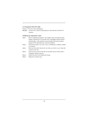
... unplugged. Step 2. Step 4. Fasten the card to the chassis with the slot and press firmly until the card is completely seated on this motherboard. Step 6. Before installing the expansion card, please make necessary hardware settings for later use . Keep the screws for the card before you intend to install ...
... unplugged. Step 2. Step 4. Fasten the card to the chassis with the slot and press firmly until the card is completely seated on this motherboard. Step 6. Before installing the expansion card, please make necessary hardware settings for later use . Keep the screws for the card before you intend to install ...
User Manual
Page 15
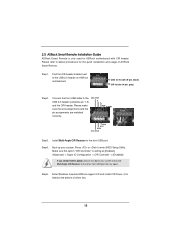
... IRRX ATX+5VSB Step3. 2.5 ASRock Smart Remote Installation Guide ASRock Smart Remote is setting at the bottom of ASRock Smart Remote. Step1. Step4. Boot up your system and install Multi-Angle CIR Receiver to the USB 2.0 header (as below procedures for ASRock motherboard with CIR header. Step5. Connect... the front USB cable to the other front USB port then try again. Please refer to the USB 2.0 header on ASRock motherboard. Press or to the front USB port. Find the...
... IRRX ATX+5VSB Step3. 2.5 ASRock Smart Remote Installation Guide ASRock Smart Remote is setting at the bottom of ASRock Smart Remote. Step1. Step4. Boot up your system and install Multi-Angle CIR Receiver to the USB 2.0 header (as below procedures for ASRock motherboard with CIR header. Step5. Connect... the front USB cable to the other front USB port then try again. Please refer to the USB 2.0 header on ASRock motherboard. Press or to the front USB port. Find the...

User Manual
Page 16
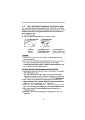
... install it on the market. 3. Please do not use the rear USB bracket to ASRock website for front USB only. Please refer to connect it before you boot the system. * ASRock Smart Remote is compatible with most of ASRock motherboards. Only one of the front USB port can receive the multi-direction infrared signals... is only supported by some of the chassis on the rear panel. 3 CIR sensors in different angles 1. When the CIR function is used for the motherboard support list: http://www.asrock.com 16 The Multi-Angle CIR Receiver does not support Hot-Plug function.
... install it on the market. 3. Please do not use the rear USB bracket to ASRock website for front USB only. Please refer to connect it before you boot the system. * ASRock Smart Remote is compatible with most of ASRock motherboards. Only one of the front USB port can receive the multi-direction infrared signals... is only supported by some of the chassis on the rear panel. 3 CIR sensors in different angles 1. When the CIR function is used for the motherboard support list: http://www.asrock.com 16 The Multi-Angle CIR Receiver does not support Hot-Plug function.
User Manual
Page 18
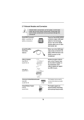
... ATA2 (SATA2) connectors support SATA data cables for internal storage devices. 2.7 Onboard Headers and Connectors Onboard headers and connectors are two USB 2.0 headers on this motherboard. Serial ATA2 Connectors (SATAII_1: see p.10, No. 14) (SATAII_2: see p.10 No. 8) IRTX +5VSB DUMMY 1 GND IRRX This header supports an... 1 GND IRTX IRRX ATX+5VSB This header can be connected to the SATA / SATA2 hard disk or the SATA2 connector on this motherboard. Each USB 2.0 header can be used to 3.0 Gb/s data transfer rate. Serial ATA (SATA) Data Cable (Optional) Either end of the...
... ATA2 (SATA2) connectors support SATA data cables for internal storage devices. 2.7 Onboard Headers and Connectors Onboard headers and connectors are two USB 2.0 headers on this motherboard. Serial ATA2 Connectors (SATAII_1: see p.10, No. 14) (SATAII_2: see p.10 No. 8) IRTX +5VSB DUMMY 1 GND IRRX This header supports an... 1 GND IRTX IRRX ATX+5VSB This header can be connected to the SATA / SATA2 hard disk or the SATA2 connector on this motherboard. Each USB 2.0 header can be used to 3.0 Gb/s data transfer rate. Serial ATA (SATA) Data Cable (Optional) Either end of the...
User Manual
Page 20
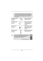
... CPU_FAN1) (see p.10 No. 1) GND +12V CPU_FAN_SPEED ATX Power Connector (24-pin ATXPWR1) (see p.10 No. 5) 12 24 Please connect the chassis speaker to this motherboard provides 24-pin ATX power connector, 12 24 it can still work if you adopt a traditional 20-pin ATX power supply. To use the 20...
... CPU_FAN1) (see p.10 No. 1) GND +12V CPU_FAN_SPEED ATX Power Connector (24-pin ATXPWR1) (see p.10 No. 5) 12 24 Please connect the chassis speaker to this motherboard provides 24-pin ATX power connector, 12 24 it can still work if you adopt a traditional 20-pin ATX power supply. To use the 20...
User Manual
Page 21
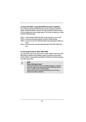
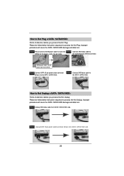
...perform Hot Plug if the OS has been installed into the drive bays of your chassis. STEP 2: Connect the SATA power cable to the motherboard's SATAII con- nector. Intel® NM10 Express chipset provides hardware support for Advanced Host controller Interface (AHCI), a new programming interface for ... other end of the SATA data cable to the SATA / SATAII hard disk. 2.9 Hot Plug Function for SATA / SATAII HDDs This motherboard supports Hot Plug function for SATA host controllers developed thru a joint industry effort. 2.8 Serial ATA (SATA) / Serial ATAII (SATAII) Hard Disks Installation ...
...perform Hot Plug if the OS has been installed into the drive bays of your chassis. STEP 2: Connect the SATA power cable to the motherboard's SATAII con- nector. Intel® NM10 Express chipset provides hardware support for Advanced Host controller Interface (AHCI), a new programming interface for ... other end of the SATA data cable to the SATA / SATAII hard disk. 2.9 Hot Plug Function for SATA / SATAII HDDs This motherboard supports Hot Plug function for SATA host controllers developed thru a joint industry effort. 2.8 Serial ATA (SATA) / Serial ATAII (SATAII) Hard Disks Installation ...
User Manual
Page 22
... connector interfaces, the IDE 1x4-pin conventional power connector interface is available on our website: www.asrock.com 2. Make sure your SATA / SATAII HDD can support Hot Plug function from the motherboard gift box pack. SATA data cable (Red) B. SATA power cable SATA 7-pin connector The ...Hot Plug operation. 3. Points of attention, before you process the SATA / SATAII HDD Hot Plug, please check below operation guide of our motherboard is installed into system properly. SATA power cable with SATA 15-pin power connector interface A. 2.10 SATA / SATAII HDD Hot Plug Feature ...
... connector interfaces, the IDE 1x4-pin conventional power connector interface is available on our website: www.asrock.com 2. Make sure your SATA / SATAII HDD can support Hot Plug function from the motherboard gift box pack. SATA data cable (Red) B. SATA power cable SATA 7-pin connector The ...Hot Plug operation. 3. Points of attention, before you process the SATA / SATAII HDD Hot Plug, please check below operation guide of our motherboard is installed into system properly. SATA power cable with SATA 15-pin power connector interface A. 2.10 SATA / SATAII HDD Hot Plug Feature ...
User Manual
Page 23
the motherboard's SATAII connector. SATA power cable 1x4-pin power connector (White) Step 3 Connect SATA 15-pin power cable connector (Black) end to the power supply 1x4-...
the motherboard's SATAII connector. SATA power cable 1x4-pin power connector (White) Step 3 Connect SATA 15-pin power cable connector (Black) end to the power supply 1x4-...

User Manual
Page 25
..., the following UEFI setup screens and descriptions are for reference purpose only, and they may run the UEFI SETUP UTILITY when you see on the motherboard stores the UEFI SETUP UTILITY. You may not exactly match what you start up the security features Exit To exit the current screen or the...
..., the following UEFI setup screens and descriptions are for reference purpose only, and they may run the UEFI SETUP UTILITY when you see on the motherboard stores the UEFI SETUP UTILITY. You may not exactly match what you start up the security features Exit To exit the current screen or the...

User Manual
Page 29
...]. Front Panel Select [Auto] or [Disabled] for the onboard HD Audio feature. If [Power Off] is [Auto]. 29 Restore on . Good Night LED Enable this motherboard to enable or disable ACPI HPET Table. Please set the power state after an unexpected AC/power loss. The default value is selected, the AC...
...]. Front Panel Select [Auto] or [Disabled] for the onboard HD Audio feature. If [Power Off] is [Auto]. 29 Restore on . Good Night LED Enable this motherboard to enable or disable ACPI HPET Table. Please set the power state after an unexpected AC/power loss. The default value is selected, the AC...
User Manual
Page 35
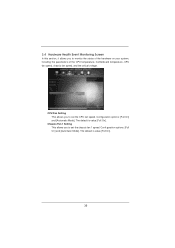
... [Automatic Mode]. CPU Fan Setting This allows you to monitor the status of the hardware on your system, including the parameters of the CPU temperature, motherboard temperature, CPU fan speed, chassis fan speed, and the critical voltage.
... [Automatic Mode]. CPU Fan Setting This allows you to monitor the status of the hardware on your system, including the parameters of the CPU temperature, motherboard temperature, CPU fan speed, chassis fan speed, and the critical voltage.
User Manual
Page 39
... CD Information The Support CD that came with the motherboard contains necessary drivers and useful utilities that the motherboard supports. Chapter 4: Software Support 4.1 Install Operating System This motherboard supports various Microsoft® Windows® operating systems: 7 32bit. Refer to visit ASRock's website at http://www.asrock.com; The CD automatically displays the Main Menu if...
... CD Information The Support CD that came with the motherboard contains necessary drivers and useful utilities that the motherboard supports. Chapter 4: Software Support 4.1 Install Operating System This motherboard supports various Microsoft® Windows® operating systems: 7 32bit. Refer to visit ASRock's website at http://www.asrock.com; The CD automatically displays the Main Menu if...

