
RAID Installation Guide
Page 2
... drive as a single drive but at a sustained data transfer rate. Although RAID 0 function can start to use the onboard RAID Option ROM Utility to configure RAID. 1.1 Introduction to RAID The term "RAID" stands for you to configure RAID functions by using the onboard FastBuild BIOS utility under BIOS environment. After you make a SATA driver diskette, press or to enter BIOS setup to set . RAID 1 (Data Mirroring) RAID 1 is a method combining two or more hard disk drives into one logical unit. AMD BIOS RAID Installation Guide AMD BIOS RAID Installation Guide is an instruction...
... drive as a single drive but at a sustained data transfer rate. Although RAID 0 function can start to use the onboard RAID Option ROM Utility to configure RAID. 1.1 Introduction to RAID The term "RAID" stands for you to configure RAID functions by using the onboard FastBuild BIOS utility under BIOS environment. After you make a SATA driver diskette, press or to enter BIOS setup to set . RAID 1 (Data Mirroring) RAID 1 is a method combining two or more hard disk drives into one logical unit. AMD BIOS RAID Installation Guide AMD BIOS RAID Installation Guide is an instruction...

RAID Installation Guide
Page 8
... the USB port. E. STEP 3.2: Download driver from ASRock's website and unzip the file into your USB flash drive. 8 During system boot, press or key to finish the configuration. C. D. STEP 3.1: Copy RAID driver to a USB flash drive You can choose either STEP 3.1 or STEP 3.2 to enter UEFI setup utility. Click to Tools Easy RAID Installer F. A. Please install the DVD-ROM. B. STEP 4: Windows installation A. Plug a USB drive into the DVD-ROM drive. Go to find the driver inside your USB flash disk. Please download the "SATA Floppy Imaged driver" from ASRock...
... the USB port. E. STEP 3.2: Download driver from ASRock's website and unzip the file into your USB flash drive. 8 During system boot, press or key to finish the configuration. C. D. STEP 3.1: Copy RAID driver to a USB flash drive You can choose either STEP 3.1 or STEP 3.2 to enter UEFI setup utility. Click to Tools Easy RAID Installer F. A. Please install the DVD-ROM. B. STEP 4: Windows installation A. Plug a USB drive into the DVD-ROM drive. Go to find the driver inside your USB flash disk. Please download the "SATA Floppy Imaged driver" from ASRock...

RAID Installation Guide
Page 12
... install the DVD-ROM. E. Please download the "SATA Floppy Imaged driver" from ASRock's website A. Insert the Support CD into your USB flash disk. 12 STEP 2.2: Download driver from ASRock's website and unzip the file into the DVD-ROM drive. H. Click to save to finish the configuration. Plug a USB drive into one of the USB port. C. STEP 2.1: Copy RAID driver to a USB flash drive You can choose either STEP2.1 or STEP2.2 to exit. During system boot, press or key to delete the existing disk...
... install the DVD-ROM. E. Please download the "SATA Floppy Imaged driver" from ASRock's website A. Insert the Support CD into your USB flash disk. 12 STEP 2.2: Download driver from ASRock's website and unzip the file into the DVD-ROM drive. H. Click to save to finish the configuration. Plug a USB drive into one of the USB port. C. STEP 2.1: Copy RAID driver to a USB flash drive You can choose either STEP2.1 or STEP2.2 to exit. During system boot, press or key to delete the existing disk...

User Manual
Page 4
... Specifications 2 1.3 Motherboard Layout 7 1.4 I/O Panel 9 Chapter 2 Installation 11 2.1 Installing the CPU 12 2.2 Installing the CPU Fan and Heatsink 14 2.3 Installing Memory Modules (DIMM) 22 2.4 Expansion Slots (PCI Express Slots) 25 2.5 Jumpers Setup 26 2.6 Onboard Headers and Connectors 27 2.7 CrossFireXTM and Quad CrossFireXTM Operation Guide 32 2.7.1 Installing Two CrossFireXTM-Ready Graphics Cards 32 2.7.2 Driver Installation and Setup 34 2.8 M.2 WiFi/BT Module Installation Guide 35 Chapter 3 Software and Utilities Operation 37 3.1 Installing Drivers 37...
... Specifications 2 1.3 Motherboard Layout 7 1.4 I/O Panel 9 Chapter 2 Installation 11 2.1 Installing the CPU 12 2.2 Installing the CPU Fan and Heatsink 14 2.3 Installing Memory Modules (DIMM) 22 2.4 Expansion Slots (PCI Express Slots) 25 2.5 Jumpers Setup 26 2.6 Onboard Headers and Connectors 27 2.7 CrossFireXTM and Quad CrossFireXTM Operation Guide 32 2.7.1 Installing Two CrossFireXTM-Ready Graphics Cards 32 2.7.2 Driver Installation and Setup 34 2.8 M.2 WiFi/BT Module Installation Guide 35 Chapter 3 Software and Utilities Operation 37 3.1 Installing Drivers 37...
User Manual
Page 7
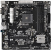
...Pro4/DASH Quick Installation Guide • ASRock AB350M Pro4/DASH Support CD • 1 x I/O Panel Shield • 2 x Serial ATA (SATA) Data Cables (Optional) • 1 x Screw for purchasing ASRock AB350M Pro4/DASH motherboard, a reliable motherboard produced under ASRock's consistently stringent quality control. In this manual occur, the updated version will be subject to quality and endurance. It delivers excellent performance with robust design conforming to ASRock's commitment to change without further notice. Chapter 3 contains the operation guide of the BIOS setup. In case...
...Pro4/DASH Quick Installation Guide • ASRock AB350M Pro4/DASH Support CD • 1 x I/O Panel Shield • 2 x Serial ATA (SATA) Data Cables (Optional) • 1 x Screw for purchasing ASRock AB350M Pro4/DASH motherboard, a reliable motherboard produced under ASRock's consistently stringent quality control. In this manual occur, the updated version will be subject to quality and endurance. It delivers excellent performance with robust design conforming to ASRock's commitment to change without further notice. Chapter 3 contains the operation guide of the BIOS setup. In case...

User Manual
Page 9
... use Athlon 2xxGE series APU, PCIE2 slot will run at x4 mode.)* • 1 x PCI Express 2.0 x16 Slot (PCIE4: x4 mode) * Supports NVMe SSD as boot disks • 2 x PCI Express 2.0 x1 Slots • Supports AMD Quad CrossFireXTM and CrossFireXTM • 1 x M.2 Socket (Key E), supports type 2230 WiFi/BT module Graphics • Integrated AMD RadeonTM Vega Series Graphics in Ryzen Series APU* • Integrated AMD RadeonTM R-Series Graphics in A-series APU* * Actual support may vary by CPU • DirectX 12, Pixel Shader 5.0 • Shared memory default...
... use Athlon 2xxGE series APU, PCIE2 slot will run at x4 mode.)* • 1 x PCI Express 2.0 x16 Slot (PCIE4: x4 mode) * Supports NVMe SSD as boot disks • 2 x PCI Express 2.0 x1 Slots • Supports AMD Quad CrossFireXTM and CrossFireXTM • 1 x M.2 Socket (Key E), supports type 2230 WiFi/BT module Graphics • Integrated AMD RadeonTM Vega Series Graphics in Ryzen Series APU* • Integrated AMD RadeonTM R-Series Graphics in A-series APU* * Actual support may vary by CPU • DirectX 12, Pixel Shader 5.0 • Shared memory default...
User Manual
Page 11
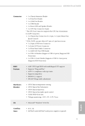
AB350M Pro4/DASH Connector • 1 x Chassis Intrusion Header • 1 x Print Port Header • 1 x COM Port Header • 1 x TPM Header • 1 x Power LED and Speaker Header • 1 x CPU Fan Connector (4-pin) * The CPU Fan Connector supports the CPU fan of maximum 1A (12W) fan power. • 2 x Chassis Fan Connectors (1 x 4-pin, 1 x 3-pin) (Smart Fan Speed Control) * CHA_FAN1 can auto detect if 3-pin or 4-pin fan is in use. • 1 x 24 pin ATX Power Connector • 1 x 8 pin 12V Power Connector • 1 x Front Panel Audio Connector • 1 x AMD LED Fan USB Header &#...
AB350M Pro4/DASH Connector • 1 x Chassis Intrusion Header • 1 x Print Port Header • 1 x COM Port Header • 1 x TPM Header • 1 x Power LED and Speaker Header • 1 x CPU Fan Connector (4-pin) * The CPU Fan Connector supports the CPU fan of maximum 1A (12W) fan power. • 2 x Chassis Fan Connectors (1 x 4-pin, 1 x 3-pin) (Smart Fan Speed Control) * CHA_FAN1 can auto detect if 3-pin or 4-pin fan is in use. • 1 x 24 pin ATX Power Connector • 1 x 8 pin 12V Power Connector • 1 x Front Panel Audio Connector • 1 x AMD LED Fan USB Header &#...

User Manual
Page 14
...-pin DDR4 DIMM Slots (DDR4_A2, DDR4_B2) 5 ATX Power Connector (ATXPWR1) 6 USB 3.1 Gen1 Header (USB3_67) 7 AMD LED Fan USB Header (USB_7) 8 SATA3 Connector (SATA3_3) 9 SATA3 Connector (SATA3_4) 10 SATA3 Connector (SATA3_2) 11 SATA3 Connector (SATA3_1) 12 System Panel Header (PANEL1) 13 Power LED and Speaker Header (SPK_PLED1) 14 Chassis Intrusion Header (CI1) 15 Chassis Fan Connector (CHA_FAN2) 16 USB 2.0 Header (USB_3_4) 17 USB 2.0 Header (USB_5_6) 18 Clear CMOS Jumper (CLRCMOS1) 19 Print Port Header (LPT1) 20 COM Port Header (COM1) 21 TPM Header (TPMS1) 22 Front Panel Audio Header (HD_AUDIO1...
...-pin DDR4 DIMM Slots (DDR4_A2, DDR4_B2) 5 ATX Power Connector (ATXPWR1) 6 USB 3.1 Gen1 Header (USB3_67) 7 AMD LED Fan USB Header (USB_7) 8 SATA3 Connector (SATA3_3) 9 SATA3 Connector (SATA3_4) 10 SATA3 Connector (SATA3_2) 11 SATA3 Connector (SATA3_1) 12 System Panel Header (PANEL1) 13 Power LED and Speaker Header (SPK_PLED1) 14 Chassis Intrusion Header (CI1) 15 Chassis Fan Connector (CHA_FAN2) 16 USB 2.0 Header (USB_3_4) 17 USB 2.0 Header (USB_5_6) 18 Clear CMOS Jumper (CLRCMOS1) 19 Print Port Header (LPT1) 20 COM Port Header (COM1) 21 TPM Header (TPMS1) 22 Front Panel Audio Header (HD_AUDIO1...

User Manual
Page 17
... to avoid damage from static electricity to the motherboard's components, NEVER place your chassis to unplug the power cord before you handle the components. • Hold components by the edges and do not touch the ICs. • Whenever you install motherboard components or change any components, place them on a carpet. AB350M Pro4/DASH Chapter 2 Installation This is a Micro ATX form factor...
... to avoid damage from static electricity to the motherboard's components, NEVER place your chassis to unplug the power cord before you handle the components. • Hold components by the edges and do not touch the ICs. • Whenever you install motherboard components or change any components, place them on a carpet. AB350M Pro4/DASH Chapter 2 Installation This is a Micro ATX form factor...

User Manual
Page 31
PCIE2 (PCIe 3.0 x16 slot) is used for PCI Express x1 lane width cards. Before installing an expansion card, please make necessary hardware settings for PCI Express x4 lane width graphics cards. PCIe slots: PCIE1 (PCIe 2.0 x1 slot) is used for the card before you start the installation. PCIE3 (PCIe 2.0 x1 slot) is used for PCI Express x1 lane width cards. AB350M Pro4/DASH 2.4 Expansion Slots (PCI Express Slots) There are 4 PCI Express slots on the motherboard. PCIe Slot Configurations A-Series APUs PCIE1 PCIE2 PCIE3 PCIE4 x1 x8 x1 x4 Ryzen Series CPUs (Pinnacle Ridge...
PCIE2 (PCIe 3.0 x16 slot) is used for PCI Express x1 lane width cards. Before installing an expansion card, please make necessary hardware settings for PCI Express x4 lane width graphics cards. PCIe slots: PCIE1 (PCIe 2.0 x1 slot) is used for the card before you start the installation. PCIE3 (PCIe 2.0 x1 slot) is used for PCI Express x1 lane width cards. AB350M Pro4/DASH 2.4 Expansion Slots (PCI Express Slots) There are 4 PCI Express slots on the motherboard. PCIe Slot Configurations A-Series APUs PCIE1 PCIE2 PCIE3 PCIE4 x1 x8 x1 x4 Ryzen Series CPUs (Pinnacle Ridge...

User Manual
Page 32
... jumper cap is placed on the pins, the jumper is "Short". The illustration shows a 3-pin jumper whose pin1 and pin2 are setup. Clear CMOS Jumper (CLRMOS1) (see p.7, No. 18) Default Clear CMOS CLRMOS1 allows you need to default setup, please turn off the computer and unplug the power cord from the power supply. If you update the BIOS. After waiting for 5 seconds. Please adjust the BIOS option "Clear Status" to clear the record of previous chassis...
... jumper cap is placed on the pins, the jumper is "Short". The illustration shows a 3-pin jumper whose pin1 and pin2 are setup. Clear CMOS Jumper (CLRMOS1) (see p.7, No. 18) Default Clear CMOS CLRMOS1 allows you need to default setup, please turn off the computer and unplug the power cord from the power supply. If you update the BIOS. After waiting for 5 seconds. Please adjust the BIOS option "Clear Status" to clear the record of previous chassis...
User Manual
Page 33
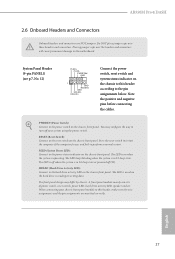
... S3 sleep state. RESET (Reset Switch): Connect to turn off (S5). PLED (System Power LED): Connect to the pin assignments below. AB350M Pro4/DASH 2.6 Onboard Headers and Connectors Onboard headers and connectors are matched correctly. Press the reset switch to restart the computer if the computer freezes and fails to the motherboard. The LED is in S4 sleep state or powered off your chassis front panel module to this header according to the power status indicator on when the hard drive...
... S3 sleep state. RESET (Reset Switch): Connect to turn off (S5). PLED (System Power LED): Connect to the pin assignments below. AB350M Pro4/DASH 2.6 Onboard Headers and Connectors Onboard headers and connectors are matched correctly. Press the reset switch to restart the computer if the computer freezes and fails to the motherboard. The LED is in S4 sleep state or powered off your chassis front panel module to this header according to the power status indicator on when the hard drive...

User Manual
Page 34
.... 11) (SATA3_2: see p.7, No. 10) (SATA3_3: see p.7, No. 8) (SATA3_4: see p.7, No. 9) AMD LED Fan USB Header (4-pin USB_7) (see p.7, No. 7) USB 2.0 Headers (9-pin USB_3_4) (see p.7, No. 16) (9-pin USB_5_6) (see p.7, No. 6) Vbus IntA_PA_SSRXIntA_PA_SSRX+ GND IntA_PA_SSTXIntA_PA_SSTX+ GND IntA_PA_DIntA_PA_D+ Vbus IntA_PB_SSRXIntA_PB_SSRX+ GND IntA_PB_SSTXIntA_PB_SSTX+ GND IntA_PB_DIntA_PB_D+ Dummy 1 There is used for internal storage devices with up to this motherboard. These four SATA3 connectors support SATA data cables for connecting the USB connector on the AMD SR3 Heatsink.
.... 11) (SATA3_2: see p.7, No. 10) (SATA3_3: see p.7, No. 8) (SATA3_4: see p.7, No. 9) AMD LED Fan USB Header (4-pin USB_7) (see p.7, No. 7) USB 2.0 Headers (9-pin USB_3_4) (see p.7, No. 16) (9-pin USB_5_6) (see p.7, No. 6) Vbus IntA_PA_SSRXIntA_PA_SSRX+ GND IntA_PA_SSTXIntA_PA_SSTX+ GND IntA_PA_DIntA_PA_D+ Vbus IntA_PB_SSRXIntA_PB_SSRX+ GND IntA_PB_SSTXIntA_PB_SSTX+ GND IntA_PB_DIntA_PB_D+ Dummy 1 There is used for internal storage devices with up to this motherboard. These four SATA3 connectors support SATA data cables for connecting the USB connector on the AMD SR3 Heatsink.

User Manual
Page 38
... mode. 5. You should only use a AMD certified PSU. Download the drivers from the AMD's website: www.amd.com 3. Please refer to use identical CrossFireXTM-ready graphics cards that are AMD certified. 2. If you to install up to enable CrossFireXTM. 2.7 CrossFireXTM and Quad CrossFireXTM Operation Guide This motherboard supports CrossFireXTM and Quad CrossFireXTM that allows you pair a 12-pipe CrossFireXTM Edition card with this motherboard. Make sure that your power supply...
... mode. 5. You should only use a AMD certified PSU. Download the drivers from the AMD's website: www.amd.com 3. Please refer to use identical CrossFireXTM-ready graphics cards that are AMD certified. 2. If you to install up to enable CrossFireXTM. 2.7 CrossFireXTM and Quad CrossFireXTM Operation Guide This motherboard supports CrossFireXTM and Quad CrossFireXTM that allows you pair a 12-pipe CrossFireXTM Edition card with this motherboard. Make sure that your power supply...
User Manual
Page 40
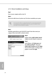
... recommend using this utility to uninstall any VGA drivers installed in the Windows® system tray. Then select Enable AMD CrossFireX and click Apply. Please check AMD's website for details. The Catalyst Uninstaller is an optional download. Step 3 Install the required drivers and CATALYST Control Center then restart your graphics card and click Apply. Please check AMD's website for AMD driver updates. Select the GPU number according to installation. 2.7.2 Driver Installation and Setup Step 1 Power...
... recommend using this utility to uninstall any VGA drivers installed in the Windows® system tray. Then select Enable AMD CrossFireX and click Apply. Please check AMD's website for details. The Catalyst Uninstaller is an optional download. Step 3 Install the required drivers and CATALYST Control Center then restart your graphics card and click Apply. Please check AMD's website for AMD driver updates. Select the GPU number according to installation. 2.7.2 Driver Installation and Setup Step 1 Power...
User Manual
Page 41
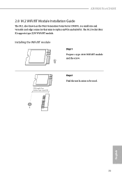
A English 35 PCB Length: 3cm Module Type: Type2230 Step 2 Find the nut location to replace mPCIe and mSATA. Installing the WiFi/BT module Step 1 Prepare a type 2230 WiFi/BT module and the screw. The M.2 Socket (Key E) supports type 2230 WiFi/BT module. AB350M Pro4/DASH 2.8 M.2 WiFi/BT Module Installation Guide The M.2, also known as the Next Generation Form Factor (NGFF), is a small size and versatile card edge connector that aims to be used.
A English 35 PCB Length: 3cm Module Type: Type2230 Step 2 Find the nut location to replace mPCIe and mSATA. Installing the WiFi/BT module Step 1 Prepare a type 2230 WiFi/BT module and the screw. The M.2 Socket (Key E) supports type 2230 WiFi/BT module. AB350M Pro4/DASH 2.8 M.2 WiFi/BT Module Installation Guide The M.2, also known as the Next Generation Form Factor (NGFF), is a small size and versatile card edge connector that aims to be used.
User Manual
Page 43
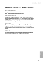
... auto-detected and listed on a specific item then follow the order from top to bottom to display the menu. Click on the support CD driver page. AB350M Pro4/DASH Chapter 3 Software and Utilities Operation 3.1 Installing Drivers The Support CD that comes with the motherboard contains necessary drivers and useful utilities that the motherboard supports. The CD automatically displays the Main Menu if "AUTORUN" is enabled in the Support CD to install those required drivers. Therefore, the drivers you install can work...
... auto-detected and listed on a specific item then follow the order from top to bottom to display the menu. Click on the support CD driver page. AB350M Pro4/DASH Chapter 3 Software and Utilities Operation 3.1 Installing Drivers The Support CD that comes with the motherboard contains necessary drivers and useful utilities that the motherboard supports. The CD automatically displays the Main Menu if "AUTORUN" is enabled in the Support CD to install those required drivers. Therefore, the drivers you install can work...

User Manual
Page 59
Configuration options: [Enabled] and [Disabled]. SVM Mode When this option is set to [Disable] if above issue occurs. Please set this item to enable or disable AMD CPU fTPM. 4.4.1 CPU Configuration AB350M Pro4/DASH Cool 'n' Quiet Use this item to system stability or compatibility issue with some memory modules or power supplies. Please note that enabling this function may reduce CPU voltage and memory frequency, and lead to enable or disable AMD's Cool 'n' QuietTM technology. The default value is [Enabled]. Configuration options: [Enabled] and [Disabled]. 53 English ...
Configuration options: [Enabled] and [Disabled]. SVM Mode When this option is set to [Disable] if above issue occurs. Please set this item to enable or disable AMD CPU fTPM. 4.4.1 CPU Configuration AB350M Pro4/DASH Cool 'n' Quiet Use this item to system stability or compatibility issue with some memory modules or power supplies. Please note that enabling this function may reduce CPU voltage and memory frequency, and lead to enable or disable AMD's Cool 'n' QuietTM technology. The default value is [Enabled]. Configuration options: [Enabled] and [Disabled]. 53 English ...

User Manual
Page 63
Parallel Port Enable or disable the Parallel port. Change Settings Select the address of the Serial port. Device Mode Select the device mode according to your connected device. 57 English 4.4.5 Super IO Configuration AB350M Pro4/DASH Serial Port Enable or disable the Serial port. Serial Port Address Select the address of the Parallel port.
Parallel Port Enable or disable the Parallel port. Change Settings Select the address of the Serial port. Device Mode Select the device mode according to your connected device. 57 English 4.4.5 Super IO Configuration AB350M Pro4/DASH Serial Port Enable or disable the Serial port. Serial Port Address Select the address of the Parallel port.

User Manual
Page 69
...). AB350M Pro4/DASH Opcache Control Enables or disables the Opcache. The valid values for future selections to take effect. To re-enable SMT, a POWER CYCLE is disabled. Redirect scrubber control Control DF::RedirScrubCtrl[EnRedirScrub] Disable DF sync flood propagation Control DF::PIEConfig[DisSyncFloodProp]. Warning: S3 is NOT SUPPORTED on systems where SMT is needed after selecting the 'Auto' option. OC Mode OC1 - 16 cores/3.6GHz on 1.3375V OC2 - 8 cores...
...). AB350M Pro4/DASH Opcache Control Enables or disables the Opcache. The valid values for future selections to take effect. To re-enable SMT, a POWER CYCLE is disabled. Redirect scrubber control Control DF::RedirScrubCtrl[EnRedirScrub] Disable DF sync flood propagation Control DF::PIEConfig[DisSyncFloodProp]. Warning: S3 is NOT SUPPORTED on systems where SMT is needed after selecting the 'Auto' option. OC Mode OC1 - 16 cores/3.6GHz on 1.3375V OC2 - 8 cores...


