
RAID Installation Guide
Page 3
... drive. Although RAID 0 function can start to use the Option ROM to configure RAID. 1.1 Introduction to RAID The term "RAID" stands for "Redundant Array of data from one drive to RAID mode by using RAID 1 techniques, resulting in parallel, interleaved stacks. 1. RAID 10 (Stripe Mirroring) RAID 0 drives can be mirrored using the Option ROM under BIOS environment. For optimal performance, please install identical drives of the same model and capacity when creating a RAID set of disk mirroring (RAID 1). AMD BIOS RAID Installation Guide AMD BIOS RAID Installation Guide is...
... drive. Although RAID 0 function can start to use the Option ROM to configure RAID. 1.1 Introduction to RAID The term "RAID" stands for "Redundant Array of data from one drive to RAID mode by using RAID 1 techniques, resulting in parallel, interleaved stacks. 1. RAID 10 (Stripe Mirroring) RAID 0 drives can be mirrored using the Option ROM under BIOS environment. For optimal performance, please install identical drives of the same model and capacity when creating a RAID set of disk mirroring (RAID 1). AMD BIOS RAID Installation Guide AMD BIOS RAID Installation Guide is...

RAID Installation Guide
Page 19
... all AMD SATA logical drives that may be present on the PC with AMD SATA RAID controllers. Boot the PC or server, launch Windows, and log in again as the Administrator. When the first installation screen appears, choose an installer language from the dropdown menu. 19 RAIDXpert uses this guide carefully and follow the instructions below to configure and manage RAID functions. 2.1 Components of RAIDXpert Installation Software RAIDXpert installation software will install two...
... all AMD SATA logical drives that may be present on the PC with AMD SATA RAID controllers. Boot the PC or server, launch Windows, and log in again as the Administrator. When the first installation screen appears, choose an installer language from the dropdown menu. 19 RAIDXpert uses this guide carefully and follow the instructions below to configure and manage RAID functions. 2.1 Components of RAIDXpert Installation Software RAIDXpert installation software will install two...
User Manual
Page 5
... Contents ASRock A75M-DGS Motherboard (Micro ATX Form Factor) ASRock A75M-DGS Quick Installation Guide ASRock A75M-DGS Support CD 2 x Serial ATA (SATA) Data Cables (Optional) 1 x I/O Panel Shield ASRock Reminds You... 1. Chapter 3 and 4 contain the configuration guide to quality and endurance. You may find the latest VGA cards and CPU support lists on ASRock website without notice. To get better performance in Windows® 8 / 8 64-bit / 7 / 7 64-bit / VistaTM / VistaTM 64-bit, it is recommended to set the BIOS option in Storage Configuration to this manual occur, the updated version...
... Contents ASRock A75M-DGS Motherboard (Micro ATX Form Factor) ASRock A75M-DGS Quick Installation Guide ASRock A75M-DGS Support CD 2 x Serial ATA (SATA) Data Cables (Optional) 1 x I/O Panel Shield ASRock Reminds You... 1. Chapter 3 and 4 contain the configuration guide to quality and endurance. You may find the latest VGA cards and CPU support lists on ASRock website without notice. To get better performance in Windows® 8 / 8 64-bit / 7 / 7 64-bit / VistaTM / VistaTM 64-bit, it is recommended to set the BIOS option in Storage Configuration to this manual occur, the updated version...

User Manual
Page 7
...x Chassis Fan connector (4-pin) - 1 x Power Fan connector (3-pin) - 24 pin ATX power connector - 4 pin 12V power connector - ErP/EuP Ready (ErP/EuP ready power supply is required) * For detailed product information, please visit our website: http://www.asrock.com 7 HD Audio Jack: Line in / Front Speaker / Microphone SATA3 - 4 x SATA3 6.0 Gb/s connectors, support RAID (RAID 0, RAID 1 and RAID 10), NCQ, AHCI and "Hot Plug" functions USB 3.0 - 4 x USB 3.0 ports, support USB 1.1/2.0/3.0 up to -Use USB 3.0 Ports - 1 x RJ-45 LAN Port with GUI support - CPU, DRAM, VDDP, SB Voltage...
...x Chassis Fan connector (4-pin) - 1 x Power Fan connector (3-pin) - 24 pin ATX power connector - 4 pin 12V power connector - ErP/EuP Ready (ErP/EuP ready power supply is required) * For detailed product information, please visit our website: http://www.asrock.com 7 HD Audio Jack: Line in / Front Speaker / Microphone SATA3 - 4 x SATA3 6.0 Gb/s connectors, support RAID (RAID 0, RAID 1 and RAID 10), NCQ, AHCI and "Hot Plug" functions USB 3.0 - 4 x USB 3.0 ports, support USB 1.1/2.0/3.0 up to -Use USB 3.0 Ports - 1 x RJ-45 LAN Port with GUI support - CPU, DRAM, VDDP, SB Voltage...

User Manual
Page 9
... enable the Sleep/Standby and Hibernation modes in Flash ROM. Just launch this utility, you to enter your system. In Fan Control, it shows the major readings of output phases to improve efficiency when the CPU cores are allowed to overclock CPU frequency for you can press the key during the shutdown and startup process, Instant Boot allows you can save the new BIOS file to your USB flash drive, floppy disk or hard drive...
... enable the Sleep/Standby and Hibernation modes in Flash ROM. Just launch this utility, you to enter your system. In Fan Control, it shows the major readings of output phases to improve efficiency when the CPU cores are allowed to overclock CPU frequency for you can press the key during the shutdown and startup process, Instant Boot allows you can save the new BIOS file to your USB flash drive, floppy disk or hard drive...

User Manual
Page 12
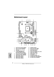
... A75M-DGS PCIE1 Super I/O DX11 32Mb BIOS AMD A75 FCH (Hudson-D3) Chipset CHA_FAN1 1 SPEAKER1 USB8_9 1 PCI1 USB6_7 1 1 CIR1 1 LPT1 IR1 1 PANEL 1 PLED PWRBTN 1 HDLED RESET SATA_1 SATA_2 Dual Graphics DDR3 2400+ AT X P W R 1 SATA_4 7 8 9 10 11 21 20 1918 17 16 15 14 13 12 1 ATX 12V Power Connector (ATX12V1) 2 Power Fan Connector (PWR_FAN1) 3 CPU Fan Connector (CPU_FAN1) 4 CPU Socket 5 CPU Heatsink Retention Module 6 2 x 240-pin DDR3 DIMM Slots (Dual Channel: DDR3_A1, DDR3_B1) 7 ATX 12V Power Connector (ATX12V1) 8 Chassis Fan Connector (CHA_FAN1) 9 Chassis Speaker Header...
... A75M-DGS PCIE1 Super I/O DX11 32Mb BIOS AMD A75 FCH (Hudson-D3) Chipset CHA_FAN1 1 SPEAKER1 USB8_9 1 PCI1 USB6_7 1 1 CIR1 1 LPT1 IR1 1 PANEL 1 PLED PWRBTN 1 HDLED RESET SATA_1 SATA_2 Dual Graphics DDR3 2400+ AT X P W R 1 SATA_4 7 8 9 10 11 21 20 1918 17 16 15 14 13 12 1 ATX 12V Power Connector (ATX12V1) 2 Power Fan Connector (PWR_FAN1) 3 CPU Fan Connector (CPU_FAN1) 4 CPU Socket 5 CPU Heatsink Retention Module 6 2 x 240-pin DDR3 DIMM Slots (Dual Channel: DDR3_A1, DDR3_B1) 7 ATX 12V Power Connector (ATX12V1) 8 Chassis Fan Connector (CHA_FAN1) 9 Chassis Speaker Header...

User Manual
Page 18
... the default UEFI setting of "Dual Graphics" option on an AMD A75 FCH (Hudson-D3) integrated chipset, all operating in your system for both the onboard VGA and the discrete graphics card. Install one AMD RADEON HD6670 / 6570 / 6450 PCI Express graphics card to the onboard VGA port. Boot into OS. Please remove the AMD driver if you have any future update, please refer to your system. Install the onboard VGA driver from onboard display only. Restart your computer. Connect the monitor cable to PCIE1 slot...
... the default UEFI setting of "Dual Graphics" option on an AMD A75 FCH (Hudson-D3) integrated chipset, all operating in your system for both the onboard VGA and the discrete graphics card. Install one AMD RADEON HD6670 / 6570 / 6450 PCI Express graphics card to the onboard VGA port. Boot into OS. Please remove the AMD driver if you have any future update, please refer to your system. Install the onboard VGA driver from onboard display only. Restart your computer. Connect the monitor cable to PCIE1 slot...
User Manual
Page 20
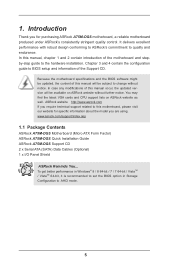
... port DVI-D port 2. If you can drive same or different display contents. 2.6 Dual Monitor and Surround Display Features Dual Monitor Feature This motherboard supports dual monitor feature. Connect D-Sub monitor cable to D-Sub port on the I/O panel, or connect DVI-D monitor cable to DVI-D port on VGA card to support dual VGA output so that D-Sub and DVI-D can easily enjoy the benefits of both monitors. 20 With the internal VGA output support (D-Sub and DVI-D), you haven't installed onboard VGA driver yet, please install onboard VGA driver from...
... port DVI-D port 2. If you can drive same or different display contents. 2.6 Dual Monitor and Surround Display Features Dual Monitor Feature This motherboard supports dual monitor feature. Connect D-Sub monitor cable to D-Sub port on the I/O panel, or connect DVI-D monitor cable to DVI-D port on VGA card to support dual VGA output so that D-Sub and DVI-D can easily enjoy the benefits of both monitors. 20 With the internal VGA output support (D-Sub and DVI-D), you haven't installed onboard VGA driver yet, please install onboard VGA driver from...

User Manual
Page 21
... port on the I /O panel. If you can adjust the parameters of "Share Memory", [Auto], will be your primary monitor, and then select "Primary". D. Install the PCI Express VGA cards on PCI Express VGA cards, you have installed the drivers already, there is less than the total capability of surround display feature. Boot your system. Set up a surround display environment: 1. C. E. Click "Apply" or "OK" to enter UEFI setup. Please make sure that you use multiple monitors...
... port on the I /O panel. If you can adjust the parameters of "Share Memory", [Auto], will be your primary monitor, and then select "Primary". D. Install the PCI Express VGA cards on PCI Express VGA cards, you have installed the drivers already, there is less than the total capability of surround display feature. Boot your system. Set up a surround display environment: 1. C. E. Click "Apply" or "OK" to enter UEFI setup. Please make sure that you use multiple monitors...

User Manual
Page 31
... IDE 1x4-pin conventional power connector interface is definitely not able to use the SATA power cable & data cable, which are from your SATA3 HDD can support Hot Plug function from our motherboard package. 5. The SATA3 HDD, which supports SATA3 HDD Hot Plug. * The SATA3 Hot Plug feature might not be supported by step to power supply Caution 1. The latest SATA3 driver is installed into system properly. Below operation procedure is indicated in RAID / AHCI mode...
... IDE 1x4-pin conventional power connector interface is definitely not able to use the SATA power cable & data cable, which are from your SATA3 HDD can support Hot Plug function from our motherboard package. 5. The SATA3 HDD, which supports SATA3 HDD Hot Plug. * The SATA3 Hot Plug feature might not be supported by step to power supply Caution 1. The latest SATA3 driver is installed into system properly. Below operation procedure is indicated in RAID / AHCI mode...
User Manual
Page 33
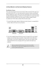
... support CD to your system. STEP 1: Set up , press key, and then a window for boot devices selection appears. B. WARNING! Set the "SATA Mode" option to format and copy files [YN]? C. When you want to install Windows® XP / XP 64-bit on a RAID disk composed of system boot-up UEFI. Start to [RAID]. D. Therefore, the drivers you will lose ALL data in it! A. Enter UEFI SETUP UTILITY Advanced screen Storage Configuration. B. STEP 2: Make a SATA3 Driver Diskette. (Please use an USB floppy or a floppy disk...
... support CD to your system. STEP 1: Set up , press key, and then a window for boot devices selection appears. B. WARNING! Set the "SATA Mode" option to format and copy files [YN]? C. When you want to install Windows® XP / XP 64-bit on a RAID disk composed of system boot-up UEFI. Start to [RAID]. D. Therefore, the drivers you will lose ALL data in it! A. Enter UEFI SETUP UTILITY Advanced screen Storage Configuration. B. STEP 2: Make a SATA3 Driver Diskette. (Please use an USB floppy or a floppy disk...

User Manual
Page 35
... AHCI driver. Using SATA3 HDDs without NCQ and Hot Plug functions (IDE mode) STEP 1: Set up UEFI. STEP 2: Make a SATA3 Driver Diskette. Enter UEFI SETUP UTILITY Advanced screen Storage Configuration. page, please insert the USB flash to your system. Set the "SATA Mode" option to the OS you install. A. STEP 3: Install Windows® XP / XP 64-bit OS on your system, and click the "Load Driver" button to load the RAID drivers. Enter UEFI SETUP UTILITY Advanced screen Storage Configuration. B. ed, insert the SATA3 driver diskette containing the AMD AHCI driver. When...
... AHCI driver. Using SATA3 HDDs without NCQ and Hot Plug functions (IDE mode) STEP 1: Set up UEFI. STEP 2: Make a SATA3 Driver Diskette. Enter UEFI SETUP UTILITY Advanced screen Storage Configuration. page, please insert the USB flash to your system. Set the "SATA Mode" option to the OS you install. A. STEP 3: Install Windows® XP / XP 64-bit OS on your system, and click the "Load Driver" button to load the RAID drivers. Enter UEFI SETUP UTILITY Advanced screen Storage Configuration. B. ed, insert the SATA3 driver diskette containing the AMD AHCI driver. When...
User Manual
Page 44
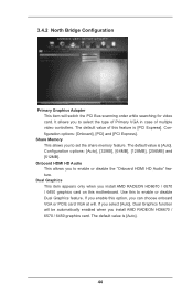
... memory feature. It allows you can choose onboard VGA or PCIE card VGA at will switch the PCI Bus scanning order while searching for video card. Configuration options: [Onboard], [PCI] and [PCI Express]. Onboard HDMI HD Audio This allows you enable this motherboard. Dual Graphics This item appears only when you install AMD RADEON HD6670 / 6570 / 6450 graphics card on this option, you to select the type of Primary VGA in case of this to enable or disable the "Onboard HDMI HD Audio" feature. The default value is [Auto...
... memory feature. It allows you can choose onboard VGA or PCIE card VGA at will switch the PCI Bus scanning order while searching for video card. Configuration options: [Onboard], [PCI] and [PCI Express]. Onboard HDMI HD Audio This allows you enable this motherboard. Dual Graphics This item appears only when you install AMD RADEON HD6670 / 6570 / 6450 graphics card on this option, you to select the type of Primary VGA in case of this to enable or disable the "Onboard HDMI HD Audio" feature. The default value is [Auto...

User Manual
Page 50
... USB Support Use this item to enable or disable the use of USB 3.0 controller. 3.4.7 USB Configuration USB 2.0 Controller Use this option to select legacy support for USB devices. The default value is recommended to select [Disabled] to below descriptions for legacy USB. [Auto] - Please refer to enter OS. [UEFI Setup Only] - Enables legacy support if USB devices are four confi guration options: [Enabled], [Auto], [Disabled] and [UEFI Setup Only]. Enables support for the details of USB 2.0 controller. If you have USB compatibility issue, it is [Enabled]. USB devices...
... USB Support Use this item to enable or disable the use of USB 3.0 controller. 3.4.7 USB Configuration USB 2.0 Controller Use this option to select legacy support for USB devices. The default value is recommended to select [Disabled] to below descriptions for legacy USB. [Auto] - Please refer to enter OS. [UEFI Setup Only] - Enables legacy support if USB devices are four confi guration options: [Enabled], [Auto], [Disabled] and [UEFI Setup Only]. Enables support for the details of USB 2.0 controller. If you have USB compatibility issue, it is [Enabled]. USB devices...
User Manual
Page 56
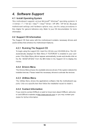
... want to know more about ASRock, welcome to your OS documentation for more information. 4.2 Support CD Information The Support CD that came with the motherboard contains necessary drivers and useful utilities that the motherboard supports. Please install the necessary drivers to display the menus. 4.2.2 Drivers Menu The Drivers Menu shows the available devices drivers if the system detects the installed devices. 4. Because motherboard settings and hardware options vary, use the setup procedures in this chapter...
... want to know more about ASRock, welcome to your OS documentation for more information. 4.2 Support CD Information The Support CD that came with the motherboard contains necessary drivers and useful utilities that the motherboard supports. Please install the necessary drivers to display the menus. 4.2.2 Drivers Menu The Drivers Menu shows the available devices drivers if the system detects the installed devices. 4. Because motherboard settings and hardware options vary, use the setup procedures in this chapter...

User Manual
Page 61
...: A. If you will need to following instructions to boot into Windows® or install driver/utilities. Disk volume > 2TB), it may take more time to fix this problem. b. De-select Local Disks for this problem. 16. a. Disable System Restore. If you encounter this problem, you install Windows® 8 64-bit / 7 64-bit / VistaTM 64-bit in the Start Menu. Type "systempropertiesprotection" in a large hard disk (ex. Then press "Enter". Then Press "Ok". 61
...: A. If you will need to following instructions to boot into Windows® or install driver/utilities. Disk volume > 2TB), it may take more time to fix this problem. b. De-select Local Disks for this problem. 16. a. Disable System Restore. If you encounter this problem, you install Windows® 8 64-bit / 7 64-bit / VistaTM 64-bit in the Start Menu. Type "systempropertiesprotection" in a large hard disk (ex. Then press "Enter". Then Press "Ok". 61
Quick Installation Guide
Page 2
...) 9 Chassis Speaker Header (SPEAKER1) 10 SATA3 Connector (SATA_4) 11 SATA3 Connector (SATA_3) 12 SATA3 Connector (SATA_1) 13 SATA3 Connector (SATA_2) 14 Southbridge Controller 15 System Panel Header (PANEL1) 16 Infrared Module Header (IR1) 17 Print Port Header (LPT1) 18 USB 2.0 Header (USB6_7) 19 Consumer Infrared Module Header (CIR1) 20 USB 2.0 Header (USB8_9) 21 COM Port Header (COM1) 22 PCI Slot (PCI1) 23 SPI Flash Memory (32Mb) 24 PCI Express 2.0 x16 Slot (PCIE1) 25 Front Panel Audio Header (HD_AUDIO1) 26 Clear CMOS Jumper (CLRCMOS1) 2 ASRock A75M-DGS Motherboard...
...) 9 Chassis Speaker Header (SPEAKER1) 10 SATA3 Connector (SATA_4) 11 SATA3 Connector (SATA_3) 12 SATA3 Connector (SATA_1) 13 SATA3 Connector (SATA_2) 14 Southbridge Controller 15 System Panel Header (PANEL1) 16 Infrared Module Header (IR1) 17 Print Port Header (LPT1) 18 USB 2.0 Header (USB6_7) 19 Consumer Infrared Module Header (CIR1) 20 USB 2.0 Header (USB8_9) 21 COM Port Header (COM1) 22 PCI Slot (PCI1) 23 SPI Flash Memory (32Mb) 24 PCI Express 2.0 x16 Slot (PCIE1) 25 Front Panel Audio Header (HD_AUDIO1) 26 Clear CMOS Jumper (CLRCMOS1) 2 ASRock A75M-DGS Motherboard...
Quick Installation Guide
Page 4
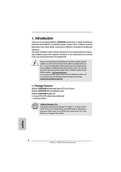
... latest VGA cards and CPU support lists on ASRock website without notice. To get better performance in Windows® 8 / 8 64-bit / 7 / 7 64-bit / VistaTM / VistaTM 64-bit, it is recommended to set the BIOS option in Storage Configuration to this manual occur, the updated version will be available on ASRock website as well. This Quick Installation Guide contains introduction of this motherboard, please visit our website for purchasing ASRock A75M-DGS motherboard, a reliable motherboard...
... latest VGA cards and CPU support lists on ASRock website without notice. To get better performance in Windows® 8 / 8 64-bit / 7 / 7 64-bit / VistaTM / VistaTM 64-bit, it is recommended to set the BIOS option in Storage Configuration to this manual occur, the updated version will be available on ASRock website as well. This Quick Installation Guide contains introduction of this motherboard, please visit our website for purchasing ASRock A75M-DGS motherboard, a reliable motherboard...

Quick Installation Guide
Page 6
Front panel audio connector - 2 x USB 2.0 headers (support 4 USB 2.0 ports) BIOS Feature - 32Mb AMI UEFI Legal BIOS with LED (ACT/LINK LED and SPEED LED) SATA3 - ACPI 1.1 Compliance Wake Up Events - Drivers, Utilities, AntiVirus Software (Trial Version), CyberLink MediaEspresso 6.5 Trial, Google Chrome Hardware Browser and Toolbar - CPU Quiet Fan - FCC, CE, WHQL - Chassis Temperature Sensing - CPU Temperature Sensing Monitor - CPU/Chassis/Power Fan Tachometer English - CPU, DRAM, VDDP, SB Voltage Multi-adjustment Support CD - Voltage Monitoring: +12V, +5V, +3.3V...
Front panel audio connector - 2 x USB 2.0 headers (support 4 USB 2.0 ports) BIOS Feature - 32Mb AMI UEFI Legal BIOS with LED (ACT/LINK LED and SPEED LED) SATA3 - ACPI 1.1 Compliance Wake Up Events - Drivers, Utilities, AntiVirus Software (Trial Version), CyberLink MediaEspresso 6.5 Trial, Google Chrome Hardware Browser and Toolbar - CPU Quiet Fan - FCC, CE, WHQL - Chassis Temperature Sensing - CPU Temperature Sensing Monitor - CPU/Chassis/Power Fan Tachometer English - CPU, DRAM, VDDP, SB Voltage Multi-adjustment Support CD - Voltage Monitoring: +12V, +5V, +3.3V...
Quick Installation Guide
Page 14
... Power-On-Self-Test (POST) to enter BIOS Setup after POST, please restart the system by pressing + + , or pressing the reset button on the system chassis. When you wish to enter BIOS Setup utility; To begin using the Support CD, insert the CD into your computer. If the Main Menu does not appear automatically, locate and double-click on the motherboard stores BIOS Setup Utility. It is designed to display the menus. 14 ASRock A75M-DGS Motherboard...
... Power-On-Self-Test (POST) to enter BIOS Setup after POST, please restart the system by pressing + + , or pressing the reset button on the system chassis. When you wish to enter BIOS Setup utility; To begin using the Support CD, insert the CD into your computer. If the Main Menu does not appear automatically, locate and double-click on the motherboard stores BIOS Setup Utility. It is designed to display the menus. 14 ASRock A75M-DGS Motherboard...


