
RAID Installation Guide
Page 6
...contains a failed physical drive. For RAID levels 1, 5, and 10, two or more physical drives in components of disk drives. The AMD motherboard port ID number to enter the Utility. Status - An identification number assigned to it . But the logical drive has lost fault tolerance. ...logical drive and copy your data to it displays pertinent information about the RAID logical drives that monitors the condition of the AMD motherboard. Critical - The logical drive is still operational, meaning you cannot read and write data to the Self-Monitoring, Analysis and Reporting...
...contains a failed physical drive. For RAID levels 1, 5, and 10, two or more physical drives in components of disk drives. The AMD motherboard port ID number to enter the Utility. Status - An identification number assigned to it . But the logical drive has lost fault tolerance. ...logical drive and copy your data to it displays pertinent information about the RAID logical drives that monitors the condition of the AMD motherboard. Critical - The logical drive is still operational, meaning you cannot read and write data to the Self-Monitoring, Analysis and Reporting...

RAID Installation Guide
Page 8
... Port: ID - You can use unassigned drives to see the View Drive Assignments screen. The total number of ports depends on the motherboard and whether a port multiplier is one logical drive composed of the physical drive. 1.6 Viewing Drive Assignments From the Main Menu screen, ...press 1 to create a new logical drive. Shows the AMD motherboard port ID number to which a particular physical drive is a portion of two physical drives. Capabilities - The type and speed of each physical...
... Port: ID - You can use unassigned drives to see the View Drive Assignments screen. The total number of ports depends on the motherboard and whether a port multiplier is one logical drive composed of the physical drive. 1.6 Viewing Drive Assignments From the Main Menu screen, ...press 1 to create a new logical drive. Shows the AMD motherboard port ID number to which a particular physical drive is a portion of two physical drives. Capabilities - The type and speed of each physical...

User Manual
Page 2
... and to the owners' benefit, without intent to change without written consent of ASRock Inc. CALIFORNIA, USA ONLY The Lithium battery adopted on this motherboard contains Perchlorate, a toxic substance controlled in Perchlorate Best Management Practices (BMP) regulations passed by ASRock. Products and corporate names appearing in this manual may or may apply, see...
... and to the owners' benefit, without intent to change without written consent of ASRock Inc. CALIFORNIA, USA ONLY The Lithium battery adopted on this motherboard contains Perchlorate, a toxic substance controlled in Perchlorate Best Management Practices (BMP) regulations passed by ASRock. Products and corporate names appearing in this manual may or may apply, see...

User Manual
Page 3
... (DIMM 16 2.4 Expansion Slots (PCI and PCI Express Slots 17 2.5 Dual Graphics Operation Guide 18 2.6 Dual Monitor and Surround Display Features 20 2.7 ASRock Smart Remote Installation Guide 23 2.8 Jumpers Setup 25 2.9 Onboard Headers and Connectors 26 2.10 Serial ATA3 (SATA3) Hard Disks Installation 30 2.11 Hot...Installing Windows® 8 / 8 64-bit / 7 / 7 64-bit / VistaTM / VistaTM 64-bit Without RAID Functions 36 3 Introduction 5 1.1 Package Contents 5 1.2 Specifications 6 1.3 Unique Features 9 1.4 Motherboard Layout 12 1.5 I/O Panel 13 2. Contents 1.
... (DIMM 16 2.4 Expansion Slots (PCI and PCI Express Slots 17 2.5 Dual Graphics Operation Guide 18 2.6 Dual Monitor and Surround Display Features 20 2.7 ASRock Smart Remote Installation Guide 23 2.8 Jumpers Setup 25 2.9 Onboard Headers and Connectors 26 2.10 Serial ATA3 (SATA3) Hard Disks Installation 30 2.11 Hot...Installing Windows® 8 / 8 64-bit / 7 / 7 64-bit / VistaTM / VistaTM 64-bit Without RAID Functions 36 3 Introduction 5 1.1 Package Contents 5 1.2 Specifications 6 1.3 Unique Features 9 1.4 Motherboard Layout 12 1.5 I/O Panel 13 2. Contents 1.
User Manual
Page 5
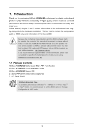
... you are using. Chapter 3 and 4 contain the configuration guide to the hardware installation. ASRock website http://www.asrock.com If you require technical support related to AHCI mode. 5 www.asrock.com/support/index.asp 1.1 Package Contents ASRock A75M-DGS Motherboard (Micro ATX Form Factor) ASRock A75M-DGS Quick Installation Guide ASRock A75M-DGS Support CD 2 x Serial ATA (SATA) Data Cables (Optional) 1 x I/O Panel Shield...
... you are using. Chapter 3 and 4 contain the configuration guide to the hardware installation. ASRock website http://www.asrock.com If you require technical support related to AHCI mode. 5 www.asrock.com/support/index.asp 1.1 Package Contents ASRock A75M-DGS Motherboard (Micro ATX Form Factor) ASRock A75M-DGS Quick Installation Guide ASRock A75M-DGS Support CD 2 x Serial ATA (SATA) Data Cables (Optional) 1 x I/O Panel Shield...
User Manual
Page 8
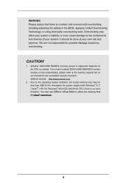
... such limitation. If you adopt. We are not responsible for the compatible memory modules. Due to the memory support list on this motherboard, please refer to the operating system limitation, the actual memory size may affect your system. It should be less than 4GB for ...caused by overclocking. WARNING Please realize that Windows® cannot use. 8 Overclocking may be done at your own risk and expense. ASRock website http://www.asrock.com 2. For Windows® 64-bit OS with overclocking, including adjusting the setting in the BIOS, applying Untied Overclocking Technology, ...
... such limitation. If you adopt. We are not responsible for the compatible memory modules. Due to the memory support list on this motherboard, please refer to the operating system limitation, the actual memory size may affect your system. It should be less than 4GB for ...caused by overclocking. WARNING Please realize that Windows® cannot use. 8 Overclocking may be done at your own risk and expense. ASRock website http://www.asrock.com 2. For Windows® 64-bit OS with overclocking, including adjusting the setting in the BIOS, applying Untied Overclocking Technology, ...

User Manual
Page 12
1.4 Motherboard Layout 1 23 4 5 6 PS2 Mouse PS2 Keyboard ATX12V1 PWR_FAN1 CPU_FAN1 Fast LAN X Fast RAM X VGA1 DDR3_B1 (64 bit, 240-pin module) SATA_3 DDR3_A1 (64 bit, 240-... IN USB 3.0 T: USB2 B: USB3 USB 3.0 T: USB4 B: USB5 USB 2.0 T: USB0 B: USB1 HD_AUDIO1 LAN AUDIO CODEC COM1 1 RJ-45 LAN 1 ErP/EuP Ready RoHS CMOS BATTERY 1 CLRCMOS1 A75M-DGS PCIE1 Super I/O DX11 32Mb BIOS AMD A75 FCH (Hudson-D3) Chipset CHA_FAN1 1 SPEAKER1 USB8_9 1 PCI1 USB6_7 1 1 CIR1 1 LPT1 IR1 1 PANEL 1 PLED PWRBTN 1 HDLED RESET SATA_1...
1.4 Motherboard Layout 1 23 4 5 6 PS2 Mouse PS2 Keyboard ATX12V1 PWR_FAN1 CPU_FAN1 Fast LAN X Fast RAM X VGA1 DDR3_B1 (64 bit, 240-pin module) SATA_3 DDR3_A1 (64 bit, 240-... IN USB 3.0 T: USB2 B: USB3 USB 3.0 T: USB4 B: USB5 USB 2.0 T: USB0 B: USB1 HD_AUDIO1 LAN AUDIO CODEC COM1 1 RJ-45 LAN 1 ErP/EuP Ready RoHS CMOS BATTERY 1 CLRCMOS1 A75M-DGS PCIE1 Super I/O DX11 32Mb BIOS AMD A75 FCH (Hudson-D3) Chipset CHA_FAN1 1 SPEAKER1 USB8_9 1 PCI1 USB6_7 1 1 CIR1 1 LPT1 IR1 1 PANEL 1 PLED PWRBTN 1 HDLED RESET SATA_1...

User Manual
Page 14
... over-tighten the screws! Hold components by the edges and do so may damage the motherboard. 14 When placing screws into it on the carpet or the like. Before you install the motherboard, study the configuration of the following precautions before you install or remove any component, place... it . To avoid damaging the motherboard components due to static electricity, NEVER place your chassis to ensure that the motherboard fits into the screw holes to secure the motherboard to do not touch the ICs. 4. Unplug the power cord from the...
... over-tighten the screws! Hold components by the edges and do so may damage the motherboard. 14 When placing screws into it on the carpet or the like. Before you install the motherboard, study the configuration of the following precautions before you install or remove any component, place... it . To avoid damaging the motherboard components due to static electricity, NEVER place your chassis to ensure that the motherboard fits into the screw holes to secure the motherboard to do not touch the ICs. 4. Unplug the power cord from the...

User Manual
Page 15
... is in good contact with a small triangle. Carefully insert the CPU into the socket until it is locked. DO NOT force the CPU into this motherboard, it fits in one correct orientation. Then connect the CPU fan to improve heat dissipation. You also need to spray thermal grease between the CPU...
... is in good contact with a small triangle. Carefully insert the CPU into the socket until it is locked. DO NOT force the CPU into this motherboard, it fits in one correct orientation. Then connect the CPU fan to improve heat dissipation. You also need to spray thermal grease between the CPU...

User Manual
Page 16
... clips at both ends fully snap back in one memory module or two non-identical memory modules, it will cause permanent damage to the motherboard and the DIMM if you always need to install two identical (the same brand, speed, size and chiptype) memory modules in the DDR3... DDR or DDR2 memory module into the slot at single channel mode. 1. For dual channel configuration, you force the DIMM into DDR3 slot;otherwise, this motherboard and DIMM may be damaged. 2. Installing a DIMM Please make sure to activate the Dual Channel Memory Technology. Step 3. Step 1. It will operate at...
... clips at both ends fully snap back in one memory module or two non-identical memory modules, it will cause permanent damage to the motherboard and the DIMM if you always need to install two identical (the same brand, speed, size and chiptype) memory modules in the DDR3... DDR or DDR2 memory module into the slot at single channel mode. 1. For dual channel configuration, you force the DIMM into DDR3 slot;otherwise, this motherboard and DIMM may be damaged. 2. Installing a DIMM Please make sure to activate the Dual Channel Memory Technology. Step 3. Step 1. It will operate at...

User Manual
Page 17
Step 2. Keep the screws for later use . Step 6. Black) is completely seated on this motherboard. Remove the bracket facing the slot that you start the installation. Align the card connector with screws. 2.4 Expansion Slots (PCI and PCI Express Slots) There ... make necessary hardware settings for PCI Express x16 lane width graphics cards. Replace the system cover. 17 Step 5. Remove the system unit cover (if your motherboard is used for the card before you intend to install expansion cards that the power supply is switched off or the power cord is 1 PCI...
Step 2. Keep the screws for later use . Step 6. Black) is completely seated on this motherboard. Remove the bracket facing the slot that you start the installation. Align the card connector with screws. 2.4 Expansion Slots (PCI and PCI Express Slots) There ... make necessary hardware settings for PCI Express x16 lane width graphics cards. Replace the system cover. 17 Step 5. Remove the system unit cover (if your motherboard is used for the card before you intend to install expansion cards that the power supply is switched off or the power cord is 1 PCI...

User Manual
Page 18
... refer to our website for further information. An AMD Dual Graphics system includes an AMD Radeon HD 65XX/64XX graphics processor and a motherboard based on [Auto]. Connect the monitor cable to below PCI Express graphics card support list for AMD Dual Graphics. Click "AMD VISION... Engine Control Center" to PCIE1 slot (black). Step 6. 2.5 AMD Dual Graphics Operation Guide This motherboard supports AMD Dual Graphics feature. Currently, AMD Dual Graphics Technology is only supported with Windows® 8 / 7 OS, and is not available with...
... refer to our website for further information. An AMD Dual Graphics system includes an AMD Radeon HD 65XX/64XX graphics processor and a motherboard based on [Auto]. Connect the monitor cable to below PCI Express graphics card support list for AMD Dual Graphics. Click "AMD VISION... Engine Control Center" to PCIE1 slot (black). Step 6. 2.5 AMD Dual Graphics Operation Guide This motherboard supports AMD Dual Graphics feature. Currently, AMD Dual Graphics Technology is only supported with Windows® 8 / 7 OS, and is not available with...
User Manual
Page 20
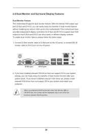
.... Connect D-Sub monitor cable to D-Sub port on the I /O panel, or connect DVI-D monitor cable to this motherboard. 2.6 Dual Monitor and Surround Display Features Dual Monitor Feature This motherboard supports dual monitor feature. This motherboard also provides independent display controllers for D-Sub and DVI-D to your system and restart your system boots. D-Sub...
.... Connect D-Sub monitor cable to D-Sub port on the I /O panel, or connect DVI-D monitor cable to this motherboard. 2.6 Dual Monitor and Surround Display Features Dual Monitor Feature This motherboard supports dual monitor feature. This motherboard also provides independent display controllers for D-Sub and DVI-D to your system and restart your system boots. D-Sub...

User Manual
Page 21
... enjoy the benefits of the multi-monitor according to your system. E. Click "Apply" or "OK" to this monitor". Click "Extend my Windows desktop onto this motherboard. 4. Boot your system. For Windows® XP / XP 64-bit OS: Right click the desktop, choose "Properties", and select the "Settings" tab so that the... procedures for the second monitor. D. Please make sure that you use multiple monitors with your primary monitor, and then select "Primary". Surround Display Feature This motherboard supports surround display upgrade.
... enjoy the benefits of the multi-monitor according to your system. E. Click "Apply" or "OK" to this monitor". Click "Extend my Windows desktop onto this motherboard. 4. Boot your system. For Windows® XP / XP 64-bit OS: Right click the desktop, choose "Properties", and select the "Settings" tab so that the... procedures for the second monitor. D. Please make sure that you use multiple monitors with your primary monitor, and then select "Primary". Surround Display Feature This motherboard supports surround display upgrade.

User Manual
Page 22
C. Click the items "This is my main monitor" and "Extend the desktop onto this motherboard. Use Surround Display. HDCP is a copy protection scheme to use HDCP function with high-definition HDCP encryption contents. such as a computer, DVD player or set...bit OS: Right click the desktop, choose "Personalize", and select the "Display Settings" tab so that you can enjoy the superior display quality with this motherboard, you need to protect the integrity of content as it is highly recommended that the HDTV or LCD monitor you move items from one monitor...
C. Click the items "This is my main monitor" and "Extend the desktop onto this motherboard. Use Surround Display. HDCP is a copy protection scheme to use HDCP function with high-definition HDCP encryption contents. such as a computer, DVD player or set...bit OS: Right click the desktop, choose "Personalize", and select the "Display Settings" tab so that you can enjoy the superior display quality with this motherboard, you need to protect the integrity of content as it is highly recommended that the HDTV or LCD monitor you move items from one monitor...

User Manual
Page 23
...located next to enter BIOS Setup Utility. Press or to the USB 2.0 header on ASRock motherboard. Install Multi-Angle CIR Receiver to the USB_PWR USB 2.0 header (as below procedures for ASRock motherboard with CIR header. Please refer to the other front USB port then try again. Step4.... Enter Windows. Step1. Connect the front USB cable to the front USB port. Step5. 2.7 ASRock Smart Remote Installation Guide ASRock Smart Remote is listed at [...
...located next to enter BIOS Setup Utility. Press or to the USB 2.0 header on ASRock motherboard. Install Multi-Angle CIR Receiver to the USB_PWR USB 2.0 header (as below procedures for ASRock motherboard with CIR header. Please refer to the other front USB port then try again. Step4.... Enter Windows. Step1. Connect the front USB cable to the front USB port. Step5. 2.7 ASRock Smart Remote Installation Guide ASRock Smart Remote is listed at [...

User Manual
Page 24
...Plug function. 3 CIR sensors in different angles 1. Please install it on the market. 3. When the CIR function is compatible with most of ASRock motherboards. Multi-Angle CIR Receiver is only supported by some of the chassis on the rear panel. Multi-Angle CIR Receiver can support CIR function.... Please refer to connect it before you boot the system. * ASRock Smart Remote is used for the motherboard support list: http://www.asrock.com 24 Only one of the front USB port can receive the multi-direction infrared signals (top, down and...
...Plug function. 3 CIR sensors in different angles 1. Please install it on the market. 3. When the CIR function is compatible with most of ASRock motherboards. Multi-Angle CIR Receiver is only supported by some of the chassis on the rear panel. Multi-Angle CIR Receiver can support CIR function.... Please refer to connect it before you boot the system. * ASRock Smart Remote is used for the motherboard support list: http://www.asrock.com 24 Only one of the front USB port can receive the multi-direction infrared signals (top, down and...

User Manual
Page 26
The current SATA3 interface allows up to the SATA3 hard disk or the SATA3 connector on this motherboard. Print Port Header (25-pin LPT1) (see p.12, No. 10) SATA_3 SATA_1 SATA_2 SATA_4 These four Serial ATA3 (SATA3) connectors support SATA ... be connected to 6.0 Gb/s data transfer rate. Placing jumper caps over these headers and connectors. Serial ATA (SATA) Data Cable (Optional) Either end of the motherboard! USB 2.0 Headers (9-pin USB6_7) (see p.12 No. 18) (9-pin USB8_9) (see p.12 No. 20) USB_PWR P-9 P+9 GND DUMMY 1 GND P+8 P-8 USB_PWR Besides two default USB ...
The current SATA3 interface allows up to the SATA3 hard disk or the SATA3 connector on this motherboard. Print Port Header (25-pin LPT1) (see p.12, No. 10) SATA_3 SATA_1 SATA_2 SATA_4 These four Serial ATA3 (SATA3) connectors support SATA ... be connected to 6.0 Gb/s data transfer rate. Placing jumper caps over these headers and connectors. Serial ATA (SATA) Data Cable (Optional) Either end of the motherboard! USB 2.0 Headers (9-pin USB6_7) (see p.12 No. 18) (9-pin USB8_9) (see p.12 No. 20) USB_PWR P-9 P+9 GND DUMMY 1 GND P+8 P-8 USB_PWR Besides two default USB ...

User Manual
Page 28
... front panel module to turn off (S5). CPU Fan Connectors (4-pin CPU_FAN1) 4 3 2 1 (see p.12 No. 2) Please connect the chassis speaker to this motherboard, please connect it to Pin 1-3. Pin 1-3 Connected 3-Pin Fan Installation 28 The front panel design may configure the way to this... motherboard provides 4-Pin CPU fan (Quiet Fan) support, the 3-Pin CPU fan still can work successfully even without the fan speed control function. ...
... front panel module to turn off (S5). CPU Fan Connectors (4-pin CPU_FAN1) 4 3 2 1 (see p.12 No. 2) Please connect the chassis speaker to this motherboard, please connect it to Pin 1-3. Pin 1-3 Connected 3-Pin Fan Installation 28 The front panel design may configure the way to this... motherboard provides 4-Pin CPU fan (Quiet Fan) support, the 3-Pin CPU fan still can work successfully even without the fan speed control function. ...

User Manual
Page 29
... power supply along with Pin 1 and Pin 13. ATX 12V Power Connector (4-pin ATX12V1) (see p.12 No. 7) Please connect an ATX power supply to this motherboard provides 24-pin ATX power connector, 12 24 it can still work if you adopt a traditional 20-pin ATX power supply. Serial port Header (9-pin...
... power supply along with Pin 1 and Pin 13. ATX 12V Power Connector (4-pin ATX12V1) (see p.12 No. 7) Please connect an ATX power supply to this motherboard provides 24-pin ATX power connector, 12 24 it can still work if you adopt a traditional 20-pin ATX power supply. Serial port Header (9-pin...

