
User Manual
Page 4
... Drivers 23 3.2 ASRock Live Update & APP Shop 24 4. UEFI SETUP UTILITY 30 4.1 Introduction 30 4.1.1 UEFI Menu Bar 30 4.1.2 Navigation Keys 31 4.2 Main Screen 31 4.3 OC Tweaker Screen 32 Installation 10 2.1 CPU Installation 11 2.2 Installation of CPU Fan and Heatsink 12 2.3 Installation of Memory Modules (DIMM) 13 2.4 Expansion Slot (PCI Express Slot) 15 2.5 Jumpers Setup 16 2.6 Onboard Headers and Connectors 17 2.7 AMD Dual Graphics Operation Guide 21 3. Introduction 1 1.1 Package Contents 1 1.2 Specifications 2 1.3 Motherboard Layout 6 1.4 I/O Panel...
... Drivers 23 3.2 ASRock Live Update & APP Shop 24 4. UEFI SETUP UTILITY 30 4.1 Introduction 30 4.1.1 UEFI Menu Bar 30 4.1.2 Navigation Keys 31 4.2 Main Screen 31 4.3 OC Tweaker Screen 32 Installation 10 2.1 CPU Installation 11 2.2 Installation of CPU Fan and Heatsink 12 2.3 Installation of Memory Modules (DIMM) 13 2.4 Expansion Slot (PCI Express Slot) 15 2.5 Jumpers Setup 16 2.6 Onboard Headers and Connectors 17 2.7 AMD Dual Graphics Operation Guide 21 3. Introduction 1 1.1 Package Contents 1 1.2 Specifications 2 1.3 Motherboard Layout 6 1.4 I/O Panel...
User Manual
Page 6
...Installation Guide ASRock A68M-ITX R2.0 Support CD 2 x Serial ATA (SATA) Data Cables (Optional) 1 x I/O Panel Shield 1 English ASRock website http://www.asrock.com If you are using. It delivers excellent performance with robust design conforming to ASRock's commitment to change without further notice. In this motherboard, please visit our website for purchasing ASRock A68M-ITX R2.0 motherboard, a reliable motherboard produced under ASRock's consistently stringent quality control. A68M-ITX R2.0 1. Chapter 4 contains the configuration guide of the software and utilities. In case...
...Installation Guide ASRock A68M-ITX R2.0 Support CD 2 x Serial ATA (SATA) Data Cables (Optional) 1 x I/O Panel Shield 1 English ASRock website http://www.asrock.com If you are using. It delivers excellent performance with robust design conforming to ASRock's commitment to change without further notice. In this motherboard, please visit our website for purchasing ASRock A68M-ITX R2.0 motherboard, a reliable motherboard produced under ASRock's consistently stringent quality control. A68M-ITX R2.0 1. Chapter 4 contains the configuration guide of the software and utilities. In case...
User Manual
Page 7
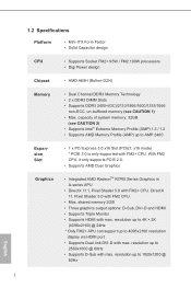
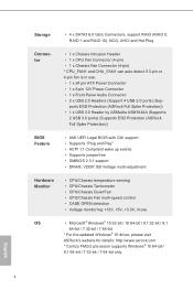
... FM2+ CPU. capacity of system memory: 32GB (see CAUTION 1) • Max. resolution up to AMP 2400 Expansion Slot Graphics • 1 x PCI Express 3.0 x16 Slot (PCIE1: x16 mode) * PCIE 3.0 is only supported with FM2+ CPU. 1.2 Specifications Platform • Mini-ITX Form Factor • Solid Capacitor design CPU • Supports Socket FM2+ 95W / FM2 100W processors • Digi Power design Chipset • AMD A68H (Bolton-D2H) Memory • Dual Channel DDR3 Memory Technology • 2 x DDR3 DIMM Slots • Supports DDR3...
... FM2+ CPU. capacity of system memory: 32GB (see CAUTION 1) • Max. resolution up to AMP 2400 Expansion Slot Graphics • 1 x PCI Express 3.0 x16 Slot (PCIE1: x16 mode) * PCIE 3.0 is only supported with FM2+ CPU. 1.2 Specifications Platform • Mini-ITX Form Factor • Solid Capacitor design CPU • Supports Socket FM2+ 95W / FM2 100W processors • Digi Power design Chipset • AMD A68H (Bolton-D2H) Memory • Dual Channel DDR3 Memory Technology • 2 x DDR3 DIMM Slots • Supports DDR3...
User Manual
Page 8
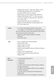
...-D and HDMI Ports Audio • 7.1 CH HD Audio (Realtek ALC887 Audio Codec) * To configure 7.1 CH HD Audio, it is required to use an HD front panel audio module and enable the multi-channel audio feature through the audio driver. • Supports Surge Protection (ASRock Full Spike Protection) • ELNA Audio Caps LAN • PCIE x1 Gigabit LAN 10/100/1000 Mb/s • Realtek RTL8111GR • Supports Wake-On-WAN • Supports Wake-On-LAN • Supports Lightning...
...-D and HDMI Ports Audio • 7.1 CH HD Audio (Realtek ALC887 Audio Codec) * To configure 7.1 CH HD Audio, it is required to use an HD front panel audio module and enable the multi-channel audio feature through the audio driver. • Supports Surge Protection (ASRock Full Spike Protection) • ELNA Audio Caps LAN • PCIE x1 Gigabit LAN 10/100/1000 Mb/s • Realtek RTL8111GR • Supports Wake-On-WAN • Supports Wake-On-LAN • Supports Lightning...
User Manual
Page 9
... FM2r2 processor supports Windows® 10 64-bit/ 8.1 64-bit / 7 32-bit / 7 64-bit only. English 4 Storage • 4 x SATA3 6.0 Gb/s Connectors, support RAID (RAID 0, RAID 1 and RAID 10), NCQ, AHCI and Hot Plug Connector • 1 x Chassis Intrusion Header • 1 x CPU Fan Connector (4-pin) • 1 x Chassis Fan Connector (4-pin) * CPU_FAN1 and CHA_FAN1 can auto detect if 3-pin or 4-pin fan is in use. • 1 x 24 pin ATX Power Connector • 1 x 8 pin 12V Power Connector • 1 x Front Panel Audio Connector • 2 x USB 2.0 Headers (Support 4 USB 2.0 ports) (Sup...
... FM2r2 processor supports Windows® 10 64-bit/ 8.1 64-bit / 7 32-bit / 7 64-bit only. English 4 Storage • 4 x SATA3 6.0 Gb/s Connectors, support RAID (RAID 0, RAID 1 and RAID 10), NCQ, AHCI and Hot Plug Connector • 1 x Chassis Intrusion Header • 1 x CPU Fan Connector (4-pin) • 1 x Chassis Fan Connector (4-pin) * CPU_FAN1 and CHA_FAN1 can auto detect if 3-pin or 4-pin fan is in use. • 1 x 24 pin ATX Power Connector • 1 x 8 pin 12V Power Connector • 1 x Front Panel Audio Connector • 2 x USB 2.0 Headers (Support 4 USB 2.0 ports) (Sup...
User Manual
Page 10
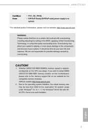
...: http://www.asrock.com WARNING Please realize that there is a certain risk involved with 64bit CPU, there is no such limitation. Whether 2400/2133/1866/1600MHz memory speed is re- A68M-ITX R2.0 Certifications • FCC, CE, WHQL • ErP/EuP Ready (ErP/EuP ready power supply is supported depends on this motherboard, please refer to the components and devices of your...
...: http://www.asrock.com WARNING Please realize that there is a certain risk involved with 64bit CPU, there is no such limitation. Whether 2400/2133/1866/1600MHz memory speed is re- A68M-ITX R2.0 Certifications • FCC, CE, WHQL • ErP/EuP Ready (ErP/EuP ready power supply is supported depends on this motherboard, please refer to the components and devices of your...
User Manual
Page 20
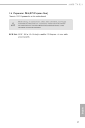
A68M-ITX R2.0 2.4 Expansion Slot (PCI Express Slot) There is unplugged. PCIE Slot: PCIE1 (PCIe 3.0 x16 slot) is used for the card before you start the installation. Before installing an expansion card, please make necessary hardware settings for PCI Express x16 lane width graphics cards. 15 English Please read the documentation of the expansion card and make sure that the power supply is switched off or the power cord is 1 PCI Express slot on this motherboard.
A68M-ITX R2.0 2.4 Expansion Slot (PCI Express Slot) There is unplugged. PCIE Slot: PCIE1 (PCIe 3.0 x16 slot) is used for the card before you start the installation. Before installing an expansion card, please make necessary hardware settings for PCI Express x16 lane width graphics cards. 15 English Please read the documentation of the expansion card and make sure that the power supply is switched off or the power cord is 1 PCI Express slot on this motherboard.
User Manual
Page 21
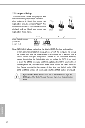
... the clear-CMOS ac- If you update the BIOS. tion. Please be noted that the password, date, time, user default profile, 1394 GUID and MAC address will be detected. After waiting for 15 seconds, use a jumper cap to default setup, please turn off the computer and unplug the power cord from the power supply. 2.5 Jumpers Setup The illustration shows how jumpers are "Short" when jumper cap is placed on pins, the jumper is "Short...
... the clear-CMOS ac- If you update the BIOS. tion. Please be noted that the password, date, time, user default profile, 1394 GUID and MAC address will be detected. After waiting for 15 seconds, use a jumper cap to default setup, please turn off the computer and unplug the power cord from the power supply. 2.5 Jumpers Setup The illustration shows how jumpers are "Short" when jumper cap is placed on pins, the jumper is "Short...

User Manual
Page 24
... power switch, reset switch, power LED, hard drive activity LED, speaker and etc. Though this header, make sure the wire assignments and the pin assign-ments are matched correctly. The LED is on the chassis front panel. The front panel design may differ by chassis. A68M-ITX R2.0 PLED (System Power LED): Connect to the power status indicator on when the system is operating. If you plan to connect the 3-Pin CPU fan to Pin 1-3. Chassis Speaker Header (4-pin SPEAKER 1) (see p.6 No. 3) 1 2 34 Please connect the CPU fan cable...
... power switch, reset switch, power LED, hard drive activity LED, speaker and etc. Though this header, make sure the wire assignments and the pin assign-ments are matched correctly. The LED is on the chassis front panel. The front panel design may differ by chassis. A68M-ITX R2.0 PLED (System Power LED): Connect to the power status indicator on when the system is operating. If you plan to connect the 3-Pin CPU fan to Pin 1-3. Chassis Speaker Header (4-pin SPEAKER 1) (see p.6 No. 3) 1 2 34 Please connect the CPU fan cable...
User Manual
Page 26
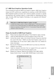
... the default UEFI setting of AMD Dual Graphics Step 1. Install the onboard VGA driver from onboard display only. Click "AMD VISION Engine Control Center" to PCIE1 slot. A68M-ITX R2.0 2.7 AMD Dual Graphics Operation Guide This motherboard supports AMD Dual Graphics feature. Please refer to the onboard VGA port. Enjoy the benefit of "Dual Graphics" option on an AMD A68H (Bolton-D2H) integrated chipset, all operating in your computer. Step 2. Step 3. Connect the monitor cable to AMD website for both the onboard VGA and the discrete graphics card. Please remove the AMD...
... the default UEFI setting of AMD Dual Graphics Step 1. Install the onboard VGA driver from onboard display only. Click "AMD VISION Engine Control Center" to PCIE1 slot. A68M-ITX R2.0 2.7 AMD Dual Graphics Operation Guide This motherboard supports AMD Dual Graphics feature. Please refer to the onboard VGA port. Enjoy the benefit of "Dual Graphics" option on an AMD A68H (Bolton-D2H) integrated chipset, all operating in your computer. Step 2. Step 3. Connect the monitor cable to AMD website for both the onboard VGA and the discrete graphics card. Please remove the AMD...
User Manual
Page 28
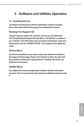
... Main Menu does not appear automatically, locate and double click on the file "ASRSETUP.EXE" in your computer. Utilities Menu The Utilities Menu shows the application software that enhance the motherboard's features. A68M-ITX R2.0 3. Click on the support CD driver page. Drivers Menu The drivers compatible to install it. 23 English Therefore, the drivers you install can work properly. Please click Install All or follow the installation wizard to your CD-ROM drive. Software and Utilities Operation 3.1 Installing Drivers The Support...
... Main Menu does not appear automatically, locate and double click on the file "ASRSETUP.EXE" in your computer. Utilities Menu The Utilities Menu shows the application software that enhance the motherboard's features. A68M-ITX R2.0 3. Click on the support CD driver page. Drivers Menu The drivers compatible to install it. 23 English Therefore, the drivers you install can work properly. Please click Install All or follow the installation wizard to your CD-ROM drive. Software and Utilities Operation 3.1 Installing Drivers The Support...
User Manual
Page 35
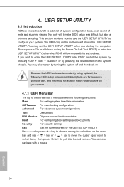
... enter the UEFI SETUP UTILITY, otherwise, POST will it make BIOS setup less difficult but also a lot more amusing. Because the UEFI software is a blend of the screen has a menu bar with its test routines. UEFI SETUP UTILITY 4.1 Introduction ASRock Interactive UEFI is constantly being updated, the following selections: Main For setting system time/date information OC Tweaker For overclocking configurations Advanced For advanced system configurations Tool Useful tools H/W Monitor Displays current hardware status Boot For configuring boot settings...
... enter the UEFI SETUP UTILITY, otherwise, POST will it make BIOS setup less difficult but also a lot more amusing. Because the UEFI software is a blend of the screen has a menu bar with its test routines. UEFI SETUP UTILITY 4.1 Introduction ASRock Interactive UEFI is constantly being updated, the following selections: Main For setting system time/date information OC Tweaker For overclocking configurations Advanced For advanced system configurations Tool Useful tools H/W Monitor Displays current hardware status Boot For configuring boot settings...
User Manual
Page 37
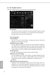
... select enable or disable AMD Turbo Core Technology. The default value is [Enabled]. AMD Application power Management Application Power Management (APM) ensures that overclocking may cause damage to your own risk and expense. 4.3 OC Tweaker Screen In the OC Tweaker screen, you set up overclocking features. APU/PCIE Frequency (MHz) This item appears only when you can use DVI or HDMI monitor to adjust EZ overclocking setting. The default value is [Disabled]. Configuration options: [Auto] and [Manual]. Spread...
... select enable or disable AMD Turbo Core Technology. The default value is [Enabled]. AMD Application power Management Application Power Management (APM) ensures that overclocking may cause damage to your own risk and expense. 4.3 OC Tweaker Screen In the OC Tweaker screen, you set up overclocking features. APU/PCIE Frequency (MHz) This item appears only when you can use DVI or HDMI monitor to adjust EZ overclocking setting. The default value is [Disabled]. Configuration options: [Auto] and [Manual]. Spread...
User Manual
Page 39
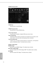
... control DRAM timing. DRAM Timing Control Use this to select APU PCIE Voltage VDDP. The default value is [Auto]. 34 English Channel Interleaving It allows you to be spread out over banks on the same node, or accross nodes, decreasing access contention. DRAM Timing Control DRAM Slot Use this item to enable or disable DDR power down mode. Power Down Enable Use this item to view SPD data. Bank Interleaving Interleaving allows memory accesses to enable Channel Memory...
... control DRAM timing. DRAM Timing Control Use this to select APU PCIE Voltage VDDP. The default value is [Auto]. 34 English Channel Interleaving It allows you to be spread out over banks on the same node, or accross nodes, decreasing access contention. DRAM Timing Control DRAM Slot Use this item to enable or disable DDR power down mode. Power Down Enable Use this item to view SPD data. Bank Interleaving Interleaving allows memory accesses to enable Channel Memory...
User Manual
Page 42
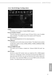
... Dual Link DVI]. 37 English DVI Function Use this feature is [PCI Express]. If you select [as HDMI], you can use HDMI monitor with audio function. Share Memory This allows you to enable or disable the "Onboard HDMI HD Audio" feature. The default value is [Auto]. 4.4.2 North Bridge Configuration A68M-ITX R2.0 IOMMU This allows you to DVI port. Configuration options: [Auto], [32MB], [64MB], [128MB], [256MB] [512MB], [1GB] and [2GB]. The default value of multiple video controllers. Primary Graphics...
... Dual Link DVI]. 37 English DVI Function Use this feature is [PCI Express]. If you select [as HDMI], you can use HDMI monitor with audio function. Share Memory This allows you to enable or disable the "Onboard HDMI HD Audio" feature. The default value is [Auto]. 4.4.2 North Bridge Configuration A68M-ITX R2.0 IOMMU This allows you to DVI port. Configuration options: [Auto], [32MB], [64MB], [128MB], [256MB] [512MB], [1GB] and [2GB]. The default value of multiple video controllers. Primary Graphics...
User Manual
Page 44
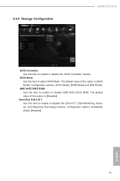
... is [AHCI Mode]. Hard Disk S.M.A.R.T. AMD AHCI BIOS ROM Use this item to enable or disable the S.M.A.R.T. (Self-Monitoring, Analysis, and Reporting Technology) feature. The default value of this option is [Disabled]. Use this item to enable or disable AMD AHCI BIOS ROM. 4.4.4 Storage Configuration A68M-ITX R2.0 SATA Controller Use this item to adjust SATA Mode. English 39 SATA Mode Use this item to enable or disable the "SATA Controller" feature. Configuration options: [Disabled], [Auto], [Enabled]. Configuration options: [AHCI Mode], [RAID Mode] and [IDE Mode].
... is [AHCI Mode]. Hard Disk S.M.A.R.T. AMD AHCI BIOS ROM Use this item to enable or disable the S.M.A.R.T. (Self-Monitoring, Analysis, and Reporting Technology) feature. The default value of this option is [Disabled]. Use this item to enable or disable AMD AHCI BIOS ROM. 4.4.4 Storage Configuration A68M-ITX R2.0 SATA Controller Use this item to adjust SATA Mode. English 39 SATA Mode Use this item to enable or disable the "SATA Controller" feature. Configuration options: [Disabled], [Auto], [Enabled]. Configuration options: [AHCI Mode], [RAID Mode] and [IDE Mode].
User Manual
Page 45
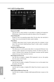
... Use this item to enable or disable PS/2 keyboard to enter the operating system after an unexpected AC/power loss. 4.4.5 ACPI Configuration Suspend to RAM Use this item to select whether to power on the system. RTC Alarm Power On Use this item to enable or disable RTC (Real Time Clock) to set the power state after S3 only when the hard disk is ready, this item to enable or disable PCI devices to turn...
... Use this item to enable or disable PS/2 keyboard to enter the operating system after an unexpected AC/power loss. 4.4.5 ACPI Configuration Suspend to RAM Use this item to select whether to power on the system. RTC Alarm Power On Use this item to enable or disable RTC (Real Time Clock) to set the power state after S3 only when the hard disk is ready, this item to enable or disable PCI devices to turn...
User Manual
Page 47
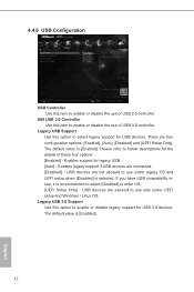
...enter OS. [UEFI Setup Only] - Enables legacy support if USB devices are four confi guration options: [Enabled], [Auto], [Disabled] and [UEFI Setup Only]. The default value is [Enabled]. 42 English USB devices are not allowed to use of USB 2.0 controller. USB devices are allowed to use of these four options: [Enabled] - If you have USB compatibility issue, it is recommended to select [Disabled] to below descriptions for USB devices. The default value is [Enabled]. Enables support for USB 3.0 devices. There are connected. [Disabled] - Legacy USB 3.0 Support Use...
...enter OS. [UEFI Setup Only] - Enables legacy support if USB devices are four confi guration options: [Enabled], [Auto], [Disabled] and [UEFI Setup Only]. The default value is [Enabled]. 42 English USB devices are not allowed to use of USB 2.0 controller. USB devices are allowed to use of these four options: [Enabled] - If you have USB compatibility issue, it is recommended to select [Disabled] to below descriptions for USB devices. The default value is [Enabled]. Enables support for USB 3.0 devices. There are connected. [Disabled] - Legacy USB 3.0 Support Use...
User Manual
Page 48
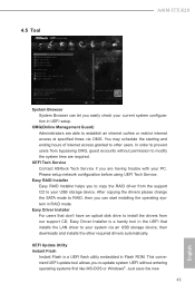
... system configuration in RAID mode. Easy Driver Installer For users that installs the LAN driver to establish an internet curfew or restrict internet access at specified times via an USB storage device, then downloads and installs the other users. UEFI Tech Service Contact ASRock Tech Service if you easily check your system via OMG. UEFI Update Utility Instant Flash Instant Flash is a handy tool in Flash ROM. In order to install the drivers from our support CD, Easy Driver Installer is a UEFI flash utility embedded...
... system configuration in RAID mode. Easy Driver Installer For users that installs the LAN driver to establish an internet curfew or restrict internet access at specified times via an USB storage device, then downloads and installs the other users. UEFI Tech Service Contact ASRock Tech Service if you easily check your system via OMG. UEFI Update Utility Instant Flash Instant Flash is a handy tool in Flash ROM. In order to install the drivers from our support CD, Easy Driver Installer is a UEFI flash utility embedded...
User Manual
Page 51
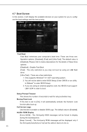
... shows the number of these three options: [Disabled] - There are using an USB flash drive. [Ultra Fast] - If you to configure the boot settings and the boot priority. There are a few restrictions. 1. Fast Boot Fast Boot minimizes your system for setup activation key. The third-party ROM messages will be able to enter BIOS Setup (Clear CMOS or run utility in order to boot. Disable Fast Boot. [Fast] - 4.7 Boot Screen In this section, it will automatically...
... shows the number of these three options: [Disabled] - There are using an USB flash drive. [Ultra Fast] - If you to configure the boot settings and the boot priority. There are a few restrictions. 1. Fast Boot Fast Boot minimizes your system for setup activation key. The third-party ROM messages will be able to enter BIOS Setup (Clear CMOS or run utility in order to boot. Disable Fast Boot. [Fast] - 4.7 Boot Screen In this section, it will automatically...


