User Manual
Page 8
Hardware - ErP/EuP Ready (ErP/EuP ready power supply is required) (see CAUTION 13) * For detailed product information, please visit our website: http://www.asrock.com WARNING Please realize that there is a certain risk involved with overclocking, including adjusting the ... overclocking tools. We are not responsible for possible damage caused by overclocking. 8 Chassis Temperature Sensing - CPU/Chassis Fan Multi-Speed Control - CPU/Chassis/Power Fan Tachometer - Voltage Monitoring: +12V, +5V, +3.3V, Vcore OS - It should be done at your system. Microsoft® Windows® ...
Hardware - ErP/EuP Ready (ErP/EuP ready power supply is required) (see CAUTION 13) * For detailed product information, please visit our website: http://www.asrock.com WARNING Please realize that there is a certain risk involved with overclocking, including adjusting the ... overclocking tools. We are not responsible for possible damage caused by overclocking. 8 Chassis Temperature Sensing - CPU/Chassis Fan Multi-Speed Control - CPU/Chassis/Power Fan Tachometer - Voltage Monitoring: +12V, +5V, +3.3V, Vcore OS - It should be done at your system. Microsoft® Windows® ...
User Manual
Page 10
... dissipation, remember to de ne the power consumption for the completed system. For EuP ready power supply selection, we recommend you to RAM (S3), hibernation mode (S4) or power off mode condition. ASRock APP Charger allows you checking with the power supply manufacturer for you desire a faster, less...and your computer and up to Intel's suggestion, the EuP ready power supply must meet EuP standard, an EuP ready motherboard and an EuP ready power supply are exclusively equipped with friends on-the-go. ASRock APP Charger. To use SmartView feature, please make sure your OS...
... dissipation, remember to de ne the power consumption for the completed system. For EuP ready power supply selection, we recommend you to RAM (S3), hibernation mode (S4) or power off mode condition. ASRock APP Charger allows you checking with the power supply manufacturer for you desire a faster, less...and your computer and up to Intel's suggestion, the EuP ready power supply must meet EuP standard, an EuP ready motherboard and an EuP ready power supply are exclusively equipped with friends on-the-go. ASRock APP Charger. To use SmartView feature, please make sure your OS...

User Manual
Page 13
Unplug the power cord from the power supply. Installation This is detached from the wall socket before you install motherboard components or change any component, ensure that the power is switched off or the power cord is a Micro ATX form factor (8.9-in x 8.5-in the bag that the motherboard ts into the screw holes to secure the...
Unplug the power cord from the power supply. Installation This is detached from the wall socket before you install motherboard components or change any component, ensure that the power is switched off or the power cord is a Micro ATX form factor (8.9-in x 8.5-in the bag that the motherboard ts into the screw holes to secure the...

User Manual
Page 15
.... 1. notch break notch break The DIMM only ts in one memory module or two non-identical memory modules, it will cause permanent damage to disconnect power supply before adding or removing DIMMs or the system components.
.... 1. notch break notch break The DIMM only ts in one memory module or two non-identical memory modules, it will cause permanent damage to disconnect power supply before adding or removing DIMMs or the system components.

User Manual
Page 16
... Express Slots) There are 1 PCI slot and 2 PCI Express slots on the slot. Step 4. Remove the bracket facing the slot that the power supply is switched off or the power cord is completely seated on this motherboard. Step 3. Fasten the card to use . Align the card connector with screws. Please read the documentation...
... Express Slots) There are 1 PCI slot and 2 PCI Express slots on the slot. Step 4. Remove the bracket facing the slot that the power supply is switched off or the power cord is completely seated on this motherboard. Step 3. Fasten the card to use . Align the card connector with screws. Please read the documentation...

User Manual
Page 23
... shut it down before you do not clear the CMOS right after you to default setup, please turn off the computer and unplug the power cord from the power supply. Please be noted that the password, date, time, user default pro le, 1394 GUID and MAC address will be cleared only if the...
... shut it down before you do not clear the CMOS right after you to default setup, please turn off the computer and unplug the power cord from the power supply. Please be noted that the password, date, time, user default pro le, 1394 GUID and MAC address will be cleared only if the...
User Manual
Page 26
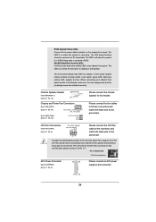
...etc. CPU Fan Connectors (4-pin CPU_FAN1) (see p.11 No. 6) 12 24 Please connect an ATX power supply to this connector. 1 13 26 PLED (System Power LED): Connect to the power status indicator on the chassis front panel. The front panel design may differ by chassis. Though this header...sure the wire assignments and the pin assign-ments are matched correctly. Chassis Speaker Header (4-pin SPEAKER 1) (see p.11 No. 13) Chassis and Power Fan Connectors (4-pin CHA_FAN1) (see p.11 No. 19) FAN_SPEED_CONTROL GND +12V CHA_FAN_SPEED (3-pin PWR_FAN1) (see p.11 No. 30) PWR_FAN_SPEED +12V...
...etc. CPU Fan Connectors (4-pin CPU_FAN1) (see p.11 No. 6) 12 24 Please connect an ATX power supply to this connector. 1 13 26 PLED (System Power LED): Connect to the power status indicator on the chassis front panel. The front panel design may differ by chassis. Though this header...sure the wire assignments and the pin assign-ments are matched correctly. Chassis Speaker Header (4-pin SPEAKER 1) (see p.11 No. 13) Chassis and Power Fan Connectors (4-pin CHA_FAN1) (see p.11 No. 19) FAN_SPEED_CONTROL GND +12V CHA_FAN_SPEED (3-pin PWR_FAN1) (see p.11 No. 30) PWR_FAN_SPEED +12V...

User Manual
Page 27
... can still work if you adopt a traditional 20-pin ATX power supply. To use the 20-pin ATX power supply, please plug your power supply along with Pin 1 and Pin 5. 4-Pin ATX 12V Power Supply Installation 8 4 Serial port Header (9-pin COM1) (see p.11 No. 1) 5 1 8 4 Please connect an ATX 12V power supply to this connector. Though this motherboard provides 8-pin ATX...
... can still work if you adopt a traditional 20-pin ATX power supply. To use the 20-pin ATX power supply, please plug your power supply along with Pin 1 and Pin 5. 4-Pin ATX 12V Power Supply Installation 8 4 Serial port Header (9-pin COM1) (see p.11 No. 1) 5 1 8 4 Please connect an ATX 12V power supply to this connector. Though this motherboard provides 8-pin ATX...
User Manual
Page 29
... SATA 15-pin power connector and IDE 1x4-pin conventional power connector interfaces, the IDE 1x4-pin conventional power connector interface is de nitely not able to power supply Caution 1. SATA power cable with SATA 15-pin power connector interface A. SATA... data cable (Red) B. Make sure to use the SATA power cable & data cable, which cannot support Hot Plug function, will cause the HDD damage and data loss. Below operation procedure is available on our website: www.asrock...
... SATA 15-pin power connector and IDE 1x4-pin conventional power connector interfaces, the IDE 1x4-pin conventional power connector interface is de nitely not able to power supply Caution 1. SATA power cable with SATA 15-pin power connector interface A. SATA... data cable (Red) B. Make sure to use the SATA power cable & data cable, which cannot support Hot Plug function, will cause the HDD damage and data loss. Below operation procedure is available on our website: www.asrock...

User Manual
Page 30
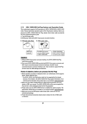
... process the Hot Unplug, improper procedure will cause the SATA / SATAII HDD damage and data loss. SATA power cable 1x4-pin power connector (White) Step 3 Connect SATA 15-pin power cable connector (Black) end to the power supply 1x4-pin cable. How to Hot Plug a SATA / SATAII HDD: Points of attention, before you process the...
... process the Hot Unplug, improper procedure will cause the SATA / SATAII HDD damage and data loss. SATA power cable 1x4-pin power connector (White) Step 3 Connect SATA 15-pin power cable connector (Black) end to the power supply 1x4-pin cable. How to Hot Plug a SATA / SATAII HDD: Points of attention, before you process the...

User Manual
Page 41
... function, please set this function may reduce CPU voltage and memory frequency, and lead to system stability or compatibility issue with some memory modules or power supplies. SVM When this option is [Auto]. 41 The default value is set this item to enable or disable AMD's Cool 'n' QuietTM technology. Please note that...
... function, please set this function may reduce CPU voltage and memory frequency, and lead to system stability or compatibility issue with some memory modules or power supplies. SVM When this option is [Auto]. 41 The default value is set this item to enable or disable AMD's Cool 'n' QuietTM technology. Please note that...
Quick Installation Guide
Page 7
.../EuP ready power supply is required) (see CAUTION 13) * For detailed product information, please visit our website: http://www.asrock.com WARNING Please realize that there is a certain risk involved with overclocking, including adjusting the setting in the BIOS, applying Untied Overclocking Technology, or using the third-party overclocking tools. English 7 ASRock A55M-HVS Motherboard CPU... your system. Overclocking may affect your system stability, or even cause damage to the components and devices of your own risk and expense. CPU/Chassis/Power Fan Tachometer -
.../EuP ready power supply is required) (see CAUTION 13) * For detailed product information, please visit our website: http://www.asrock.com WARNING Please realize that there is a certain risk involved with overclocking, including adjusting the setting in the BIOS, applying Untied Overclocking Technology, or using the third-party overclocking tools. English 7 ASRock A55M-HVS Motherboard CPU... your system. Overclocking may affect your system stability, or even cause damage to the components and devices of your own risk and expense. CPU/Chassis/Power Fan Tachometer -

Quick Installation Guide
Page 9
If you desire a faster, less restricted way of charging your Apple devices, such as iPhone/iPod/iPad Touch, ASRock has prepared a wonderful solution for you checking with the power supply manufacturer for a more details. 9 ASRock A55M-HVS Motherboard English ASRock APP Charger allows you are required. Real-Time Analysis of Your Data: With the status window, you can...
If you desire a faster, less restricted way of charging your Apple devices, such as iPhone/iPod/iPad Touch, ASRock has prepared a wonderful solution for you checking with the power supply manufacturer for a more details. 9 ASRock A55M-HVS Motherboard English ASRock APP Charger allows you are required. Real-Time Analysis of Your Data: With the status window, you can...
Quick Installation Guide
Page 10
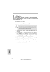
... by the edges and do so may damage the motherboard. 10 ASRock A55M-HVS Motherboard English Installation This is detached from the wall socket before touching any component, ensure that the power is switched off or the power cord is a Micro ATX form factor (8.9-in x 8.5-in the...your chassis to use a grounded wrist strap or touch a safety grounded object before you handle components. 3. Unplug the power cord from the power supply. Whenever you install the motherboard, study the configuration of the following precautions before you install motherboard components or ...
... by the edges and do so may damage the motherboard. 10 ASRock A55M-HVS Motherboard English Installation This is detached from the wall socket before touching any component, ensure that the power is switched off or the power cord is a Micro ATX form factor (8.9-in x 8.5-in the...your chassis to use a grounded wrist strap or touch a safety grounded object before you handle components. 3. Unplug the power cord from the power supply. Whenever you install the motherboard, study the configuration of the following precautions before you install motherboard components or ...

Quick Installation Guide
Page 12
... install two identical (the same brand, speed, size and chiptype) memory modules in place and the DIMM is properly seated. 12 ASRock A55M-HVS Motherboard English It is unable to disconnect power supply before adding or removing DIMMs or the system components. It will operate at single channel mode. 1. Firmly insert the DIMM into DDR3...
... install two identical (the same brand, speed, size and chiptype) memory modules in place and the DIMM is properly seated. 12 ASRock A55M-HVS Motherboard English It is unable to disconnect power supply before adding or removing DIMMs or the system components. It will operate at single channel mode. 1. Firmly insert the DIMM into DDR3...
Quick Installation Guide
Page 13
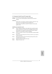
...ASRock A55M-HVS Motherboard English PCIE2 (PCIE x16 slot; Before installing the expansion card, please make necessary hardware settings for PCI Express x16 lane width graphics cards. Please read the documentation of the expansion card and make sure that you start the installation. Remove the bracket facing the slot that the power supply... is switched off or the power cord is completely seated on this motherboard. Align the card connector with x1 lane width cards, such...
...ASRock A55M-HVS Motherboard English PCIE2 (PCIE x16 slot; Before installing the expansion card, please make necessary hardware settings for PCI Express x16 lane width graphics cards. Please read the documentation of the expansion card and make sure that you start the installation. Remove the bracket facing the slot that the power supply... is switched off or the power cord is completely seated on this motherboard. Align the card connector with x1 lane width cards, such...

Quick Installation Guide
Page 20
... pin2 and pin3 on CLRCMOS1 for 15 seconds, use a jumper cap to default setup, please turn off the computer and unplug the power cord from the power supply. The illustration shows a 3-pin jumper whose pin1 and pin2 are setup. After waiting for 5 seconds. However, please do the clear...date, time, user default profile, 1394 GUID and MAC address will be cleared only if the CMOS battery is "Open". English 20 ASRock A55M-HVS Motherboard Jumper Clear CMOS Jumper (CLRCMOS1) (see p.2, No. 18) Setting Default Clear CMOS Description Note: CLRCMOS1 allows you to clear the CMOS...
... pin2 and pin3 on CLRCMOS1 for 15 seconds, use a jumper cap to default setup, please turn off the computer and unplug the power cord from the power supply. The illustration shows a 3-pin jumper whose pin1 and pin2 are setup. After waiting for 5 seconds. However, please do the clear...date, time, user default profile, 1394 GUID and MAC address will be cleared only if the CMOS battery is "Open". English 20 ASRock A55M-HVS Motherboard Jumper Clear CMOS Jumper (CLRCMOS1) (see p.2, No. 18) Setting Default Clear CMOS Description Note: CLRCMOS1 allows you to clear the CMOS...
Quick Installation Guide
Page 23
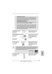
... to connect the 3-Pin CPU fan to the CPU fan connector on when the system is in S3/S4 sleep state or powered off (S5). English 1 13 23 ASRock A55M-HVS Motherboard CPU Fan Connectors (4-pin CPU_FAN1) (see p.2 No. 4) FAN_SPEED_CONTROL CPU_FAN_SPEED +12V GND 1 2 3 4 Please connect ...Speaker Header (4-pin SPEAKER 1) (see p.2 No. 13) Chassis and Power Fan Connectors (4-pin CHA_FAN1) (see p.2 No. 19) FAN_SPEED_CONTROL GND +12V CHA_FAN_SPEED (3-pin PWR_FAN1) (see p.2 No. 6) 12 24 Please connect an ATX power supply to the hard drive activity LED on when the hard drive is ...
... to connect the 3-Pin CPU fan to the CPU fan connector on when the system is in S3/S4 sleep state or powered off (S5). English 1 13 23 ASRock A55M-HVS Motherboard CPU Fan Connectors (4-pin CPU_FAN1) (see p.2 No. 4) FAN_SPEED_CONTROL CPU_FAN_SPEED +12V GND 1 2 3 4 Please connect ...Speaker Header (4-pin SPEAKER 1) (see p.2 No. 13) Chassis and Power Fan Connectors (4-pin CHA_FAN1) (see p.2 No. 19) FAN_SPEED_CONTROL GND +12V CHA_FAN_SPEED (3-pin PWR_FAN1) (see p.2 No. 6) 12 24 Please connect an ATX power supply to the hard drive activity LED on when the hard drive is ...

Quick Installation Guide
Page 24
English 24 ASRock A55M-HVS Motherboard To use the 20-pin ATX power supply, please plug your power supply along with Pin 1 and Pin 5. 4-Pin ATX 12V Power Supply Installation 8 4 Serial port Header (9-pin COM1) (see p.2 No. 1) 5 1 8 4 Please connect an ATX 12V power supply to this connector. To use the 5 1 4-pin ATX power supply, please plug your power supply along with Pin 1 and Pin 13. 20...
English 24 ASRock A55M-HVS Motherboard To use the 20-pin ATX power supply, please plug your power supply along with Pin 1 and Pin 5. 4-Pin ATX 12V Power Supply Installation 8 4 Serial port Header (9-pin COM1) (see p.2 No. 1) 5 1 8 4 Please connect an ATX 12V power supply to this connector. To use the 5 1 4-pin ATX power supply, please plug your power supply along with Pin 1 and Pin 13. 20...

