
User Manual
Page 4
... Specifications 2 1.3 Motherboard Layout 6 1.4 I/O Panel 8 Chapter 2 Installation 10 2.1 Installing the CPU 11 2.2 Installing the CPU Fan and Heatsink 13 2.3 Installing Memory Modules (DIMM) 21 2.4 Expansion Slots (PCI Express Slots) 24 2.5 Jumpers Setup 25 2.6 Onboard Headers and Connectors 26 2.7 M.2_SSD (NGFF) Module Installation Guide (M2_1) 31 2.8 M.2_SSD (NGFF) Module Installation Guide (M2_2) 34 Chapter 3 Software and Utilities Operation 37 3.1 Installing Drivers 37 3.2 ASRock Motherboard Utility (Phantom Gaming Tuning) 38 3.2.1 Installing ASRock Motherboard...
... Specifications 2 1.3 Motherboard Layout 6 1.4 I/O Panel 8 Chapter 2 Installation 10 2.1 Installing the CPU 11 2.2 Installing the CPU Fan and Heatsink 13 2.3 Installing Memory Modules (DIMM) 21 2.4 Expansion Slots (PCI Express Slots) 24 2.5 Jumpers Setup 25 2.6 Onboard Headers and Connectors 26 2.7 M.2_SSD (NGFF) Module Installation Guide (M2_1) 31 2.8 M.2_SSD (NGFF) Module Installation Guide (M2_2) 34 Chapter 3 Software and Utilities Operation 37 3.1 Installing Drivers 37 3.2 ASRock Motherboard Utility (Phantom Gaming Tuning) 38 3.2.1 Installing ASRock Motherboard...
User Manual
Page 6
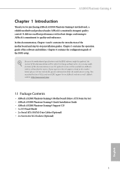
... quality control. In this documentation occur, the updated version will be available on ASRock's website as well. You may find the latest VGA cards and CPU support list on ASRock's website without notice. ASRock website http://www.asrock.com. 1.1 Package Contents • ASRock A520M Phantom Gaming 4 Motherboard (Micro ATX Form Factor) • ASRock A520M Phantom Gaming 4 Quick Installation Guide • ASRock A520M Phantom Gaming 4 Support CD • 1 x I/O Panel Shield • 2 x Serial ATA (SATA) Data Cables (Optional) • 2 x Screws for specific information about the model...
... quality control. In this documentation occur, the updated version will be available on ASRock's website as well. You may find the latest VGA cards and CPU support list on ASRock's website without notice. ASRock website http://www.asrock.com. 1.1 Package Contents • ASRock A520M Phantom Gaming 4 Motherboard (Micro ATX Form Factor) • ASRock A520M Phantom Gaming 4 Quick Installation Guide • ASRock A520M Phantom Gaming 4 Support CD • 1 x I/O Panel Shield • 2 x Serial ATA (SATA) Data Cables (Optional) • 2 x Screws for specific information about the model...

User Manual
Page 7
...: x2 mode)* * Supports NVMe SSD as boot disks • 1 x PCI Express 3.0 x1 Slot 2 1.2 Specifications Platform CPU • Micro ATX Form Factor • Solid Capacitor design • 2oz Copper PCB • Supports 3rd Gen AMD AM4 Ryzen™ / future AMD Ryzen™ Processors (3000 and 4000 Series Processors)* * Not compatible with AMD Ryzen™ 5 3400G and Ryzen™ 3 3200G. • Digi Power design • 8 Power Phase design Chipset • AMD A520 Memory • Dual Channel DDR4 Memory Technology...
...: x2 mode)* * Supports NVMe SSD as boot disks • 1 x PCI Express 3.0 x1 Slot 2 1.2 Specifications Platform CPU • Micro ATX Form Factor • Solid Capacitor design • 2oz Copper PCB • Supports 3rd Gen AMD AM4 Ryzen™ / future AMD Ryzen™ Processors (3000 and 4000 Series Processors)* * Not compatible with AMD Ryzen™ 5 3400G and Ryzen™ 3 3200G. • Digi Power design • 8 Power Phase design Chipset • AMD A520 Memory • Dual Channel DDR4 Memory Technology...

User Manual
Page 8
A520M Phantom Gaming 4 Graphics Audio LAN • Integrated AMD RadeonTM Vega Series Graphics in Ryzen Series APU* * Actual support may vary by independent display controllers • Supports HDMI 2.1 with max. resolution up to 4K x 2K (4096x2160) @ 60Hz • Supports DisplayPort 1.4 with HDMI 2.1 and DisplayPort 1.4 Ports • Supports Microsoft PlayReady® • 7.1 CH HD Audio (Realtek ALC 887/897 Audio Codec) • Supports Surge Protection • PCIE x1 Gigabit LAN 10/100/1000 Mb/s • Realtek RTL8111H...
A520M Phantom Gaming 4 Graphics Audio LAN • Integrated AMD RadeonTM Vega Series Graphics in Ryzen Series APU* * Actual support may vary by independent display controllers • Supports HDMI 2.1 with max. resolution up to 4K x 2K (4096x2160) @ 60Hz • Supports DisplayPort 1.4 with HDMI 2.1 and DisplayPort 1.4 Ports • Supports Microsoft PlayReady® • 7.1 CH HD Audio (Realtek ALC 887/897 Audio Codec) • Supports Surge Protection • PCIE x1 Gigabit LAN 10/100/1000 Mb/s • Realtek RTL8111H...

User Manual
Page 9
Rear Panel I/O • 1 x PS/2 Mouse/Keyboard Port • 1 x HDMI Port • 1 x DisplayPort 1.4 • 4 x USB 3.2 Gen1 Ports (Supports ESD Protection) • 2 x USB 2.0 Ports (Supports ESD Protection) • 1 x RJ-45 LAN Port with LED (ACT/LINK LED and SPEED LED) • HD Audio Jacks: Line in use. • 1 x 24 pin ATX Power Connector • 1 x 8 pin 12V Power Connector • 1 x Front Panel Audio Connector English 4 If either one of them is in use, the other one will be disabled. • 1 x Ultra M.2 Socket (M2_1), supports M Key type 2280 M.2 PCI Express module up...
Rear Panel I/O • 1 x PS/2 Mouse/Keyboard Port • 1 x HDMI Port • 1 x DisplayPort 1.4 • 4 x USB 3.2 Gen1 Ports (Supports ESD Protection) • 2 x USB 2.0 Ports (Supports ESD Protection) • 1 x RJ-45 LAN Port with LED (ACT/LINK LED and SPEED LED) • HD Audio Jacks: Line in use. • 1 x 24 pin ATX Power Connector • 1 x 8 pin 12V Power Connector • 1 x Front Panel Audio Connector English 4 If either one of them is in use, the other one will be disabled. • 1 x Ultra M.2 Socket (M2_1), supports M Key type 2280 M.2 PCI Express module up...
User Manual
Page 10
... devices of your own risk and expense. We are not responsible for possible damage caused by CPU tempera- A520M Phantom Gaming 4 BIOS Feature Hardware Monitor OS Certifications • 2 x USB 2.0 Headers (Support 4 USB 2.0 ports) (Supports ESD Protection) • 1 x USB 3.2 Gen1 Header (Supports 2 USB 3.2 Gen1 port) (Supports ESD Protection) • AMI UEFI Legal BIOS with overclocking, including adjusting the setting in the BIOS, applying Untied Overclocking Technology, or using third-party overclocking tools. adjustment • Temperature Sensing: CPU, Chassis/Water Pump Fans...
... devices of your own risk and expense. We are not responsible for possible damage caused by CPU tempera- A520M Phantom Gaming 4 BIOS Feature Hardware Monitor OS Certifications • 2 x USB 2.0 Headers (Support 4 USB 2.0 ports) (Supports ESD Protection) • 1 x USB 3.2 Gen1 Header (Supports 2 USB 3.2 Gen1 port) (Supports ESD Protection) • AMI UEFI Legal BIOS with overclocking, including adjusting the setting in the BIOS, applying Untied Overclocking Technology, or using third-party overclocking tools. adjustment • Temperature Sensing: CPU, Chassis/Water Pump Fans...

User Manual
Page 12
A520M Phantom Gaming 4 No. Description 1 8 pin 12V Power Connector (ATX12V1) 2 CPU Fan Connector (CPU_FAN1) 3 2 x 288-pin DDR4 DIMM Slots (DDR4_A1, DDR4_B1) 4 2 x 288-pin DDR4 DIMM Slots (DDR4_A2, DDR4_B2) 5 RGB LED Header (RGB_LED1) 6 Addressable LED Header (ADDR_LED1) 7 ATX Power Connector (ATXPWR1) 8 USB 3.2 Gen1 Header (F_USB3_1_2) 9 SATA3 Connector (SATA3_2) 10 SATA3 Connector (SATA3_1) 11 SATA3 Connector (SATA3_4)(Upper), SATA3 Connector (SATA3_3)(Lower) 12 System Panel Header (PANEL1) 13 Power LED and Speaker Header (SPK_PLED1) 14 Chassis/Water Pump Fan Connector (CHA_FAN3/WP) 15 USB ...
A520M Phantom Gaming 4 No. Description 1 8 pin 12V Power Connector (ATX12V1) 2 CPU Fan Connector (CPU_FAN1) 3 2 x 288-pin DDR4 DIMM Slots (DDR4_A1, DDR4_B1) 4 2 x 288-pin DDR4 DIMM Slots (DDR4_A2, DDR4_B2) 5 RGB LED Header (RGB_LED1) 6 Addressable LED Header (ADDR_LED1) 7 ATX Power Connector (ATXPWR1) 8 USB 3.2 Gen1 Header (F_USB3_1_2) 9 SATA3 Connector (SATA3_2) 10 SATA3 Connector (SATA3_1) 11 SATA3 Connector (SATA3_4)(Upper), SATA3 Connector (SATA3_3)(Lower) 12 System Panel Header (PANEL1) 13 Power LED and Speaker Header (SPK_PLED1) 14 Chassis/Water Pump Fan Connector (CHA_FAN3/WP) 15 USB ...
User Manual
Page 26
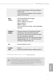
...-XMP Memory Frequency Support Ryzen Series CPUs (Matisse): UDIMM Memory Slot A1 A2 B1 B2 Frequency (Mhz) - SR - - 3200 - We suggest that you always need to install a DDR, DDR2 or DDR3 memory module into a DDR4 slot; SR 3200 - A520M Phantom Gaming 4 2.3 Installing Memory Modules (DIMM) This motherboard provides four 288-pin DDR4 (Double Data Rate 4) DIMM slots, and supports Dual Channel Memory Technology. 1. It is not allowed to install identical (the same brand, speed, size and chip-type...
...-XMP Memory Frequency Support Ryzen Series CPUs (Matisse): UDIMM Memory Slot A1 A2 B1 B2 Frequency (Mhz) - SR - - 3200 - We suggest that you always need to install a DDR, DDR2 or DDR3 memory module into a DDR4 slot; SR 3200 - A520M Phantom Gaming 4 2.3 Installing Memory Modules (DIMM) This motherboard provides four 288-pin DDR4 (Double Data Rate 4) DIMM slots, and supports Dual Channel Memory Technology. 1. It is not allowed to install identical (the same brand, speed, size and chip-type...

User Manual
Page 29
... power supply is switched off or the power cord is used for PCI Express x1 lane width cards. PCIe Slot Configurations Ryzen Series CPUs (Matisse) PCIE1 x16 PCIE2 x1 PCIE3 x2 Ryzen Series CPUs (Renoir) x16 x1 x2 For a better thermal environment, please connect a chassis fan to the motherboard's chassis fan connector (CHA_FAN1/WP, CHA_FAN2/WP or CHA_FAN3/WP) when using multiple graphics cards. PCIE2 (PCIe 3.0 x1 slot) is used for PCI Express x2 lane width graphics cards. PCIe slots: PCIE1 (PCIe 3.0 x16 slot...
... power supply is switched off or the power cord is used for PCI Express x1 lane width cards. PCIe Slot Configurations Ryzen Series CPUs (Matisse) PCIE1 x16 PCIE2 x1 PCIE3 x2 Ryzen Series CPUs (Renoir) x16 x1 x2 For a better thermal environment, please connect a chassis fan to the motherboard's chassis fan connector (CHA_FAN1/WP, CHA_FAN2/WP or CHA_FAN3/WP) when using multiple graphics cards. PCIE2 (PCIe 3.0 x1 slot) is used for PCI Express x2 lane width graphics cards. PCIe slots: PCIE1 (PCIe 3.0 x16 slot...
User Manual
Page 30
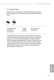
... system password, date, time, and system setup parameters. A520M Phantom Gaming 4 2.5 Jumpers Setup The illustration shows how jumpers are setup. Clear CMOS Jumper (CLRCMOS1) (see p.6, No. 19) 2-pin Jumper Short: Clear CMOS Open: Default CLRCMOS1 allows you to remove the jumper cap after clearing the CMOS. To clear and reset the system parameters to default setup, please turn off the computer and unplug the power cord, then use a jumper cap to clear the CMOS when you just finish updating the BIOS, you must boot up...
... system password, date, time, and system setup parameters. A520M Phantom Gaming 4 2.5 Jumpers Setup The illustration shows how jumpers are setup. Clear CMOS Jumper (CLRCMOS1) (see p.6, No. 19) 2-pin Jumper Short: Clear CMOS Open: Default CLRCMOS1 allows you to remove the jumper cap after clearing the CMOS. To clear and reset the system parameters to default setup, please turn off the computer and unplug the power cord, then use a jumper cap to clear the CMOS when you just finish updating the BIOS, you must boot up...

User Manual
Page 32
... SATA3_3 SATA3_2 These four SATA3 connectors support SATA data cables for internal storage devices with up to this motherboard. Please connect the chassis power LED and the chassis speaker to 6.0 Gb/s data transfer rate. * M2_2 and SATA3_3_4 share lanes. Serial ATA3 Connectors Vertical: (SATA3_1: see p.6, No. 10) (SATA3_2: see p.6, No. 9) Right Angle: (SATA3_3: see p.6, No. 11)(Lower) (SATA3_4: see p.6, No. 13) A520M Phantom Gaming 4 SPEAKER DUMMY DUMMY +5V 1 PLED+ PLED...
... SATA3_3 SATA3_2 These four SATA3 connectors support SATA data cables for internal storage devices with up to this motherboard. Please connect the chassis power LED and the chassis speaker to 6.0 Gb/s data transfer rate. * M2_2 and SATA3_3_4 share lanes. Serial ATA3 Connectors Vertical: (SATA3_1: see p.6, No. 10) (SATA3_2: see p.6, No. 9) Right Angle: (SATA3_3: see p.6, No. 11)(Lower) (SATA3_4: see p.6, No. 13) A520M Phantom Gaming 4 SPEAKER DUMMY DUMMY +5V 1 PLED+ PLED...

User Manual
Page 34
... store keys, digital certificates, passwords, and data. To use a 20-pin ATX power supply, please plug it along Pin 1 and Pin 13. English 29 SPI TPM Header (13-pin SPI_TPM_J1) (see p.6, No. 7) 12 24 1 13 This motherboard provides a 24-pin ATX power connector. ATX 12V Power Connector (8-pin ATX12V1) (see p.6, No. 2) 4 3 21 GND FAN_VOLTAGE CPU_FAN_SPEED FAN_SPEED_CONTROL This motherboard provides a 4-Pin CPU fan (Quiet Fan) connector. A520M Phantom Gaming 4 CPU Fan Connector (4-pin CPU_FAN1) (see p.6, No. 1) 8 5 This motherboard provides an 8-pin ATX 4 1 12V power...
... store keys, digital certificates, passwords, and data. To use a 20-pin ATX power supply, please plug it along Pin 1 and Pin 13. English 29 SPI TPM Header (13-pin SPI_TPM_J1) (see p.6, No. 7) 12 24 1 13 This motherboard provides a 24-pin ATX power connector. ATX 12V Power Connector (8-pin ATX12V1) (see p.6, No. 2) 4 3 21 GND FAN_VOLTAGE CPU_FAN_SPEED FAN_SPEED_CONTROL This motherboard provides a 4-Pin CPU fan (Quiet Fan) connector. A520M Phantom Gaming 4 CPU Fan Connector (4-pin CPU_FAN1) (see p.6, No. 1) 8 5 This motherboard provides an 8-pin ATX 4 1 12V power...
User Manual
Page 42
...-ROM drive. Therefore, the drivers you install can work properly. Please click Install All or follow the installation wizard to install those required drivers. Click on the file "ASRSETUP.EXE" in your computer. If the Main Menu does not appear automatically, locate and double click on a specific item then follow the order from top to bottom to install it. 37 English A520M Phantom Gaming 4 Chapter 3 Software and Utilities Operation 3.1 Installing Drivers The Support...
...-ROM drive. Therefore, the drivers you install can work properly. Please click Install All or follow the installation wizard to install those required drivers. Click on the file "ASRSETUP.EXE" in your computer. If the Main Menu does not appear automatically, locate and double click on a specific item then follow the order from top to bottom to install it. 37 English A520M Phantom Gaming 4 Chapter 3 Software and Utilities Operation 3.1 Installing Drivers The Support...

User Manual
Page 58
... the GPU voltage on your DRAM Voltage (VDDIO_Mem). It is constantly being updated, the following UEFI setup screens and descriptions are for the data portion of the Infinity Fabric. As a result, VDDP voltage in mV to force this voltage. VDDG can set up overclocking features. A520M Phantom Gaming 4 4.3 OC Tweaker Screen In the OC Tweaker screen, you see on processors with integrated graphics. CLD0 VDDG CCD Voltage Control AMD Overclocking Setup VDDG CCD...
... the GPU voltage on your DRAM Voltage (VDDIO_Mem). It is constantly being updated, the following UEFI setup screens and descriptions are for the data portion of the Infinity Fabric. As a result, VDDP voltage in mV to force this voltage. VDDG can set up overclocking features. A520M Phantom Gaming 4 4.3 OC Tweaker Screen In the OC Tweaker screen, you see on processors with integrated graphics. CLD0 VDDG CCD Voltage Control AMD Overclocking Setup VDDG CCD...

User Manual
Page 64
If [Power On] is selected, the system will start to Auto. 59 English Onboard LAN Enable or disable the onboard network interface controller. PS2 Y-Cable Enable the PS2 Y-Cable or set this option to boot up when the power recovers. A520M Phantom Gaming 4 remain off when the power recovers.
If [Power On] is selected, the system will start to Auto. 59 English Onboard LAN Enable or disable the onboard network interface controller. PS2 Y-Cable Enable the PS2 Y-Cable or set this option to boot up when the power recovers. A520M Phantom Gaming 4 remain off when the power recovers.
User Manual
Page 70
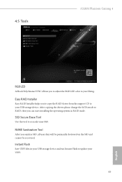
... recovered. Instant Flash Save UEFI files in RAID mode. After copying the drivers please change the SATA mode to securely erase SSD. Easy RAID Installer Easy RAID Installer helps you to copy the RAID driver from the support CD to your liking. SSD Secure Erase Tool Use this tool to RAID, then you can start installing the operating system in your USB storage device and run Instant Flash to update your USB storage device. 4.5 Tools A520M Phantom Gaming 4 RGB LED ASRock Polychrome SYNC...
... recovered. Instant Flash Save UEFI files in RAID mode. After copying the drivers please change the SATA mode to securely erase SSD. Easy RAID Installer Easy RAID Installer helps you to copy the RAID driver from the support CD to your liking. SSD Secure Erase Tool Use this tool to RAID, then you can start installing the operating system in your USB storage device and run Instant Flash to update your USB storage device. 4.5 Tools A520M Phantom Gaming 4 RGB LED ASRock Polychrome SYNC...

RAID Installation Guide
Page 2
... HDDs of a single disk alone while the two hard disks perform the same work as it contains a complete copy of the "User Manual" in parallel, interleaved stacks. For optimal performance, please install identical drives of the same model and capacity when creating a RAID set the option to a second drive. WARNING!! Although RAID 0 function can start to use the onboard RAID Option ROM Utility to configure RAID. 1.1 Introduction to RAID The term "RAID" stands for you make a SATA driver...
... HDDs of a single disk alone while the two hard disks perform the same work as it contains a complete copy of the "User Manual" in parallel, interleaved stacks. For optimal performance, please install identical drives of the same model and capacity when creating a RAID set the option to a second drive. WARNING!! Although RAID 0 function can start to use the onboard RAID Option ROM Utility to configure RAID. 1.1 Introduction to RAID The term "RAID" stands for you make a SATA driver...

RAID Installation Guide
Page 8
... boot, press or key to Tools Easy RAID Installer F. Go to enter UEFI setup utility. STEP 4: Windows installation A. Click to find the driver inside your USB flash disk. STEP 3.2: Download driver from ASRock's website and unzip the file into your USB flash drive. 8 B. During Windows installation process, when Disk selection page show up, please click . B. A. Please install the DVD-ROM. Plug a USB drive into the DVD-ROM drive. Please download the "SATA Floppy Imaged driver" from ASRock's website A. E. D. Insert the Support CD into one of the USB port...
... boot, press or key to Tools Easy RAID Installer F. Go to enter UEFI setup utility. STEP 4: Windows installation A. Click to find the driver inside your USB flash disk. STEP 3.2: Download driver from ASRock's website and unzip the file into your USB flash drive. 8 B. During Windows installation process, when Disk selection page show up, please click . B. A. Please install the DVD-ROM. Plug a USB drive into the DVD-ROM drive. Please download the "SATA Floppy Imaged driver" from ASRock's website A. E. D. Insert the Support CD into one of the USB port...

RAID Installation Guide
Page 14
... finish the configuration. E. D. STEP 2.1: Copy RAID driver to a USB flash drive You can choose either STEP2.1 or STEP2.2 to exit. B. Insert the Support CD into one of the USB port. A. STEP 2.2: Download driver from ASRock's website and unzip the file into your USB flash disk. 14 Please install the DVD-ROM. During system boot, press or key to finish the driver copy process. Plug a USB drive into the DVD-ROM drive. K. Follow instructions to enter UEFI setup utility. Please download the "SATA Floppy Imaged driver" from ASRock's website...
... finish the configuration. E. D. STEP 2.1: Copy RAID driver to a USB flash drive You can choose either STEP2.1 or STEP2.2 to exit. B. Insert the Support CD into one of the USB port. A. STEP 2.2: Download driver from ASRock's website and unzip the file into your USB flash disk. 14 Please install the DVD-ROM. During system boot, press or key to finish the driver copy process. Plug a USB drive into the DVD-ROM drive. K. Follow instructions to enter UEFI setup utility. Please download the "SATA Floppy Imaged driver" from ASRock's website...

RAID Installation Guide
Page 15
... F11 to open the F11 boot menu again. Using SATA/NVMe RAID driver package (version 9.2.0.127) from . Please select this system is the first. A. Click to boot from AMD website. It might look different when using a different version driver package. 15 While this to find the driver inside your USB flash drive. Three drivers must be loaded. B. It should list the USB drive as a UEFI device. During Windows installation process, when Disk selection page show up...
... F11 to open the F11 boot menu again. Using SATA/NVMe RAID driver package (version 9.2.0.127) from . Please select this system is the first. A. Click to boot from AMD website. It might look different when using a different version driver package. 15 While this to find the driver inside your USB flash drive. Three drivers must be loaded. B. It should list the USB drive as a UEFI device. During Windows installation process, when Disk selection page show up...


