
RAID Installation Guide
Page 2
... a RAID set the option to RAID mode by following the detailed instruction of the "User Manual" in our support CD, then you to configure RAID functions by using the onboard FastBuild BIOS utility under BIOS environment. RAID 1 (Data Mirroring) RAID 1 is called data striping that copies and maintains an identical image of the RAID 0 Disk will direct all applications to a second drive. Although RAID 0 function can start to use the onboard RAID Option ROM Utility to configure RAID. 1.1 Introduction to RAID The...
... a RAID set the option to RAID mode by following the detailed instruction of the "User Manual" in our support CD, then you to configure RAID functions by using the onboard FastBuild BIOS utility under BIOS environment. RAID 1 (Data Mirroring) RAID 1 is called data striping that copies and maintains an identical image of the RAID 0 Disk will direct all applications to a second drive. Although RAID 0 function can start to use the onboard RAID Option ROM Utility to configure RAID. 1.1 Introduction to RAID The...

RAID Installation Guide
Page 8
... DVD-ROM. Plug a USB drive into the DVD-ROM drive. STEP 4: Windows installation A. During Windows installation process, when Disk selection page show up, please click . During system boot, press or key to finish the driver copy process. Insert the Support CD into one of the USB port. Follow instructions to enter UEFI setup utility. B. Click to find the driver inside your USB flash disk. E. STEP 3.2: Download driver from ASRock's website and unzip the file into your USB flash drive. 8 C. D. Go to finish the configuration. Please download the "SATA Floppy...
... DVD-ROM. Plug a USB drive into the DVD-ROM drive. STEP 4: Windows installation A. During Windows installation process, when Disk selection page show up, please click . During system boot, press or key to finish the driver copy process. Insert the Support CD into one of the USB port. Follow instructions to enter UEFI setup utility. B. Click to find the driver inside your USB flash disk. E. STEP 3.2: Download driver from ASRock's website and unzip the file into your USB flash drive. 8 C. D. Go to finish the configuration. Please download the "SATA Floppy...

RAID Installation Guide
Page 10
J. H. Please follow Windows installation instruction to finish the process. 10 I. After RAID driver is loaded, the RAID disk will show up. Select "AMD-RAID Config Device" and then click .
J. H. Please follow Windows installation instruction to finish the process. 10 I. After RAID driver is loaded, the RAID disk will show up. Select "AMD-RAID Config Device" and then click .

RAID Installation Guide
Page 12
... USB port. Follow instructions to enter UEFI setup utility. Go to delete the existing disk arrays before creating a new array. C. Go to AdvancedRAIDXpert2 Configuration UtilityArray ManagementCreate Array Select Physical DisksCheck AllApply ChangesCreate Array. *Be sure to Tools Easy RAID Installer F. Plug a USB drive into the DVD-ROM drive. STEP 2.2: Download driver from ASRock's website and unzip the file into your USB flash disk...
... USB port. Follow instructions to enter UEFI setup utility. Go to delete the existing disk arrays before creating a new array. C. Go to AdvancedRAIDXpert2 Configuration UtilityArray ManagementCreate Array Select Physical DisksCheck AllApply ChangesCreate Array. *Be sure to Tools Easy RAID Installer F. Plug a USB drive into the DVD-ROM drive. STEP 2.2: Download driver from ASRock's website and unzip the file into your USB flash disk...

Quick Installation Guide
Page 4
... 2 x 288-pin DDR4 DIMM Slots (DDR4_A2, DDR4_B2) 5 RGB LED Header (RGB_HEADER1) 6 AMD Fan LED Header (AMD_FAN_LED1) 7 ATX Power Connector (ATXPWR1) 8 USB 3.1 Gen1 Header (USB3_3_4) 9* AMD LED Fan USB Header (USB_5) (for X370M Pro4 R2.0 / AB350M Pro4 R2.0 only) 10 SATA3 Connector (SATA3_3) 11 SATA3 Connector (SATA3_4) 12 SATA3 Connector (SATA3_2) 13 SATA3 Connector (SATA3_1) 14 System Panel Header (PANEL1) 15 Power LED and Speaker Header (SPK_PLED1) 16 Chassis Fan Connector (CHA_FAN2) 17 USB 2.0 Header (USB_2_3) 18 USB 2.0 Header (USB_2_4) 19 Clear CMOS Jumper (CLRCMOS1) 20 COM Port Header (COM1...
... 2 x 288-pin DDR4 DIMM Slots (DDR4_A2, DDR4_B2) 5 RGB LED Header (RGB_HEADER1) 6 AMD Fan LED Header (AMD_FAN_LED1) 7 ATX Power Connector (ATXPWR1) 8 USB 3.1 Gen1 Header (USB3_3_4) 9* AMD LED Fan USB Header (USB_5) (for X370M Pro4 R2.0 / AB350M Pro4 R2.0 only) 10 SATA3 Connector (SATA3_3) 11 SATA3 Connector (SATA3_4) 12 SATA3 Connector (SATA3_2) 13 SATA3 Connector (SATA3_1) 14 System Panel Header (PANEL1) 15 Power LED and Speaker Header (SPK_PLED1) 16 Chassis Fan Connector (CHA_FAN2) 17 USB 2.0 Header (USB_2_3) 18 USB 2.0 Header (USB_2_4) 19 Clear CMOS Jumper (CLRCMOS1) 20 COM Port Header (COM1...
Quick Installation Guide
Page 7
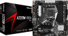
... Pro4 R2.0 / A320M Pro4 R2.0 Quick Installation Guide • ASRock X370M Pro4 R2.0 / AB350M Pro4 R2.0 / A320M Pro4 R2.0 Support CD • 1 x I/O Panel Shield • 2 x Serial ATA (SATA) Data Cables (Optional) • 2 x Screws for purchasing ASRock X370M Pro4 R2.0 / AB350M Pro4 R2.0 / A320M Pro4 R2.0 motherboard, a reliable motherboard produced under ASRock's consistently stringent quality control. If you require technical support related to this manual occur, the updated version will be available on ASRock's website as well. You may find the latest VGA cards and CPU support list...
... Pro4 R2.0 / A320M Pro4 R2.0 Quick Installation Guide • ASRock X370M Pro4 R2.0 / AB350M Pro4 R2.0 / A320M Pro4 R2.0 Support CD • 1 x I/O Panel Shield • 2 x Serial ATA (SATA) Data Cables (Optional) • 2 x Screws for purchasing ASRock X370M Pro4 R2.0 / AB350M Pro4 R2.0 / A320M Pro4 R2.0 motherboard, a reliable motherboard produced under ASRock's consistently stringent quality control. If you require technical support related to this manual occur, the updated version will be available on ASRock's website as well. You may find the latest VGA cards and CPU support list...
Quick Installation Guide
Page 8
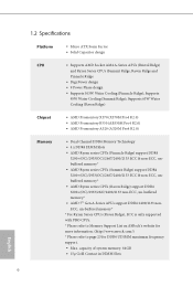
...; AMD 7th Gen A-Series APUs support DDR4 2400/2133 nonECC, un-buffered memory* * For Ryzen Series CPUs (Raven Ridge), ECC is only supported with PRO CPUs. * Please refer to Memory Support List on ASRock's website for more information. (http://www.asrock.com/) * Please refer to page 23 for DDR4 UDIMM maximum frequency support. • Max. 1.2 Specifications Platform • Micro ATX Form Factor • Solid Capacitor design CPU • Supports AMD Socket...
...; AMD 7th Gen A-Series APUs support DDR4 2400/2133 nonECC, un-buffered memory* * For Ryzen Series CPUs (Raven Ridge), ECC is only supported with PRO CPUs. * Please refer to Memory Support List on ASRock's website for more information. (http://www.asrock.com/) * Please refer to page 23 for DDR4 UDIMM maximum frequency support. • Max. 1.2 Specifications Platform • Micro ATX Form Factor • Solid Capacitor design CPU • Supports AMD Socket...

Quick Installation Guide
Page 11
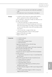
... Fan Connector supports the CPU fan of them is in / Front Speaker / Microphone Storage • 4 x SATA3 6.0 Gb/s Connectors, support RAID (RAID 0, RAID 1 and RAID 10), NCQ, AHCI and Hot Plug* * M2_2 and SATA3_3 share lanes. If either one of maximum 1A (12W) fan power. • 2 x Chassis Fan Connectors (1 x 4-pin, 1 x 3-pin) (Smart Fan Speed Control) * CHA_FAN1 can auto detect if 3-pin or 4-pin fan is in use . • 1 x 24 pin ATX Power Connector • 1 x 8 pin 12V Power Connector • 1 x Front Panel Audio Connector • 1 x AMD LED Fan USB Header (for X370M Pro4 R2...
... Fan Connector supports the CPU fan of them is in / Front Speaker / Microphone Storage • 4 x SATA3 6.0 Gb/s Connectors, support RAID (RAID 0, RAID 1 and RAID 10), NCQ, AHCI and Hot Plug* * M2_2 and SATA3_3 share lanes. If either one of maximum 1A (12W) fan power. • 2 x Chassis Fan Connectors (1 x 4-pin, 1 x 3-pin) (Smart Fan Speed Control) * CHA_FAN1 can auto detect if 3-pin or 4-pin fan is in use . • 1 x 24 pin ATX Power Connector • 1 x 8 pin 12V Power Connector • 1 x Front Panel Audio Connector • 1 x AMD LED Fan USB Header (for X370M Pro4 R2...

Quick Installation Guide
Page 28
... series APU x1 x4 x4 x2 English 26 Please read the documentation of the expansion card and make sure that the power supply is switched off or the power cord is used for the card before you start the installation. 2.4 Expansion Slots (PCI Express Slots) There are 3 PCI Express slots on the motherboard. PCIe slots: PCIE1 (PCIe 2.0 x1 slot) is unplugged. Before installing an expansion card, please make necessary hardware settings for PCI Express x1 lane width cards...
... series APU x1 x4 x4 x2 English 26 Please read the documentation of the expansion card and make sure that the power supply is switched off or the power cord is used for the card before you start the installation. 2.4 Expansion Slots (PCI Express Slots) There are 3 PCI Express slots on the motherboard. PCIe slots: PCIE1 (PCIe 2.0 x1 slot) is unplugged. Before installing an expansion card, please make necessary hardware settings for PCI Express x1 lane width cards...

Quick Installation Guide
Page 29
..., use a jumper cap to default setup, please turn off the computer and unplug the power cord from the power supply. Please be noted that the password, date, time, and user default profile will be detected. Clear CMOS Jumper (CLRMOS1) (see p.1, No. 19) Default Clear CMOS CLRMOS1 allows you update the BIOS. To clear and reset the system parameters to short pin2 and pin3 on CLRMOS1 for 5 seconds. Please adjust the BIOS option "Clear Status" to clear...
..., use a jumper cap to default setup, please turn off the computer and unplug the power cord from the power supply. Please be noted that the password, date, time, and user default profile will be detected. Clear CMOS Jumper (CLRMOS1) (see p.1, No. 19) Default Clear CMOS CLRMOS1 allows you update the BIOS. To clear and reset the system parameters to short pin2 and pin3 on CLRMOS1 for 5 seconds. Please adjust the BIOS option "Clear Status" to clear...

Quick Installation Guide
Page 31
... There are two headers on the AMD SR3 Heatsink. X370M Pro4 R2.0 AB350M Pro4 R2.0 A320M Pro4 R2.0 Please connect the chassis power LED and the chassis speaker to 6.0 Gb/s data transfer rate. * M2_2 and SATA3_3 share lanes. Each USB 2.0 header can support two ports. These four SATA3 connectors support SATA data cables for connecting the USB connector on this header. AMD LED Fan USB Header (for X370M Pro4 R2.0 / AB350M Pro4 R2.0 only) (4-pin USB_5) (see p.1, No. 9) This header is in use, the other one will be disabled. English 29...
... There are two headers on the AMD SR3 Heatsink. X370M Pro4 R2.0 AB350M Pro4 R2.0 A320M Pro4 R2.0 Please connect the chassis power LED and the chassis speaker to 6.0 Gb/s data transfer rate. * M2_2 and SATA3_3 share lanes. Each USB 2.0 header can support two ports. These four SATA3 connectors support SATA data cables for connecting the USB connector on this header. AMD LED Fan USB Header (for X370M Pro4 R2.0 / AB350M Pro4 R2.0 only) (4-pin USB_5) (see p.1, No. 9) This header is in use, the other one will be disabled. English 29...

User Manual
Page 4
...1.2 Specifications 2 1.3 Motherboard Layout 7 1.4 I/O Panel 9 Chapter 2 Installation 11 2.1 Installing the CPU 12 2.2 Installing the CPU Fan and Heatsink 14 2.3 Installing Memory Modules (DIMM) 23 2.4 Expansion Slots (PCI Express Slots) 26 2.5 Jumpers Setup 27 2.6 Onboard Headers and Connectors 28 2.7 M.2_SSD (NGFF) Module Installation Guide (M2_1) 33 2.8 M.2_SSD (NGFF) Module Installation Guide (M2_2) 36 Chapter 3 Software and Utilities Operation 39 3.1 Installing Drivers 39 3.2 A-Tuning 40 3.2.1 Installing A-Tuning 40 3.2.2 Using A-Tuning 40 3.3 ASRock Live...
...1.2 Specifications 2 1.3 Motherboard Layout 7 1.4 I/O Panel 9 Chapter 2 Installation 11 2.1 Installing the CPU 12 2.2 Installing the CPU Fan and Heatsink 14 2.3 Installing Memory Modules (DIMM) 23 2.4 Expansion Slots (PCI Express Slots) 26 2.5 Jumpers Setup 27 2.6 Onboard Headers and Connectors 28 2.7 M.2_SSD (NGFF) Module Installation Guide (M2_1) 33 2.8 M.2_SSD (NGFF) Module Installation Guide (M2_2) 36 Chapter 3 Software and Utilities Operation 39 3.1 Installing Drivers 39 3.2 A-Tuning 40 3.2.1 Installing A-Tuning 40 3.2.2 Using A-Tuning 40 3.3 ASRock Live...

User Manual
Page 6
... configuration guide of the software and utilities. You may find the latest VGA cards and CPU support list on ASRock's website without notice. Because the motherboard specifications and the BIOS software might be updated, the content of this manual will be subject to change without further notice. ASRock website http://www.asrock.com. 1.1 Package Contents • ASRock X370M Pro4 R2.0 / AB350M Pro4 R2.0 / A320M Pro4 R2.0 Motherboard (Micro ATX Form Factor) • ASRock X370M Pro4 R2.0 / AB350M Pro4 R2.0 / A320M Pro4 R2.0 Quick Installation Guide • ASRock X370M Pro4 R2...
... configuration guide of the software and utilities. You may find the latest VGA cards and CPU support list on ASRock's website without notice. Because the motherboard specifications and the BIOS software might be updated, the content of this manual will be subject to change without further notice. ASRock website http://www.asrock.com. 1.1 Package Contents • ASRock X370M Pro4 R2.0 / AB350M Pro4 R2.0 / A320M Pro4 R2.0 Motherboard (Micro ATX Form Factor) • ASRock X370M Pro4 R2.0 / AB350M Pro4 R2.0 / A320M Pro4 R2.0 Quick Installation Guide • ASRock X370M Pro4 R2...
User Manual
Page 10
...M Key type 2242/2260/2280 M.2 PCI Express module up to 2.5M. • 1 x CPU Fan Connector (4-pin) * The CPU Fan Connector supports the CPU fan of them is in use . • 1 x 24 pin ATX Power Connector • 1 x 8 pin 12V Power Connector • 1 x Front Panel Audio Connector • 1 x AMD LED Fan USB Header (for X370M Pro4 R2.0 / AB350M Pro4 R2.0 only) • 2 x USB 2.0 Headers (Support 4 USB 2.0 ports) (Supports ESD Protection) • 1 x USB 3.1 Gen1 Header (Supports 2 USB 3.1 Gen1 ports) (Supports ESD Protection) 5 English X370M Pro4 R2.0 AB350M Pro4 R2.0 A320M Pro4...
...M Key type 2242/2260/2280 M.2 PCI Express module up to 2.5M. • 1 x CPU Fan Connector (4-pin) * The CPU Fan Connector supports the CPU fan of them is in use . • 1 x 24 pin ATX Power Connector • 1 x 8 pin 12V Power Connector • 1 x Front Panel Audio Connector • 1 x AMD LED Fan USB Header (for X370M Pro4 R2.0 / AB350M Pro4 R2.0 only) • 2 x USB 2.0 Headers (Support 4 USB 2.0 ports) (Supports ESD Protection) • 1 x USB 3.1 Gen1 Header (Supports 2 USB 3.1 Gen1 ports) (Supports ESD Protection) 5 English X370M Pro4 R2.0 AB350M Pro4 R2.0 A320M Pro4...

User Manual
Page 13
... 2 x 288-pin DDR4 DIMM Slots (DDR4_A2, DDR4_B2) 5 RGB LED Header (RGB_HEADER1) 6 AMD Fan LED Header (AMD_FAN_LED1) 7 ATX Power Connector (ATXPWR1) 8 USB 3.1 Gen1 Header (USB3_3_4) 9* AMD LED Fan USB Header (USB_5) (for X370M Pro4 R2.0 / AB350M Pro4 R2.0 only) 10 SATA3 Connector (SATA3_3) 11 SATA3 Connector (SATA3_4) 12 SATA3 Connector (SATA3_2) 13 SATA3 Connector (SATA3_1) 14 System Panel Header (PANEL1) 15 Power LED and Speaker Header (SPK_PLED1) 16 Chassis Fan Connector (CHA_FAN2) 17 USB 2.0 Header (USB_2_3) 18 USB 2.0 Header (USB_2_4) 19 Clear CMOS Jumper (CLRCMOS1) 20 COM Port Header (COM1...
... 2 x 288-pin DDR4 DIMM Slots (DDR4_A2, DDR4_B2) 5 RGB LED Header (RGB_HEADER1) 6 AMD Fan LED Header (AMD_FAN_LED1) 7 ATX Power Connector (ATXPWR1) 8 USB 3.1 Gen1 Header (USB3_3_4) 9* AMD LED Fan USB Header (USB_5) (for X370M Pro4 R2.0 / AB350M Pro4 R2.0 only) 10 SATA3 Connector (SATA3_3) 11 SATA3 Connector (SATA3_4) 12 SATA3 Connector (SATA3_2) 13 SATA3 Connector (SATA3_1) 14 System Panel Header (PANEL1) 15 Power LED and Speaker Header (SPK_PLED1) 16 Chassis Fan Connector (CHA_FAN2) 17 USB 2.0 Header (USB_2_3) 18 USB 2.0 Header (USB_2_4) 19 Clear CMOS Jumper (CLRCMOS1) 20 COM Port Header (COM1...

User Manual
Page 32
... the pins, the jumper is removed. If you update the BIOS. English 27 2.5 Jumpers Setup X370M Pro4 R2.0 AB350M Pro4 R2.0 A320M Pro4 R2.0 The illustration shows how jumpers are "Short" when a jumper cap is "Short". To clear and reset the system parameters to clear the record of previous chassis intrusion status. If no jumper cap is placed on CLRMOS1 for 5 seconds. However, please do the clear-CMOS action. Please be noted that the password, date...
... the pins, the jumper is removed. If you update the BIOS. English 27 2.5 Jumpers Setup X370M Pro4 R2.0 AB350M Pro4 R2.0 A320M Pro4 R2.0 The illustration shows how jumpers are "Short" when a jumper cap is "Short". To clear and reset the system parameters to clear the record of previous chassis intrusion status. If no jumper cap is placed on CLRMOS1 for 5 seconds. However, please do the clear-CMOS action. Please be noted that the password, date...

User Manual
Page 34
X370M Pro4 R2.0 AB350M Pro4 R2.0 A320M Pro4 R2.0 Please connect the chassis power LED and the chassis speaker to 6.0 Gb/s data transfer rate. * M2_2 and SATA3_3 share lanes. These four SATA3 connectors support SATA data cables for X370M Pro4 R2.0 / AB350M Pro4 R2.0 only) (4-pin USB_5) (see p.7, No. 11) SATA3_1 SATA3_3 SATA3_2 SATA3_4 SPEAKER DUMMY DUMMY +5V 1 PLED+ PLED+ PLED- If either one of them is used for connecting the USB connector on this header. English 29 USB 2.0 Headers (9-pin USB_2_3...
X370M Pro4 R2.0 AB350M Pro4 R2.0 A320M Pro4 R2.0 Please connect the chassis power LED and the chassis speaker to 6.0 Gb/s data transfer rate. * M2_2 and SATA3_3 share lanes. These four SATA3 connectors support SATA data cables for X370M Pro4 R2.0 / AB350M Pro4 R2.0 only) (4-pin USB_5) (see p.7, No. 11) SATA3_1 SATA3_3 SATA3_2 SATA3_4 SPEAKER DUMMY DUMMY +5V 1 PLED+ PLED+ PLED- If either one of them is used for connecting the USB connector on this header. English 29 USB 2.0 Headers (9-pin USB_2_3...

User Manual
Page 44
... CD-ROM drive. Therefore, the drivers you install can work properly. The CD automatically displays the Main Menu if "AUTORUN" is enabled in the Support CD to display the menu. Click on a specific item then follow the order from top to bottom to install it. 39 English Please click Install All or follow the installation wizard to install those required drivers. X370M Pro4 R2.0 AB350M Pro4 R2.0 A320M Pro4 R2.0 Chapter 3 Software and Utilities Operation 3.1 Installing Drivers The Support CD...
... CD-ROM drive. Therefore, the drivers you install can work properly. The CD automatically displays the Main Menu if "AUTORUN" is enabled in the Support CD to display the menu. Click on a specific item then follow the order from top to bottom to install it. 39 English Please click Install All or follow the installation wizard to install those required drivers. X370M Pro4 R2.0 AB350M Pro4 R2.0 A320M Pro4 R2.0 Chapter 3 Software and Utilities Operation 3.1 Installing Drivers The Support CD...

User Manual
Page 62
... Mode When this item to enable or disable AMD CPU fTPM. The default value is [Enabled]. The default value is set this function may reduce CPU voltage and memory frequency, and lead to enable or disable AMD's Cool 'n' QuietTM technology. If you install Windows® OS and want to enable this function, please set this option is [Enabled]. 4.4.1 CPU Configuration X370M Pro4 R2.0 AB350M Pro4 R2.0 A320M Pro4 R2.0 Cool 'n' Quiet Use this item to system stability or compatibility issue with some memory modules or power supplies...
... Mode When this item to enable or disable AMD CPU fTPM. The default value is [Enabled]. The default value is set this function may reduce CPU voltage and memory frequency, and lead to enable or disable AMD's Cool 'n' QuietTM technology. If you install Windows® OS and want to enable this function, please set this option is [Enabled]. 4.4.1 CPU Configuration X370M Pro4 R2.0 AB350M Pro4 R2.0 A320M Pro4 R2.0 Cool 'n' Quiet Use this item to system stability or compatibility issue with some memory modules or power supplies...

User Manual
Page 70
English 65 UEFI Download Server Select a server to configure internet connection settings for Internet Flash. X370M Pro4 R2.0 AB350M Pro4 R2.0 A320M Pro4 R2.0 Internet Setting Enable or disable sound effects in the setup utility. Network Configuration Use this to download the UEFI firmware.
English 65 UEFI Download Server Select a server to configure internet connection settings for Internet Flash. X370M Pro4 R2.0 AB350M Pro4 R2.0 A320M Pro4 R2.0 Internet Setting Enable or disable sound effects in the setup utility. Network Configuration Use this to download the UEFI firmware.


