RAID Installation Guide
Page 2
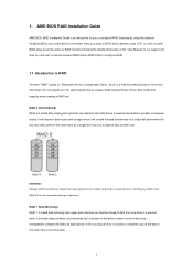
... the access performance, it will cause data damage or data loss. RAID 0 (Data Striping) RAID 0 is called data striping that copies and maintains an identical image of the same model and capacity when creating a RAID set the option to RAID mode by using the onboard FastBuild BIOS utility under BIOS environment. Hot-Plug any fault tolerance. 1. Although RAID 0 function can start to use the onboard RAID Option ROM Utility to configure RAID. 1.1 Introduction to a second drive.
... the access performance, it will cause data damage or data loss. RAID 0 (Data Striping) RAID 0 is called data striping that copies and maintains an identical image of the same model and capacity when creating a RAID set the option to RAID mode by using the onboard FastBuild BIOS utility under BIOS environment. Hot-Plug any fault tolerance. 1. Although RAID 0 function can start to use the onboard RAID Option ROM Utility to configure RAID. 1.1 Introduction to a second drive.
RAID Installation Guide
Page 8
... USB flash drive. 8 Click to find the driver inside your USB flash disk. A. During system boot, press or key to finish the driver copy process. Insert the Support CD into one of the USB port. Follow instructions to enter UEFI setup utility. STEP 4: Windows installation A. Plug a USB drive into the DVD-ROM drive. Go to finish the configuration. During Windows installation process, when Disk selection page show up, please click . D. B. C. Please download the "SATA Floppy Imaged driver" from ASRock's website A. STEP 3.1: Copy RAID driver to a USB flash drive...
... USB flash drive. 8 Click to find the driver inside your USB flash disk. A. During system boot, press or key to finish the driver copy process. Insert the Support CD into one of the USB port. Follow instructions to enter UEFI setup utility. STEP 4: Windows installation A. Plug a USB drive into the DVD-ROM drive. Go to finish the configuration. During Windows installation process, when Disk selection page show up, please click . D. B. C. Please download the "SATA Floppy Imaged driver" from ASRock's website A. STEP 3.1: Copy RAID driver to a USB flash drive...
RAID Installation Guide
Page 12
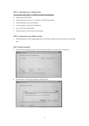
... RAID driver to a USB flash drive You can choose either STEP2.1 or STEP2.2 to enter UEFI setup utility. During system boot, press or key to finish the configuration. D. Follow instructions to exit. C. Click to save to finish the driver copy process. A. B. Please install the DVD-ROM. Please download the "SATA Floppy Imaged driver" from ASRock's website A. Go to delete the existing disk arrays before creating a new array. Plug a USB drive into your USB flash disk. 12 Insert the Support CD...
... RAID driver to a USB flash drive You can choose either STEP2.1 or STEP2.2 to enter UEFI setup utility. During system boot, press or key to finish the configuration. D. Follow instructions to exit. C. Click to save to finish the driver copy process. A. B. Please install the DVD-ROM. Please download the "SATA Floppy Imaged driver" from ASRock's website A. Go to delete the existing disk arrays before creating a new array. Plug a USB drive into your USB flash disk. 12 Insert the Support CD...
User Manual
Page 4
... 1 1.2 Specifications 2 1.3 Motherboard Layout 7 Chapter 2 Installation 10 2.1 Installing the CPU 11 2.2 Installing the CPU Fan and Heatsink 13 2.3 Installing Memory Modules (DIMM) 21 2.4 Expansion Slots (PCI and PCI Express Slots) 25 2.5 Jumpers Setup 26 2.6 Onboard Headers and Connectors 27 2.7 M.2_SSD (NGFF) Module Installation Guide 31 Chapter 3 Software and Utilities Operation 35 3.1 Installing Drivers 35 3.2 ASRock Live Update & APP Shop 36 3.2.1 UI Overview 36 3.2.2 Apps 37 3.2.3 BIOS & Drivers 40 3.2.4 Setting 41 Chapter 4 UEFI SETUP UTILITY 42...
... 1 1.2 Specifications 2 1.3 Motherboard Layout 7 Chapter 2 Installation 10 2.1 Installing the CPU 11 2.2 Installing the CPU Fan and Heatsink 13 2.3 Installing Memory Modules (DIMM) 21 2.4 Expansion Slots (PCI and PCI Express Slots) 25 2.5 Jumpers Setup 26 2.6 Onboard Headers and Connectors 27 2.7 M.2_SSD (NGFF) Module Installation Guide 31 Chapter 3 Software and Utilities Operation 35 3.1 Installing Drivers 35 3.2 ASRock Live Update & APP Shop 36 3.2.1 UI Overview 36 3.2.2 Apps 37 3.2.3 BIOS & Drivers 40 3.2.4 Setting 41 Chapter 4 UEFI SETUP UTILITY 42...
User Manual
Page 6
...Motherboard (Micro ATX Form Factor) • ASRock A320M-HDVP Quick Installation Guide • ASRock A320M-HDVP Support CD • 1 x I/O Panel Shield • 2 x Serial ATA (SATA) Data Cables (Optional) • 1 x Screw for purchasing ASRock A320M-HDVP motherboard, a reliable motherboard produced under ASRock's consistently stringent quality control. In this manual will be updated, the content of the software and utilities. You may find the latest VGA cards and CPU support list on ASRock's website without notice. Because the motherboard specifications and the BIOS software...
...Motherboard (Micro ATX Form Factor) • ASRock A320M-HDVP Quick Installation Guide • ASRock A320M-HDVP Support CD • 1 x I/O Panel Shield • 2 x Serial ATA (SATA) Data Cables (Optional) • 1 x Screw for purchasing ASRock A320M-HDVP motherboard, a reliable motherboard produced under ASRock's consistently stringent quality control. In this manual will be updated, the content of the software and utilities. You may find the latest VGA cards and CPU support list on ASRock's website without notice. Because the motherboard specifications and the BIOS software...
User Manual
Page 8
... (High Bit Rate Audio) with HDMI 1.4 Port (Compliant HDMI monitor is required) • Supports HDCP 1.4 with DVI-D and HDMI 1.4 Ports • Supports Full HD 1080p Blu-ray (BD) playback with max. A320M-HDVP Expansion Slot AMD Ryzen series CPUs (Matisse, Summit Ridge and Pinnacle Ridge) • 1 x PCI Express 3.0 x16 Slot (PCIE2: x16 mode)* AMD 7th A-Series APUs • 1 x PCI Express 3.0 x16 Slot (PCIE2: x8 mode)* AMD Ryzen series CPUs (Picasso, Raven Ridge) • 1 x PCI Express 3.0 x16 Slot (PCIE2: x8 mode)* AMD Athlon series CPUs • 1 x PCI Express...
... (High Bit Rate Audio) with HDMI 1.4 Port (Compliant HDMI monitor is required) • Supports HDCP 1.4 with DVI-D and HDMI 1.4 Ports • Supports Full HD 1080p Blu-ray (BD) playback with max. A320M-HDVP Expansion Slot AMD Ryzen series CPUs (Matisse, Summit Ridge and Pinnacle Ridge) • 1 x PCI Express 3.0 x16 Slot (PCIE2: x16 mode)* AMD 7th A-Series APUs • 1 x PCI Express 3.0 x16 Slot (PCIE2: x8 mode)* AMD Ryzen series CPUs (Picasso, Raven Ridge) • 1 x PCI Express 3.0 x16 Slot (PCIE2: x8 mode)* AMD Athlon series CPUs • 1 x PCI Express...
User Manual
Page 9
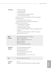
... • Supports PXE Rear Panel I/O • 1 x PS/2 Mouse Port • 1 x PS/2 Keyboard Port • 1 x Serial Port: COM1 • 1 x D-Sub Port • 1 x DVI-D Port • 1 x HDMI Port • 2 x USB 2.0 Ports (Supports ESD Protection) • 4 x USB 3.2 Gen1 Ports (Supports ESD Protection) • 1 x RJ-45 LAN Port with LED (ACT/LINK LED and SPEED LED) • HD Audio Jacks: Line in / Front Speaker / Microphone Storage • 4 x SATA3 6.0 Gb/s Connectors, support RAID (RAID 0, RAID 1 and RAID 10), NCQ, AHCI and Hot Plug • 1 x Ultra M.2 Socket, supports M Key type 2242...
... • Supports PXE Rear Panel I/O • 1 x PS/2 Mouse Port • 1 x PS/2 Keyboard Port • 1 x Serial Port: COM1 • 1 x D-Sub Port • 1 x DVI-D Port • 1 x HDMI Port • 2 x USB 2.0 Ports (Supports ESD Protection) • 4 x USB 3.2 Gen1 Ports (Supports ESD Protection) • 1 x RJ-45 LAN Port with LED (ACT/LINK LED and SPEED LED) • HD Audio Jacks: Line in / Front Speaker / Microphone Storage • 4 x SATA3 6.0 Gb/s Connectors, support RAID (RAID 0, RAID 1 and RAID 10), NCQ, AHCI and Hot Plug • 1 x Ultra M.2 Socket, supports M Key type 2242...
User Manual
Page 10
... x 24 pin ATX Power Connector • 1 x 4 pin 12V Power Connector • 1 x Front Panel Audio Connector • 2 x USB 2.0 Headers (Support 4 USB 2.0 ports) (Supports ESD Protection) • 1 x USB 3.2 Gen1 Header (Supports 2 USB 3.2 Gen1 ports) (Supports ESD Protection) BIOS Feature • AMI UEFI Legal BIOS with GUI support • Supports "Plug and Play" • ACPI 5.1 compliance wake up events • Supports jumperfree • SMBIOS 2.3 support • DRAM Voltage multi-adjustment Hardware Monitor • CPU/Chassis temperature sensing • CPU/Chassis Fan Tachometer...
... x 24 pin ATX Power Connector • 1 x 4 pin 12V Power Connector • 1 x Front Panel Audio Connector • 2 x USB 2.0 Headers (Support 4 USB 2.0 ports) (Supports ESD Protection) • 1 x USB 3.2 Gen1 Header (Supports 2 USB 3.2 Gen1 ports) (Supports ESD Protection) BIOS Feature • AMI UEFI Legal BIOS with GUI support • Supports "Plug and Play" • ACPI 5.1 compliance wake up events • Supports jumperfree • SMBIOS 2.3 support • DRAM Voltage multi-adjustment Hardware Monitor • CPU/Chassis temperature sensing • CPU/Chassis Fan Tachometer...
User Manual
Page 12
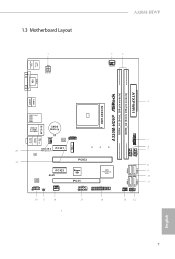
... PS2 Keyboard 1.3 Motherboard Layout 1 ATX12V A320M-HDVP 2 3 CPU_FAN1 DVI1 VGA A320M-HDVP DDR4_A1 (64 bit, 288-FpinSBmo8d0ul0e) DDR4_A2 (64 bit, 288-pin module) ATXPWR1 SOCKET AM4 COM1 HDMI1 4 USB 3.1 Gen1 USB1 USB2 USB3 USB4 RJ-45 LAN USB 2.0 T: USB1 B: USB2 CMOS Battery SPI_TPM_J1 CHA_FAN1 BIOS 1 5 ROM USB3_5_6 Top: LINE IN Center: FRONT Bottom: MIC IN Ultra M.2 PCIE1 20 PCIe Gen3 x4 LAN PCIE2 19 M2_1 1 6 7 USB_3_4 USB_5_6 1 1 8 SATA3_4 SATA3_3 PCIE3 Super AMD...
... PS2 Keyboard 1.3 Motherboard Layout 1 ATX12V A320M-HDVP 2 3 CPU_FAN1 DVI1 VGA A320M-HDVP DDR4_A1 (64 bit, 288-FpinSBmo8d0ul0e) DDR4_A2 (64 bit, 288-pin module) ATXPWR1 SOCKET AM4 COM1 HDMI1 4 USB 3.1 Gen1 USB1 USB2 USB3 USB4 RJ-45 LAN USB 2.0 T: USB1 B: USB2 CMOS Battery SPI_TPM_J1 CHA_FAN1 BIOS 1 5 ROM USB3_5_6 Top: LINE IN Center: FRONT Bottom: MIC IN Ultra M.2 PCIE1 20 PCIe Gen3 x4 LAN PCIE2 19 M2_1 1 6 7 USB_3_4 USB_5_6 1 1 8 SATA3_4 SATA3_3 PCIE3 Super AMD...
User Manual
Page 13
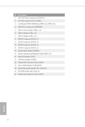
...Power Connector (ATX12V1) 2 CPU Fan Connector (CPU_FAN1) 3 2 x 288-pin DDR4 DIMM Slots (DDR4_A1, DDR4_A2) 4 ATX Power Connector (ATXPWR1) 5 USB 3.2 Gen1 Header (USB3_5_6) 6 USB 2.0 Header (USB_3_4) 7 USB 2.0 Header (USB_5_6) 8 SATA3 Connector (SATA3_3) 9 SATA3 Connector (SATA3_4) 10 SATA3 Connector (SATA3_1) 11 SATA3 Connector (SATA3_2) 12 System Panel Header (PANEL1) 13 Chassis Intrusion and Speaker Header (SPK_CI1) 14 Print Port Header (LPT1) 15 COM Port Header (COM2) 16 Chassis Fan Connector (CHA_FAN2) 17 Clear CMOS Header (CLRCMOS1) 18 Front Panel Audio Header (HD_AUDIO1) 19 SPI TPM Header...
...Power Connector (ATX12V1) 2 CPU Fan Connector (CPU_FAN1) 3 2 x 288-pin DDR4 DIMM Slots (DDR4_A1, DDR4_A2) 4 ATX Power Connector (ATXPWR1) 5 USB 3.2 Gen1 Header (USB3_5_6) 6 USB 2.0 Header (USB_3_4) 7 USB 2.0 Header (USB_5_6) 8 SATA3 Connector (SATA3_3) 9 SATA3 Connector (SATA3_4) 10 SATA3 Connector (SATA3_1) 11 SATA3 Connector (SATA3_2) 12 System Panel Header (PANEL1) 13 Chassis Intrusion and Speaker Header (SPK_CI1) 14 Print Port Header (LPT1) 15 COM Port Header (COM2) 16 Chassis Fan Connector (CHA_FAN2) 17 Clear CMOS Header (CLRCMOS1) 18 Front Panel Audio Header (HD_AUDIO1) 19 SPI TPM Header...
User Manual
Page 30
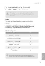
... PCI Express x1 lane width cards PCIe Slot Configurations CPU Ryzen series CPUs (Matisse) Ryzen series CPUs (Pinnacle Ridge) PCIE2 x16 x16 Ryzen series CPUs (Summit Ridge) x16 Ryzen series CPUs (Picasso) x8 Ryzen series CPUs (Raven Ridge) x8 7th A-Series APUs x4 For a better thermal environment, please connect a chassis fan to install expansion cards that the power supply is switched off or the power cord is used for the card before you start the installation...
... PCI Express x1 lane width cards PCIe Slot Configurations CPU Ryzen series CPUs (Matisse) Ryzen series CPUs (Pinnacle Ridge) PCIE2 x16 x16 Ryzen series CPUs (Summit Ridge) x16 Ryzen series CPUs (Picasso) x8 Ryzen series CPUs (Raven Ridge) x8 7th A-Series APUs x4 For a better thermal environment, please connect a chassis fan to install expansion cards that the power supply is switched off or the power cord is used for the card before you start the installation...
User Manual
Page 31
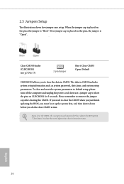
Clear CMOS Header (CLRCMOS1) (see p.7, No. 17) 2-pin Jumper Short: Clear CMOS Open: Default CLRCMOS1 allows you need to clear the record of previous chassis intrusion status. The data in CMOS. If no jumper cap is placed on the pins, the jumper is "Open". To clear and reset the system parameters to default setup, please turn off the computer and unplug the power cord, then use a jumper cap to remove the jumper cap after clearing the CMOS. Please...
Clear CMOS Header (CLRCMOS1) (see p.7, No. 17) 2-pin Jumper Short: Clear CMOS Open: Default CLRCMOS1 allows you need to clear the record of previous chassis intrusion status. The data in CMOS. If no jumper cap is placed on the pins, the jumper is "Open". To clear and reset the system parameters to default setup, please turn off the computer and unplug the power cord, then use a jumper cap to remove the jumper cap after clearing the CMOS. Please...

User Manual
Page 32
... chassis front panel module to this header according to the hard drive activity LED on the chassis front panel. Do NOT place jumper caps over the headers and connectors will cause permanent damage to the reset button on the chassis front panel. RESET (Reset Button): Connect to the motherboard. The LED is reading or writing data. You may differ by chassis. When connecting your system using the power button. PWRBTN (Power Button): Connect to perform a normal restart. A320M-HDVP 2.6 Onboard Headers and Connectors Onboard headers and connectors...
... chassis front panel module to this header according to the hard drive activity LED on the chassis front panel. Do NOT place jumper caps over the headers and connectors will cause permanent damage to the reset button on the chassis front panel. RESET (Reset Button): Connect to the motherboard. The LED is reading or writing data. You may differ by chassis. When connecting your system using the power button. PWRBTN (Power Button): Connect to perform a normal restart. A320M-HDVP 2.6 Onboard Headers and Connectors Onboard headers and connectors...
User Manual
Page 33
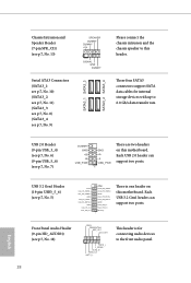
... the chassis speaker to this motherboard. These four SATA3 connectors support SATA data cables for connecting audio devices to 6.0 Gb/s data transfer rate. USB 2.0 Header (9-pin USB_3_4) (see p.7, No. 6) (9-pin USB_5_6) (see p.7, No. 5) Vbus IntA_PA_SSRXIntA_PA_SSRX+ GND IntA_PA_SSTXIntA_PA_SSTX+ GND IntA_PA_DIntA_PA_D+ Vbus IntA_PB_SSRXIntA_PB_SSRX+ GND IntA_PB_SSTXIntA_PB_SSTX+ GND IntA_PB_DIntA_PB_D+ Dummy 1 There is for internal storage devices with up to the front audio panel. 28 English Each USB 2.0 header can support two ports. USB 3.2 Gen1 Header (19-pin USB3_5_6...
... the chassis speaker to this motherboard. These four SATA3 connectors support SATA data cables for connecting audio devices to 6.0 Gb/s data transfer rate. USB 2.0 Header (9-pin USB_3_4) (see p.7, No. 6) (9-pin USB_5_6) (see p.7, No. 5) Vbus IntA_PA_SSRXIntA_PA_SSRX+ GND IntA_PA_SSTXIntA_PA_SSTX+ GND IntA_PA_DIntA_PA_D+ Vbus IntA_PB_SSRXIntA_PB_SSRX+ GND IntA_PB_SSTXIntA_PB_SSTX+ GND IntA_PB_DIntA_PB_D+ Dummy 1 There is for internal storage devices with up to the front audio panel. 28 English Each USB 2.0 header can support two ports. USB 3.2 Gen1 Header (19-pin USB3_5_6...
User Manual
Page 34
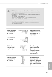
... Realtek Control panel and adjust "Recording Volume". MIC_RET and OUT_RET are for the AC'97 audio panel. Chassis Fan Connector (4-pin CHA_FAN1) (see p.7, No. 20) (4-pin CHA_FAN2) (see p.7, No. 4) FAN_SPEED_CONTROL CPU_FAN_SPEED FAN_VOLTAGE GND 1 2 34 12 24 1 13 This motherboard provides a 4-Pin CPU fan (Quiet Fan) connector. This motherboard provides a 24-pin ATX power connector. C. To activate the front mic, go to function correctly. If you plan to the ground pin. A320M-HDVP 1. High Definition Audio supports...
... Realtek Control panel and adjust "Recording Volume". MIC_RET and OUT_RET are for the AC'97 audio panel. Chassis Fan Connector (4-pin CHA_FAN1) (see p.7, No. 20) (4-pin CHA_FAN2) (see p.7, No. 4) FAN_SPEED_CONTROL CPU_FAN_SPEED FAN_VOLTAGE GND 1 2 34 12 24 1 13 This motherboard provides a 4-Pin CPU fan (Quiet Fan) connector. This motherboard provides a 24-pin ATX power connector. C. To activate the front mic, go to function correctly. If you plan to the ground pin. A320M-HDVP 1. High Definition Audio supports...
User Manual
Page 40
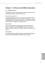
... the file "ASRSETUP.EXE" in your CD-ROM drive. Drivers Menu The drivers compatible to display the menu. Utilities Menu The Utilities Menu shows the application software that enhance the motherboard's features. If the Main Menu does not appear automatically, locate and double click on a specific item then follow the order from top to bottom to install it. 35 English Therefore, the drivers you install can work properly. A320M-HDVP Chapter 3 Software and Utilities Operation 3.1 Installing Drivers The Support CD...
... the file "ASRSETUP.EXE" in your CD-ROM drive. Drivers Menu The drivers compatible to display the menu. Utilities Menu The Utilities Menu shows the application software that enhance the motherboard's features. If the Main Menu does not appear automatically, locate and double click on a specific item then follow the order from top to bottom to install it. 35 English Therefore, the drivers you install can work properly. A320M-HDVP Chapter 3 Software and Utilities Operation 3.1 Installing Drivers The Support CD...
User Manual
Page 47
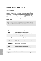
... power on . Because the UEFI software is constantly being updated, the following selections: Main For setting system time/date information OC Tweaker For overclocking configurations Advanced For advanced system configurations Tool Useful tools H/W Monitor Displays current hardware status Boot For configuring boot settings and boot priority Security For security settings Exit Exit the current screen or the UEFI Setup Utility English 42 You may also restart by pressing the reset button on the system chassis...
... power on . Because the UEFI software is constantly being updated, the following selections: Main For setting system time/date information OC Tweaker For overclocking configurations Advanced For advanced system configurations Tool Useful tools H/W Monitor Displays current hardware status Boot For configuring boot settings and boot priority Security For security settings Exit Exit the current screen or the UEFI Setup Utility English 42 You may also restart by pressing the reset button on the system chassis...
User Manual
Page 50
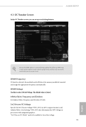
DRAM Voltage Use this voltage. 45 English Infinity Fabric Frequency and Dividers Set Infinity Fabric Frequency and Dividers (FCLK). DRAM Frequency If [Auto] is [Auto]. 4.3 OC Tweaker Screen In the OC Tweaker screen, you see on processors with integrated graphics. A320M-HDVP Because the UEFI software is constantly being updated, the following UEFI setup screens and descriptions are for reference purpose only, and they may not exactly match what you can set up overclocking features. VDD_SOC...
DRAM Voltage Use this voltage. 45 English Infinity Fabric Frequency and Dividers Set Infinity Fabric Frequency and Dividers (FCLK). DRAM Frequency If [Auto] is [Auto]. 4.3 OC Tweaker Screen In the OC Tweaker screen, you see on processors with integrated graphics. A320M-HDVP Because the UEFI software is constantly being updated, the following UEFI setup screens and descriptions are for reference purpose only, and they may not exactly match what you can set up overclocking features. VDD_SOC...
User Manual
Page 53
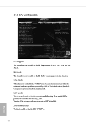
... re-enable SMT, a power cycle is [Enabled]. SVM Mode When this to disable symmetric multithreading. The default value is needed after selecting [Auto]. 4.4.1 CPU Configuration PSS Support This item allows you to enable or disable the generation of ACPI_PPC, _PSS, and _PCT objects. Coniguration options: [Enabled] and [Disabled]. Warning: S3 is not supported on systems where SMT is set to [Enabled], a VMM (Virtual Machine Architecture)can be used to enable or disable AMD CPU...
... re-enable SMT, a power cycle is [Enabled]. SVM Mode When this to disable symmetric multithreading. The default value is needed after selecting [Auto]. 4.4.1 CPU Configuration PSS Support This item allows you to enable or disable the generation of ACPI_PPC, _PSS, and _PCT objects. Coniguration options: [Enabled] and [Disabled]. Warning: S3 is not supported on systems where SMT is set to [Enabled], a VMM (Virtual Machine Architecture)can be used to enable or disable AMD CPU...
User Manual
Page 65
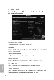
... onboard LAN. Disable for faster boot speed. 60 English Setup Prompt Timeout Configure the number of seconds to see the AddOn ROM messages or configure the AddOn ROM if you to show normal POST messages. Please note that a buzzer is needed. AddOn ROM Display Enable AddOn ROM Display to wait for the setup hot key. Full Screen Logo Enable to display the boot logo or disable to configure the boot settings and the boot priority. 4.8 Boot Screen This section displays...
... onboard LAN. Disable for faster boot speed. 60 English Setup Prompt Timeout Configure the number of seconds to see the AddOn ROM messages or configure the AddOn ROM if you to show normal POST messages. Please note that a buzzer is needed. AddOn ROM Display Enable AddOn ROM Display to wait for the setup hot key. Full Screen Logo Enable to display the boot logo or disable to configure the boot settings and the boot priority. 4.8 Boot Screen This section displays...


