
User Manual
Page 7
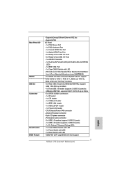
... audio connector - 3 x USB 2.0 headers (support 6 USB 2.0 ports) - 1 x USB 3.0 header (supports 2 USB 3.0 ports) - 1 x Dr. Debug (7-Segment Debug LED) - 1 x Clear CMOS Switch with LED - 1 x Power Switch with LED - 1 x Reset Switch with LED - 32Mb AMI UEFI Legal BIOS with LED - HD Audio Jack: Side Speaker/Rear Speaker...- 1 x eSATA3 Connector - 1 x RJ-45 LAN Port with LED (ACT/LINK LED and SPEED LED) - 1 x IEEE 1394 Port - 1 x Clear CMOS Switch with GUI support - Supports "Plug and Play" 7 Supports PXE I /O SATA3 USB 3.0 Connector Smart Switch BIOS Feature - CPU/Chassis/Power FAN connector ...
... audio connector - 3 x USB 2.0 headers (support 6 USB 2.0 ports) - 1 x USB 3.0 header (supports 2 USB 3.0 ports) - 1 x Dr. Debug (7-Segment Debug LED) - 1 x Clear CMOS Switch with LED - 1 x Power Switch with LED - 1 x Reset Switch with LED - 32Mb AMI UEFI Legal BIOS with LED - HD Audio Jack: Side Speaker/Rear Speaker...- 1 x eSATA3 Connector - 1 x RJ-45 LAN Port with LED (ACT/LINK LED and SPEED LED) - 1 x IEEE 1394 Port - 1 x Clear CMOS Switch with GUI support - Supports "Plug and Play" 7 Supports PXE I /O SATA3 USB 3.0 Connector Smart Switch BIOS Feature - CPU/Chassis/Power FAN connector ...

User Manual
Page 12
... Header (SPEAKER 1, White) 41 PCI Express 2.0 x1 Slot (PCIE1; White) 18 Power LED Header (PLED1) 39 PCI Slot (PCI1) 19 Clear CMOS Jumper (CLRCMOS1) 40 PCI Express 2.0 x16 Slot (PCIE2; White) 30 USB 2.0 Header (USB_10_11, Blue) 9 Chassis Fan Connector (CHA_FAN1) 31...: LINE IN Center: FRONT Bottom: MIC IN USB_12_13 HD_AUDIO1 PCIE1 AMD 970 Chipset PCIE2 AUDIO CODEC PCI1 PCIE3 CMOS BATTERY Super I/O 32Mb BIOS HDMI_SPDIF1 IR1 1 1 COM1 PCIE4 PCI2 PCIE5 USB_10_11 USB_8_9 1 1 970 Extreme4 SATA3 6Gb/s SATA3_4_5 USB_6_7 1 1 CIR1 SATA3_2_3 AMD SB950 Chipset SATA3_1 ...
... Header (SPEAKER 1, White) 41 PCI Express 2.0 x1 Slot (PCIE1; White) 18 Power LED Header (PLED1) 39 PCI Slot (PCI1) 19 Clear CMOS Jumper (CLRCMOS1) 40 PCI Express 2.0 x16 Slot (PCIE2; White) 30 USB 2.0 Header (USB_10_11, Blue) 9 Chassis Fan Connector (CHA_FAN1) 31...: LINE IN Center: FRONT Bottom: MIC IN USB_12_13 HD_AUDIO1 PCIE1 AMD 970 Chipset PCIE2 AUDIO CODEC PCI1 PCIE3 CMOS BATTERY Super I/O 32Mb BIOS HDMI_SPDIF1 IR1 1 1 COM1 PCIE4 PCI2 PCIE5 USB_10_11 USB_8_9 1 1 970 Extreme4 SATA3 6Gb/s SATA3_4_5 USB_6_7 1 1 CIR1 SATA3_2_3 AMD SB950 Chipset SATA3_1 ...
User Manual
Page 13
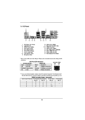
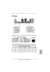
... Speaker (Lime) 9 Microphone (Pink) 10 11 *** 12 13 14 15 16 17 USB 3.0 Port (USB45) IEEE 1394 Port (IEEE 1394) eSATA3 Connector USB 2.0 Ports (USB01) Clear CMOS Switch (CLRCBTN) Optical SPDIF Out Port Coaxial SPDIF Out Port PS/2 Keyboard Port (Purple) * There are two LED next to the table below for connection...
... Speaker (Lime) 9 Microphone (Pink) 10 11 *** 12 13 14 15 16 17 USB 3.0 Port (USB45) IEEE 1394 Port (IEEE 1394) eSATA3 Connector USB 2.0 Ports (USB01) Clear CMOS Switch (CLRCBTN) Optical SPDIF Out Port Coaxial SPDIF Out Port PS/2 Keyboard Port (Purple) * There are two LED next to the table below for connection...

User Manual
Page 30
... reset the system parameters to short pin2 and pin3 on CLRCMOS1 for 5 seconds. Jumper Setting Clear CMOS Jumper (CLRCMOS1) (see p.12, No. 19) Default Clear CMOS Note: CLRCMOS1 allows you to clear the CMOS when you just f nish updating the BIOS, you must boot up the system f rst, and then shut it down ...before you update the BIOS. If no jumper cap is placed on pins, the jumper is "Short". The Clear CMOS Switch has the same function as system password, date, time, and system setup parameters. After waiting for 15 seconds, use a jumper cap to default...
... reset the system parameters to short pin2 and pin3 on CLRCMOS1 for 5 seconds. Jumper Setting Clear CMOS Jumper (CLRCMOS1) (see p.12, No. 19) Default Clear CMOS Note: CLRCMOS1 allows you to clear the CMOS when you just f nish updating the BIOS, you must boot up the system f rst, and then shut it down ...before you update the BIOS. If no jumper cap is placed on pins, the jumper is "Short". The Clear CMOS Switch has the same function as system password, date, time, and system setup parameters. After waiting for 15 seconds, use a jumper cap to default...
User Manual
Page 36
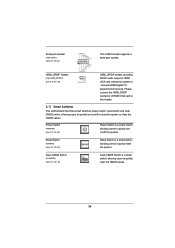
... this header. 2.11 Smart Switches This motherboard has three smart switches: power switch, reset switch and clear CMOS switch, allowing users to quickly turn on /off the system. Clear CMOS Switch (CLRCBTN) (see p.13 No. 14) Clear CMOS Switch is a smart switch, allowing users to quickly reset the system. HDMI_SPDIF Header (2-pin HDMI_SPDIF1)...(PWRBTN) (see p.12 No. 22) Reset Switch is a smart switch, allowing users to quickly turn on /off or reset the system or clear the CMOS values. Reset Switch (RSTBTN) (see p.12 No. 23) Power Switch is a smart switch, allowing users to quickly...
... this header. 2.11 Smart Switches This motherboard has three smart switches: power switch, reset switch and clear CMOS switch, allowing users to quickly turn on /off the system. Clear CMOS Switch (CLRCBTN) (see p.13 No. 14) Clear CMOS Switch is a smart switch, allowing users to quickly reset the system. HDMI_SPDIF Header (2-pin HDMI_SPDIF1)...(PWRBTN) (see p.12 No. 22) Reset Switch is a smart switch, allowing users to quickly turn on /off or reset the system or clear the CMOS values. Reset Switch (RSTBTN) (see p.12 No. 23) Power Switch is a smart switch, allowing users to quickly...

Quick Installation Guide
Page 2
...(HDMI_SPDIF1, White) 13 Southbridge Controller 34 PCI Express 2.0 x16 Slot (PCIE5; White) 18 Power LED Header (PLED1) 39 PCI Slot (PCI1) 19 Clear CMOS Jumper (CLRCMOS1) 40 PCI Express 2.0 x16 Slot (PCIE2; Blue) (CIR1) 8 2 x 240-pin DDR3 DIMM Slots 29 USB 2.0 Header (USB_8_9,... Panel Header (PANEL1, White) 42 Front Panel Audio Header 22 Reset Switch (RSTBTN) (HD_AUDIO1, White) English 2 ASRock 970 Extreme4 Motherboard Motherboard Layout Clr CMOS 1 234 24.4cm (9.6-in) 56 ATX12V1 PWR_FAN1 CPU_FAN2 CPU_FAN1 PS2 Mouse PS2 Coaxial Keyboard SPDIF Optical SPDIF RJ-45 LAN...
...(HDMI_SPDIF1, White) 13 Southbridge Controller 34 PCI Express 2.0 x16 Slot (PCIE5; White) 18 Power LED Header (PLED1) 39 PCI Slot (PCI1) 19 Clear CMOS Jumper (CLRCMOS1) 40 PCI Express 2.0 x16 Slot (PCIE2; Blue) (CIR1) 8 2 x 240-pin DDR3 DIMM Slots 29 USB 2.0 Header (USB_8_9,... Panel Header (PANEL1, White) 42 Front Panel Audio Header 22 Reset Switch (RSTBTN) (HD_AUDIO1, White) English 2 ASRock 970 Extreme4 Motherboard Motherboard Layout Clr CMOS 1 234 24.4cm (9.6-in) 56 ATX12V1 PWR_FAN1 CPU_FAN2 CPU_FAN1 PS2 Mouse PS2 Coaxial Keyboard SPDIF Optical SPDIF RJ-45 LAN...
Quick Installation Guide
Page 3
...Speaker (Lime) 9 Microphone (Pink) 10 11 *** 12 13 14 15 16 17 USB 3.0 Port (USB45) IEEE 1394 Port (IEEE 1394) eSATA3 Connector USB 2.0 Ports (USB01) Clear CMOS Switch (CLRCBTN) Optical SPDIF Out Port Coaxial SPDIF Out Port PS/2 Keyboard Port (Purple) * There are two LED next to the table below for connection... Jack". See the table below for Audio Output Connection Audio Output Channels Front Speaker Rear Speaker Central / Bass Side Speaker (No. 8) (No. 5) (No. 6) (No. 7) 2 V -- -- -- 4 V V -- -- 6 V V V -- 8 V V V V English 3 ASRock 970 Extreme4 Motherboard
...Speaker (Lime) 9 Microphone (Pink) 10 11 *** 12 13 14 15 16 17 USB 3.0 Port (USB45) IEEE 1394 Port (IEEE 1394) eSATA3 Connector USB 2.0 Ports (USB01) Clear CMOS Switch (CLRCBTN) Optical SPDIF Out Port Coaxial SPDIF Out Port PS/2 Keyboard Port (Purple) * There are two LED next to the table below for connection... Jack". See the table below for Audio Output Connection Audio Output Channels Front Speaker Rear Speaker Central / Bass Side Speaker (No. 8) (No. 5) (No. 6) (No. 7) 2 V -- -- -- 4 V V -- -- 6 V V V -- 8 V V V V English 3 ASRock 970 Extreme4 Motherboard
Quick Installation Guide
Page 7
... 1.0/2.0/3.0 up to -Use USB 3.0 Ports - 1 x eSATA3 Connector - 1 x RJ-45 LAN Port with LED (ACT/LINK LED and SPEED LED) - 1 x IEEE 1394 Port - 1 x Clear CMOS Switch with GUI support English 7 ASRock 970 Extreme4 Motherboard CPU/Chassis/Power FAN connector - 24 pin ATX power connector - 8 pin 12V power connector - Front panel audio connector - 3 x USB 2.0 headers (support 6 USB...
... 1.0/2.0/3.0 up to -Use USB 3.0 Ports - 1 x eSATA3 Connector - 1 x RJ-45 LAN Port with LED (ACT/LINK LED and SPEED LED) - 1 x IEEE 1394 Port - 1 x Clear CMOS Switch with GUI support English 7 ASRock 970 Extreme4 Motherboard CPU/Chassis/Power FAN connector - 24 pin ATX power connector - 8 pin 12V power connector - Front panel audio connector - 3 x USB 2.0 headers (support 6 USB...

Quick Installation Guide
Page 27
... off the computer and unplug the power cord from the power supply. To clear and reset the system parameters to clear the data in CMOS. English 27 ASRock 970 Extreme4 Motherboard If you update the BIOS. The Clear CMOS Switch has the same function as the Clear CMOS jumper. 2.9 Jumpers Setup The illustration shows how jumpers are "Short" when jumper...
... off the computer and unplug the power cord from the power supply. To clear and reset the system parameters to clear the data in CMOS. English 27 ASRock 970 Extreme4 Motherboard If you update the BIOS. The Clear CMOS Switch has the same function as the Clear CMOS jumper. 2.9 Jumpers Setup The illustration shows how jumpers are "Short" when jumper...

Quick Installation Guide
Page 34
... is a smart switch, allowing users to quickly turn on /off or reset the system or clear the CMOS values. Clear CMOS Switch (CLRCBTN) (see p.2 No. 22) Reset Switch is a smart switch, allowing users to quickly clear the CMOS values English 34 ASRock 970 Extreme4 Motherboard 2.11 Smart Switches This motherboard has three smart switches: power switch, reset switch and...
... is a smart switch, allowing users to quickly turn on /off or reset the system or clear the CMOS values. Clear CMOS Switch (CLRCBTN) (see p.2 No. 22) Reset Switch is a smart switch, allowing users to quickly clear the CMOS values English 34 ASRock 970 Extreme4 Motherboard 2.11 Smart Switches This motherboard has three smart switches: power switch, reset switch and...
Quick Installation Guide
Page 203
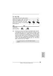
2.8 그림은 3 1-2 쇼트 오픈 점퍼 CMOS 초기화 (CLRCMOS1, 3 2 19 세팅 CMOS 삭제 참고 : CLRCMOS1 CMOS 15 CLRCMOS1 의 핀 2 와 핀 3 을 5 BIOS CMOS BIOS CMOS CMOS CMOS 1394 GUID, MAC Clear CMOS Switch는 Clear CMOS 한국어 203 ASRock 970 Extreme4 Motherboard
2.8 그림은 3 1-2 쇼트 오픈 점퍼 CMOS 초기화 (CLRCMOS1, 3 2 19 세팅 CMOS 삭제 참고 : CLRCMOS1 CMOS 15 CLRCMOS1 의 핀 2 와 핀 3 을 5 BIOS CMOS BIOS CMOS CMOS CMOS 1394 GUID, MAC Clear CMOS Switch는 Clear CMOS 한국어 203 ASRock 970 Extreme4 Motherboard

Quick Installation Guide
Page 274
2.8 3 針 1 和針腳 2 短接 開路 CMOS (CLRCMOS1, 3 2 頁第 19 項 ) 設定 默認設置 清除 CMOS 註: C L R C M O S1 C M O S 15 CLRCMOS1 的 pin2 及 pin3 短路 5 BIOS CMOS BIOS CMOS CMOS C M O S 1394 GUID 及 MAC Clear CMOS Clear CMOS 繁體中文 274 ASRock 970 Extreme4 Motherboard
2.8 3 針 1 和針腳 2 短接 開路 CMOS (CLRCMOS1, 3 2 頁第 19 項 ) 設定 默認設置 清除 CMOS 註: C L R C M O S1 C M O S 15 CLRCMOS1 的 pin2 及 pin3 短路 5 BIOS CMOS BIOS CMOS CMOS C M O S 1394 GUID 及 MAC Clear CMOS Clear CMOS 繁體中文 274 ASRock 970 Extreme4 Motherboard

