User Manual
Page 3
...Expansion Slots (PCI and PCI Express Slots 19 2.5 SLITM Operation Guide 20 2.6 CrossFireXTM, 3-Way CrossFireXTM and Quad CrossFireXTM Operation Guide 23 2.7 Surround Display Information 28 2.8 ASRock Smart Remote Installation Guide 29 2.9 Jumpers Setup 30 2.10 Onboard Headers and Connectors 31 2.11 Smart Switches 36 2.12 Dr. Debug 37 2.13 Serial ATA3...; 7 / 7 64-bit / VistaTM / VistaTM 64-bit Without RAID Functions 47 2.19 Untied Overclocking Technology 47 3 Introduction 5 1.1 Package Contents 5 1.2 Specif cations 6 1.3 Motherboard Layout 12 1.4 I/O Panel 13 2. Contents 1.
...Expansion Slots (PCI and PCI Express Slots 19 2.5 SLITM Operation Guide 20 2.6 CrossFireXTM, 3-Way CrossFireXTM and Quad CrossFireXTM Operation Guide 23 2.7 Surround Display Information 28 2.8 ASRock Smart Remote Installation Guide 29 2.9 Jumpers Setup 30 2.10 Onboard Headers and Connectors 31 2.11 Smart Switches 36 2.12 Dr. Debug 37 2.13 Serial ATA3...; 7 / 7 64-bit / VistaTM / VistaTM 64-bit Without RAID Functions 47 2.19 Untied Overclocking Technology 47 3 Introduction 5 1.1 Package Contents 5 1.2 Specif cations 6 1.3 Motherboard Layout 12 1.4 I/O Panel 13 2. Contents 1.

User Manual
Page 5
... / VistaTM 64 bit, it is recommended to set the BIOS option in , 30.5 cm x 24.4 cm) ASRock 970 Extreme4 Quick Installation Guide ASRock 970 Extreme4 Support CD 1 x ASRock SLI_Bridge_2S Card 4 x Serial ATA (SATA) Data Cables (Optional) 1 x 3.5mm Audio Cable (Optional) 1 x I/O Panel Shield ASRock Reminds You... Chapter 3 and 4 contain the conf guration guide to BIOS setup and information of the...
... / VistaTM 64 bit, it is recommended to set the BIOS option in , 30.5 cm x 24.4 cm) ASRock 970 Extreme4 Quick Installation Guide ASRock 970 Extreme4 Support CD 1 x ASRock SLI_Bridge_2S Card 4 x Serial ATA (SATA) Data Cables (Optional) 1 x 3.5mm Audio Cable (Optional) 1 x I/O Panel Shield ASRock Reminds You... Chapter 3 and 4 contain the conf guration guide to BIOS setup and information of the...

User Manual
Page 7
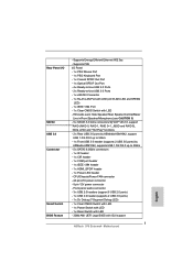
CPU/Chassis/Power FAN connector - 24 pin ATX power connector - 8 pin 12V power connector - Supports "Plug and Play" 7 Front panel audio connector - 3 x USB 2.0 headers (support 6 USB 2.0 ports) - 1 x USB 3.0 header (supports 2 USB 3.0 ports) - 1 x Dr. Debug (7-Segment Debug...LINK LED and SPEED LED) - 1 x IEEE 1394 Port - 1 x Clear CMOS Switch with GUI support - Supports PXE I /O SATA3 USB 3.0 Connector Smart Switch BIOS Feature - Rear Panel I /O Panel - 1 x PS/2 Mouse Port - 1 x PS/2 Keyboard Port - 1 x Coaxial SPDIF Out Port - 1 x Optical SPDIF Out Port - 4 x Ready-to-Use USB 2.0 ...
CPU/Chassis/Power FAN connector - 24 pin ATX power connector - 8 pin 12V power connector - Supports "Plug and Play" 7 Front panel audio connector - 3 x USB 2.0 headers (support 6 USB 2.0 ports) - 1 x USB 3.0 header (supports 2 USB 3.0 ports) - 1 x Dr. Debug (7-Segment Debug...LINK LED and SPEED LED) - 1 x IEEE 1394 Port - 1 x Clear CMOS Switch with GUI support - Supports PXE I /O SATA3 USB 3.0 Connector Smart Switch BIOS Feature - Rear Panel I /O Panel - 1 x PS/2 Mouse Port - 1 x PS/2 Keyboard Port - 1 x Coaxial SPDIF Out Port - 1 x Optical SPDIF Out Port - 4 x Ready-to-Use USB 2.0 ...

User Manual
Page 12
... 32Mb BIOS HDMI_SPDIF1 IR1 1 1 COM1 PCIE4 PCI2 PCIE5 USB_10_11 USB_8_9 1 1 970 Extreme4 SATA3 6Gb/s SATA3_4_5 USB_6_7 1 1 CIR1 SATA3_2_3 AMD SB950 Chipset SATA3_1 X FAST USB CHA_FAN3 Front USB 3.0 1394a PLED1 FRONT_1394 1 PANEL 1 PLED PWRBTN 1 CHA_FAN2 PWRBTN1 RSTBTN1 1 HDLED RESET Dr. Debug CLRCMOS1 1 ...15 16 17 18 19 1 ATX 12V Power Connector (ATX12V1) 23 Power Switch (PWRBTN) 2 Power Fan Connector (PWR_FAN1) 24 Front Panel IEEE 1394 Header 3 CPU Fan Connector (CPU_FAN2) (FRONT_1394, White) 4 CPU Fan Connector (CPU_FAN1) 25 Chassis Fan Connector (CHA_FAN2) ...
... 32Mb BIOS HDMI_SPDIF1 IR1 1 1 COM1 PCIE4 PCI2 PCIE5 USB_10_11 USB_8_9 1 1 970 Extreme4 SATA3 6Gb/s SATA3_4_5 USB_6_7 1 1 CIR1 SATA3_2_3 AMD SB950 Chipset SATA3_1 X FAST USB CHA_FAN3 Front USB 3.0 1394a PLED1 FRONT_1394 1 PANEL 1 PLED PWRBTN 1 CHA_FAN2 PWRBTN1 RSTBTN1 1 HDLED RESET Dr. Debug CLRCMOS1 1 ...15 16 17 18 19 1 ATX 12V Power Connector (ATX12V1) 23 Power Switch (PWRBTN) 2 Power Fan Connector (PWR_FAN1) 24 Front Panel IEEE 1394 Header 3 CPU Fan Connector (CPU_FAN2) (FRONT_1394, White) 4 CPU Fan Connector (CPU_FAN1) 25 Chassis Fan Connector (CHA_FAN2) ...
User Manual
Page 13
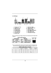
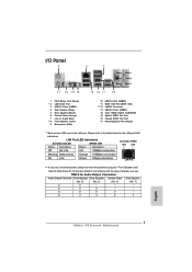
... Central / Bass Side Speaker (No. 8) (No. 5) (No. 6) (No. 7) 2 V -- -- -- 4 V V -- -- 6 V V V -- 8 V V V V 13 Please refer to the LAN port. See the table below for the LAN port LED indications. 1.4 I/O Panel 1 2 3 4 7 5 8 6 9 17 16 15 14 13 12 11 10 1 PS/2 Mouse Port (Green) * 2 LAN RJ-45 Port 3 USB 2.0 Ports (USB23) 4 Side Speaker (Gray) 5 Rear Speaker (Black...
... Central / Bass Side Speaker (No. 8) (No. 5) (No. 6) (No. 7) 2 V -- -- -- 4 V V -- -- 6 V V V -- 8 V V V V 13 Please refer to the LAN port. See the table below for the LAN port LED indications. 1.4 I/O Panel 1 2 3 4 7 5 8 6 9 17 16 15 14 13 12 11 10 1 PS/2 Mouse Port (Green) * 2 LAN RJ-45 Port 3 USB 2.0 Ports (USB23) 4 Side Speaker (Gray) 5 Rear Speaker (Black...
User Manual
Page 14
To enable Multi-Streaming function, you will f nd "Mixer" tool on your computer, you need to connect a front panel audio cable to use Rear Speaker, Central/Bass, and Front Speaker, or select "Realtek HDA Audio 2nd output" to the front panel audio header. Please select "Mixer ToolBox" , click "Enable playback multi-streaming", and click "ok". After restarting your system. Choose "2CH", "4CH", "6CH", or "8CH" and then you are allowed to select "Realtek HDA Primary output" to use front panel audio. *** eSATA3 connector supports SATA Gen3 in cable 1M. 14
To enable Multi-Streaming function, you will f nd "Mixer" tool on your computer, you need to connect a front panel audio cable to use Rear Speaker, Central/Bass, and Front Speaker, or select "Realtek HDA Audio 2nd output" to the front panel audio header. Please select "Mixer ToolBox" , click "Enable playback multi-streaming", and click "ok". After restarting your system. Choose "2CH", "4CH", "6CH", or "8CH" and then you are allowed to select "Realtek HDA Primary output" to use front panel audio. *** eSATA3 connector supports SATA Gen3 in cable 1M. 14

User Manual
Page 22
... and to the owners' benef t, without intent to infringe. 22 C. In Set PhysX GPU acceleration item, please select Enabled. Reboot your Windows taskbar. Select Control Panel tab. And click Apply. For Windows® VistaTM / VistaTM 64-bit / 7 / 7 64-bit OS: A. B. D. Select NVIDIA Control...
... and to the owners' benef t, without intent to infringe. 22 C. In Set PhysX GPU acceleration item, please select Enabled. Reboot your Windows taskbar. Select Control Panel tab. And click Apply. For Windows® VistaTM / VistaTM 64-bit / 7 / 7 64-bit OS: A. B. D. Select NVIDIA Control...
User Manual
Page 29
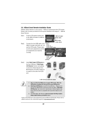
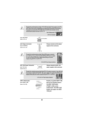
... Remote is only used for ASRock motherboard with most of ASRock Smart Remote. Find the CIR header located next to the USB 2.0 header on the rear panel. Please make GND DUMMY sure the wire assignments and the pin assignments are matched correctly. Multi-Angle CIR Receiver is used for...rear USB bracket to connect it to below , pin 1-5) P+ (4-pin, white) and the CIR header. Please refer to install it on ASRock USB 2.0 header (9-pin, blue) motherboard. If Multi-Angle CIR Receiver cannot successfully receive the infrared signals from MCE Remote Controller, please try to...
... Remote is only used for ASRock motherboard with most of ASRock Smart Remote. Find the CIR header located next to the USB 2.0 header on the rear panel. Please make GND DUMMY sure the wire assignments and the pin assignments are matched correctly. Multi-Angle CIR Receiver is used for...rear USB bracket to connect it to below , pin 1-5) P+ (4-pin, white) and the CIR header. Please refer to install it on ASRock USB 2.0 header (9-pin, blue) motherboard. If Multi-Angle CIR Receiver cannot successfully receive the infrared signals from MCE Remote Controller, please try to...
User Manual
Page 31
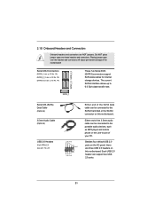
... SATA data cables for internal storage devices. Each USB 2.0 header can be connected to 6.0 Gb/s data transfer rate. Besides four default USB 2.0 ports on the I/O panel, there are NOT jumpers. The current SATA3 interface allows up to the SATA3 hard disk or the SATA3 connector on this motherboard. Placing jumper caps...
... SATA data cables for internal storage devices. Each USB 2.0 header can be connected to 6.0 Gb/s data transfer rate. Besides four default USB 2.0 ports on the I/O panel, there are NOT jumpers. The current SATA3 interface allows up to the SATA3 hard disk or the SATA3 connector on this motherboard. Placing jumper caps...
User Manual
Page 32
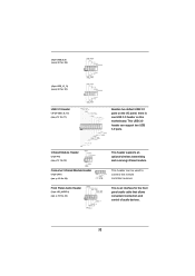
... p.12 No. 32) Consumer Infrared Module Header (4-pin CIR1) (see p.12 No. 28) Front Panel Audio Header (9-pin HD_AUDIO1) (see p.12 No. 11) Besides two default USB 3.0 ports on the I/O panel, there is an interface for the front panel audio cable that allows convenient connection and control of audio devices. 32 (9-pin USB_8_9...
... p.12 No. 32) Consumer Infrared Module Header (4-pin CIR1) (see p.12 No. 28) Front Panel Audio Header (9-pin HD_AUDIO1) (see p.12 No. 11) Besides two default USB 3.0 ports on the I/O panel, there is an interface for the front panel audio cable that allows convenient connection and control of audio devices. 32 (9-pin USB_8_9...
User Manual
Page 33
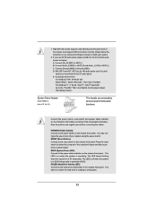
...FrontMic". Press the reset switch to restart the computer if the computer freezes and fails to MIC2_L. Please follow the instruction in the Realtek Control panel. B. C. D. You don't need to function correctly. To activate the front mic. Connect the power switch, reset switch and system status ...to the pin assignments below : A. Connect Audio_R (RIN) to OUT2_R and Audio_L (LIN) to turn off when the system is on the chassis front panel. Note the positive and negative pins before connecting the cables. E. For Windows® XP / XP 64-bit OS: Select "Mixer". 1. PWRBTN (...
...FrontMic". Press the reset switch to restart the computer if the computer freezes and fails to MIC2_L. Please follow the instruction in the Realtek Control panel. B. C. D. You don't need to function correctly. To activate the front mic. Connect the power switch, reset switch and system status ...to the pin assignments below : A. Connect Audio_R (RIN) to OUT2_R and Audio_L (LIN) to turn off when the system is on the chassis front panel. Note the positive and negative pins before connecting the cables. E. For Windows® XP / XP 64-bit OS: Select "Mixer". 1. PWRBTN (...

User Manual
Page 34
...Please connect the fan cables to the fan connectors and match the black wire to the ground pin. The front panel design may differ by chassis. When connecting your chassis front panel module to indicate system power status. The LED is on when the system is off ). The LED keeps ...or S5 state (power off in S1 state. The LED is operating. Please connect the chassis power LED to this header to this header. A front panel module mainly consists of power switch, reset switch, power LED, hard drive activity LED, speaker and etc. Chassis and Power Fan Connectors (4-pin CHA_FAN1) ...
...Please connect the fan cables to the fan connectors and match the black wire to the ground pin. The front panel design may differ by chassis. When connecting your chassis front panel module to indicate system power status. The LED is on when the system is off ). The LED keeps ...or S5 state (power off in S1 state. The LED is operating. Please connect the chassis power LED to this header to this header. A front panel module mainly consists of power switch, reset switch, power LED, hard drive activity LED, speaker and etc. Chassis and Power Fan Connectors (4-pin CHA_FAN1) ...
User Manual
Page 35
...-pin ATXPWR1) (see p.12 No. 24) Besides one default IEEE 1394 port on this motherboard, please connect it to the CPU fan connector on the I/O panel, there is one IEEE 1394 port. 35 Though this motherboard provides 4-Pin CPU fan (Quiet Fan) support, the 3-Pin CPU fan still can still work...
...-pin ATXPWR1) (see p.12 No. 24) Besides one default IEEE 1394 port on this motherboard, please connect it to the CPU fan connector on the I/O panel, there is one IEEE 1394 port. 35 Though this motherboard provides 4-Pin CPU fan (Quiet Fan) support, the 3-Pin CPU fan still can still work...

User Manual
Page 57
... Deep Sx, please disable On/Off Play f rst. Good Night LED This allows you to turn off Power LED, Lan LED at power on. Front Panel Select [Auto] or [Disabled] for the onboard HD Audio feature. The default value is plugged. When On/Off Play is enabled, Deep Sx will be... to enable or disable On/Off Play Technology. 3.4.3 South Bridge Configuration Onboard HD Audio Select [Auto], [Enabled] or [Disabled] for the onboard HD Audio Front Panel.
... Deep Sx, please disable On/Off Play f rst. Good Night LED This allows you to turn off Power LED, Lan LED at power on. Front Panel Select [Auto] or [Disabled] for the onboard HD Audio feature. The default value is plugged. When On/Off Play is enabled, Deep Sx will be... to enable or disable On/Off Play Technology. 3.4.3 South Bridge Configuration Onboard HD Audio Select [Auto], [Enabled] or [Disabled] for the onboard HD Audio Front Panel.

Quick Installation Guide
Page 2
White) 21 System Panel Header (PANEL1, White) 42 Front Panel Audio Header 22 Reset Switch (RSTBTN) (HD_AUDIO1, White) English 2 ASRock 970 Extreme4 Motherboard Motherboard Layout Clr CMOS 1 234 24.4cm (9.6-in) 56 ATX12V1 PWR_FAN1 CPU_FAN2...I/O 32Mb BIOS HDMI_SPDIF1 IR1 1 1 COM1 PCIE4 PCI2 PCIE5 USB_10_11 USB_8_9 1 1 970 Extreme4 SATA3 6Gb/s SATA3_4_5 USB_6_7 1 1 CIR1 SATA3_2_3 AMD SB950 Chipset SATA3_1 X FAST USB CHA_FAN3 Front USB 3.0 1394a PLED1 FRONT_1394 1 PANEL 1 PLED PWRBTN 1 CHA_FAN2 PWRBTN1 RSTBTN1 1 HDLED RESET Dr. Debug CLRCMOS1 1 SPEAKER1...
White) 21 System Panel Header (PANEL1, White) 42 Front Panel Audio Header 22 Reset Switch (RSTBTN) (HD_AUDIO1, White) English 2 ASRock 970 Extreme4 Motherboard Motherboard Layout Clr CMOS 1 234 24.4cm (9.6-in) 56 ATX12V1 PWR_FAN1 CPU_FAN2...I/O 32Mb BIOS HDMI_SPDIF1 IR1 1 1 COM1 PCIE4 PCI2 PCIE5 USB_10_11 USB_8_9 1 1 970 Extreme4 SATA3 6Gb/s SATA3_4_5 USB_6_7 1 1 CIR1 SATA3_2_3 AMD SB950 Chipset SATA3_1 X FAST USB CHA_FAN3 Front USB 3.0 1394a PLED1 FRONT_1394 1 PANEL 1 PLED PWRBTN 1 CHA_FAN2 PWRBTN1 RSTBTN1 1 HDLED RESET Dr. Debug CLRCMOS1 1 SPEAKER1...
Quick Installation Guide
Page 3
Please refer to the LAN port. TABLE for connection details in accordance with the type of speaker you use . I/O Panel 1 2 3 4 7 5 8 6 9 17 16 15 14 13 12 11 10 1 PS/2 Mouse Port (Green) * 2 LAN RJ-45 Port 3 USB 2.0 Ports...Speaker Rear Speaker Central / Bass Side Speaker (No. 8) (No. 5) (No. 6) (No. 7) 2 V -- -- -- 4 V V -- -- 6 V V V -- 8 V V V V English 3 ASRock 970 Extreme4 Motherboard LAN Port LED Indications Activity/Link LED SPEED LED Status Description Status Description ACT/LINK SPEED LED LED Off No Link Off 10Mbps connection...
Please refer to the LAN port. TABLE for connection details in accordance with the type of speaker you use . I/O Panel 1 2 3 4 7 5 8 6 9 17 16 15 14 13 12 11 10 1 PS/2 Mouse Port (Green) * 2 LAN RJ-45 Port 3 USB 2.0 Ports...Speaker Rear Speaker Central / Bass Side Speaker (No. 8) (No. 5) (No. 6) (No. 7) 2 V -- -- -- 4 V V -- -- 6 V V V -- 8 V V V V English 3 ASRock 970 Extreme4 Motherboard LAN Port LED Indications Activity/Link LED SPEED LED Status Description Status Description ACT/LINK SPEED LED LED Off No Link Off 10Mbps connection...
Quick Installation Guide
Page 4
English 4 ASRock 970 Extreme4 Motherboard After restarting your computer, you are allowed to select "Realtek HDA Primary output" to use Rear Speaker, Central/Bass, and Front Speaker, or select "Realtek HDA Audio 2nd output" to the front panel audio header. Please select "Mixer ToolBox" , click "Enable ...playback multi-streaming", and click "ok". To enable Multi-Streaming function, you need to connect a front panel audio cable to use front panel audio. *** eSATA3 connector supports SATA Gen3 in cable 1M. Choose "2CH", "4CH", "6CH", or "8CH" and then you...
English 4 ASRock 970 Extreme4 Motherboard After restarting your computer, you are allowed to select "Realtek HDA Primary output" to use Rear Speaker, Central/Bass, and Front Speaker, or select "Realtek HDA Audio 2nd output" to the front panel audio header. Please select "Mixer ToolBox" , click "Enable ...playback multi-streaming", and click "ok". To enable Multi-Streaming function, you need to connect a front panel audio cable to use front panel audio. *** eSATA3 connector supports SATA Gen3 in cable 1M. Choose "2CH", "4CH", "6CH", or "8CH" and then you...
Quick Installation Guide
Page 5
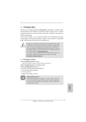
... about the model you require technical support related to the "User Manual" in , 30.5 cm x 24.4 cm) ASRock 970 Extreme4 Quick Installation Guide ASRock 970 Extreme4 Support CD 4 x Serial ATA (SATA) Data Cables (Optional) 1 x 3.5mm Audio Cable (Optional) 1 x I/O Panel Shield 1 x ASRock SLI_Bridge_2S Card ASRock Reminds You... You may find the latest VGA cards and CPU support lists on...
... about the model you require technical support related to the "User Manual" in , 30.5 cm x 24.4 cm) ASRock 970 Extreme4 Quick Installation Guide ASRock 970 Extreme4 Support CD 4 x Serial ATA (SATA) Data Cables (Optional) 1 x 3.5mm Audio Cable (Optional) 1 x I/O Panel Shield 1 x ASRock SLI_Bridge_2S Card ASRock Reminds You... You may find the latest VGA cards and CPU support lists on...
Quick Installation Guide
Page 7
... SATA3 6.0Gb/s connectors - 1 x IR header - 1 x CIR header - 1 x COM port header - 1 x IEEE 1394 header - 1 x HDMI_SPDIF header - 1 x Power LED header - Front panel audio connector - 3 x USB 2.0 headers (support 6 USB 2.0 ports) - 1 x USB 3.0 header (supports 2 USB 3.0 ports) - 1 x Dr. Debug (7-Segment Debug LED) Smart Switch - ... LED and SPEED LED) - 1 x IEEE 1394 Port - 1 x Clear CMOS Switch with GUI support English 7 ASRock 970 Extreme4 Motherboard Supports Energy Efficient Ethernet 802.3az - CPU/Chassis/Power FAN connector - 24 pin ATX power connector - 8 pin ...
... SATA3 6.0Gb/s connectors - 1 x IR header - 1 x CIR header - 1 x COM port header - 1 x IEEE 1394 header - 1 x HDMI_SPDIF header - 1 x Power LED header - Front panel audio connector - 3 x USB 2.0 headers (support 6 USB 2.0 ports) - 1 x USB 3.0 header (supports 2 USB 3.0 ports) - 1 x Dr. Debug (7-Segment Debug LED) Smart Switch - ... LED and SPEED LED) - 1 x IEEE 1394 Port - 1 x Clear CMOS Switch with GUI support English 7 ASRock 970 Extreme4 Motherboard Supports Energy Efficient Ethernet 802.3az - CPU/Chassis/Power FAN connector - 24 pin ATX power connector - 8 pin ...
Quick Installation Guide
Page 19
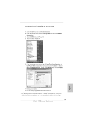
... Panel tab. Click the Start icon on your system. E. B. G.You can freely enjoy the benefit of SLITM feature. * SLITM appearing here is a registered trademark of NVIDIA® Technologies Inc., and is used only for identification or explanation and to the owners' benefit, without intent to infringe. 19 ASRock 970 Extreme4... Motherboard English Select NVIDIA Control Panel tab. C.
... Panel tab. Click the Start icon on your system. E. B. G.You can freely enjoy the benefit of SLITM feature. * SLITM appearing here is a registered trademark of NVIDIA® Technologies Inc., and is used only for identification or explanation and to the owners' benefit, without intent to infringe. 19 ASRock 970 Extreme4... Motherboard English Select NVIDIA Control Panel tab. C.

