

User Manual
Page 6
V4 + 1 Power Phase Design - Northbridge: AMD 970 - Support DDR3 2100(OC)/1866(OC)/1800(OC)/1600(OC)/ 1333/1066/800 non-ECC, un-buffered memory (see CAUTION 2) - Supports Wake-On-LAN - Supports ...
V4 + 1 Power Phase Design - Northbridge: AMD 970 - Support DDR3 2100(OC)/1866(OC)/1800(OC)/1600(OC)/ 1333/1066/800 non-ECC, un-buffered memory (see CAUTION 2) - Supports Wake-On-LAN - Supports ...
User Manual
Page 7
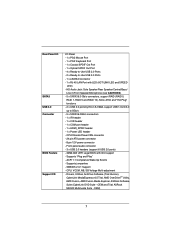
...- 24 pin ATX power connector - 8 pin 12V power connector - ACPI 1.1 Compliance Wake Up Events - SMBIOS 2.3.1 Support - Drivers, Utilities, AntiVirus Software (Trial Version), CyberLink MediaEspresso 6.5 Trial, AMD OverDriveTM Utility, AMD Fusion, AMD Fusion Media Explorer, ASRock Software Suite (CyberLink...1.0/2.0/3.0 up to -Use USB 3.0 Ports - 1 x eSATA3 Connector - 1 x RJ-45 LAN Port with GUI support - Supports "Plug and Play" - ASRock MAGIX Multimedia Suite - Rear Panel I/O SATA3 USB 3.0 Connector BIOS Feature Support CD I/O Panel - 1 x PS/2 Mouse Port - 1 x PS/2 Keyboard ...
...- 24 pin ATX power connector - 8 pin 12V power connector - ACPI 1.1 Compliance Wake Up Events - SMBIOS 2.3.1 Support - Drivers, Utilities, AntiVirus Software (Trial Version), CyberLink MediaEspresso 6.5 Trial, AMD OverDriveTM Utility, AMD Fusion, AMD Fusion Media Explorer, ASRock Software Suite (CyberLink...1.0/2.0/3.0 up to -Use USB 3.0 Ports - 1 x eSATA3 Connector - 1 x RJ-45 LAN Port with GUI support - Supports "Plug and Play" - ASRock MAGIX Multimedia Suite - Rear Panel I/O SATA3 USB 3.0 Connector BIOS Feature Support CD I/O Panel - 1 x PS/2 Mouse Port - 1 x PS/2 Keyboard ...

User Manual
Page 8
...Hardware - CPU Temperature Sensing Monitor - ErP/EuP Ready (ErP/EuP ready power supply is required) (see CAUTION 14) - We are not responsible for possible damage caused by overclocking. 8 ASRock Instant Boot - CPU Frequency Stepless Control (see CAUTION 16) * For ...Overclocking Technology, or using the third-party overclocking tools. Voltage Monitoring: +12V, +5V, +3.3V, Vcore OS - ASRock Instant Flash (see CAUTION 10) - ASRock SmartView (see CAUTION 8) - ASRock XFast LAN (see CAUTION 7) - Microsoft® Windows® 7 / 7 64-bit / VistaTM / VistaTM 64-...
...Hardware - CPU Temperature Sensing Monitor - ErP/EuP Ready (ErP/EuP ready power supply is required) (see CAUTION 14) - We are not responsible for possible damage caused by overclocking. 8 ASRock Instant Boot - CPU Frequency Stepless Control (see CAUTION 16) * For ...Overclocking Technology, or using the third-party overclocking tools. Voltage Monitoring: +12V, +5V, +3.3V, Vcore OS - ASRock Instant Flash (see CAUTION 10) - ASRock SmartView (see CAUTION 8) - ASRock XFast LAN (see CAUTION 7) - Microsoft® Windows® 7 / 7 64-bit / VistaTM / VistaTM 64-...
User Manual
Page 10
...-time newsfeed into Standby mode (S1), Suspend to RAM (S3), hibernation mode (S4) or power off (or in touch with the ASRock SmartView utility that the USB flash drive or hard drive must use ASRock SmartView feature, please make sure your OS version is Windows® 7 / 7 64 bit ...video and download files simultaneously. This convenient BIOS update tool allows you can update your Apple devices, such as iPhone/iPod/iPad Touch, ASRock has prepared a wonderful solution for you are exclusively equipped with friends on the property of charging your BIOS only in a few clicks...
...-time newsfeed into Standby mode (S1), Suspend to RAM (S3), hibernation mode (S4) or power off (or in touch with the ASRock SmartView utility that the USB flash drive or hard drive must use ASRock SmartView feature, please make sure your OS version is Windows® 7 / 7 64 bit ...video and download files simultaneously. This convenient BIOS update tool allows you can update your Apple devices, such as iPhone/iPod/iPad Touch, ASRock has prepared a wonderful solution for you are exclusively equipped with friends on the property of charging your BIOS only in a few clicks...

User Manual
Page 11
... please check if the CPU fan on the motherboard functions properly and unplug the power cord, then plug it is detected, the system will automatically shutdown. To meet the standard of 5v standby power efficiency is higher than the recommended CPU bus frequencies may cause the ...instability of the completed system shall be under 100 mA current consumption. According to perform over-clocking. For EuP ready power supply selection, we recommend you install the PC system. 16. According to spray thermal grease between the CPU and the heatsink when you...
... please check if the CPU fan on the motherboard functions properly and unplug the power cord, then plug it is detected, the system will automatically shutdown. To meet the standard of 5v standby power efficiency is higher than the recommended CPU bus frequencies may cause the ...instability of the completed system shall be under 100 mA current consumption. According to perform over-clocking. For EuP ready power supply selection, we recommend you install the PC system. 16. According to spray thermal grease between the CPU and the heatsink when you...

User Manual
Page 15
... not over-tighten the screws! To avoid damaging the motherboard components due to static electricity, NEVER place your chassis to ensure that the power is switched off or the power cord is an ATX form factor (12.0-in x 8.6-in the bag that comes with the component. 5. Before you uninstall any component, ensure... that the motherboard fits into the screw holes to secure the motherboard to the motherboard, peripherals, and/or components. 1. Unplug the power cord from the power supply. Whenever you install or remove any component, place it . 2.
... not over-tighten the screws! To avoid damaging the motherboard components due to static electricity, NEVER place your chassis to ensure that the power is switched off or the power cord is an ATX form factor (12.0-in x 8.6-in the bag that comes with the component. 5. Before you uninstall any component, ensure... that the motherboard fits into the screw holes to secure the motherboard to the motherboard, peripherals, and/or components. 1. Unplug the power cord from the power supply. Whenever you install or remove any component, place it . 2.

User Manual
Page 18
It will cause permanent damage to disconnect power supply before adding or removing DIMMs or the system components. Installing a DIMM Please make sure to the motherboard and the DIMM if you force the ...
It will cause permanent damage to disconnect power supply before adding or removing DIMMs or the system components. Installing a DIMM Please make sure to the motherboard and the DIMM if you force the ...

User Manual
Page 19
... slot will work at x16 bandwidth while PCIE4 slot will work at x4 bandwidth. 3. Remove the bracket facing the slot that the power supply is switched off or the power cord is used to install a PCI Express x16 graphics card on the slot. PCIE2 (PCIE x16 slot; Step 4. PCI Slots: PCI slots...
... slot will work at x16 bandwidth while PCIE4 slot will work at x4 bandwidth. 3. Remove the bracket facing the slot that the power supply is switched off or the power cord is used to install a PCI Express x16 graphics card on the slot. PCIE2 (PCIE x16 slot; Step 4. PCI Slots: PCI slots...

User Manual
Page 22
... and Setup Step 1. Remove the AMDTM driver if you will find "ATI Catalyst Control Center" on your computer and boot into OS. Step 3. Step 5. Power on your sys- For Windows® XP OS: A. Please check Microsoft website for AMDTM driver updates. Install the VGA card drivers to uninstall any VGA...
... and Setup Step 1. Remove the AMDTM driver if you will find "ATI Catalyst Control Center" on your computer and boot into OS. Step 3. Step 5. Power on your sys- For Windows® XP OS: A. Please check Microsoft website for AMDTM driver updates. Install the VGA card drivers to uninstall any VGA...

User Manual
Page 25
... then shut it down before you do not clear the CMOS right after you to default setup, please turn off the computer and unplug the power cord from the power supply. The illustration shows a 3-pin jumper whose pin1 and pin2 are setup.
... then shut it down before you do not clear the CMOS right after you to default setup, please turn off the computer and unplug the power cord from the power supply. The illustration shows a 3-pin jumper whose pin1 and pin2 are setup.

User Manual
Page 27
... manual to function correctly. RESET (Reset Switch): Connect to the reset switch on the chassis must support HDA to install your system using the power switch. Connect Mic_IN (MIC) to Ground (GND). To activate the front mic. Press the reset switch to restart the computer if the computer.... C. MIC_RET and OUT_RET are for HD audio panel only. For Windows® XP / XP 64-bit OS: Select "Mixer". PWRBTN (Power Switch): Connect to the power switch on the chassis to this header according to connect the remote controller receiver. Connect Audio_R (RIN) to OUT2_R and Audio_L (LIN) to...
... manual to function correctly. RESET (Reset Switch): Connect to the reset switch on the chassis must support HDA to install your system using the power switch. Connect Mic_IN (MIC) to Ground (GND). To activate the front mic. Press the reset switch to restart the computer if the computer.... C. MIC_RET and OUT_RET are for HD audio panel only. For Windows® XP / XP 64-bit OS: Select "Mixer". PWRBTN (Power Switch): Connect to the power switch on the chassis to this header according to connect the remote controller receiver. Connect Audio_R (RIN) to OUT2_R and Audio_L (LIN) to...

User Manual
Page 28
...The LED keeps blinking when the sys-tem is operating. Chassis Speaker Header (4-pin SPEAKER 1) (see p.12 No. 24) Power LED Header (3-pin PLED1) (see p.12 No. 22) 1 PLEDPLED+ PLED+ Chassis and Power Fan Connectors (4-pin CHA_FAN1) (see p.12 No. 12) GND +12V CHA_FAN_SPEED FAN_SPEED_CONTROL (3-pin CHA_FAN2) (see p.12 No.... 10) GND +12V PWR_FAN_SPEED 28 Please connect the fan cables to the fan connectors and match the black wire to indicate system power status. The front panel design may differ by chassis. The LED is on when the system is in S3/S4 state or S5 state...
...The LED keeps blinking when the sys-tem is operating. Chassis Speaker Header (4-pin SPEAKER 1) (see p.12 No. 24) Power LED Header (3-pin PLED1) (see p.12 No. 22) 1 PLEDPLED+ PLED+ Chassis and Power Fan Connectors (4-pin CHA_FAN1) (see p.12 No. 12) GND +12V CHA_FAN_SPEED FAN_SPEED_CONTROL (3-pin CHA_FAN2) (see p.12 No.... 10) GND +12V PWR_FAN_SPEED 28 Please connect the fan cables to the fan connectors and match the black wire to indicate system power status. The front panel design may differ by chassis. The LED is on when the system is in S3/S4 state or S5 state...

User Manual
Page 29
... connect it can still work successfully even without the fan speed control function. To use the 20-pin ATX power supply, please plug your power supply along with Pin 1 and Pin 5. 4-Pin ATX 12V Power Supply Installation 8 4 Serial port Header (9-pin COM1) (see p.12 No. 6) FAN_SPEED_CONTROL CPU_FAN_SPEED +12V GND ...and match the black wire to the CPU fan connector on this motherboard provides 24-pin ATX power connector, 12 24 it can work if you adopt a traditional 4-pin ATX 12V power supply. CPU Fan Connectors (4-pin CPU_FAN1) (see p.12 No.30) This COM1 header supports...
... connect it can still work successfully even without the fan speed control function. To use the 20-pin ATX power supply, please plug your power supply along with Pin 1 and Pin 5. 4-Pin ATX 12V Power Supply Installation 8 4 Serial port Header (9-pin COM1) (see p.12 No. 6) FAN_SPEED_CONTROL CPU_FAN_SPEED +12V GND ...and match the black wire to the CPU fan connector on this motherboard provides 24-pin ATX power connector, 12 24 it can work if you adopt a traditional 4-pin ATX 12V power supply. CPU Fan Connectors (4-pin CPU_FAN1) (see p.12 No.30) This COM1 header supports...

User Manual
Page 31
... HDDs This motherboard supports Hot Plug and Hot Swap functions for the action to insert and remove the SATA3 HDDs while the system is still power-on and in working condition. 31 However, please note that supports Serial ATA3 (SATA3) hard disks and RAID (RAID 0, RAID 1, RAID 5 and RAID 10... OS has been installed into the drive bays of the SATA data cable to insert and remove the SATA3 HDDs while the system is still power-on this motherboard for SATA host controllers developed thru a joint industry effort. 2.10 Serial ATA3 (SATA3) Hard Disks Installation This motherboard adopts AMD ...
... HDDs This motherboard supports Hot Plug and Hot Swap functions for the action to insert and remove the SATA3 HDDs while the system is still power-on and in working condition. 31 However, please note that supports Serial ATA3 (SATA3) hard disks and RAID (RAID 0, RAID 1, RAID 5 and RAID 10... OS has been installed into the drive bays of the SATA data cable to insert and remove the SATA3 HDDs while the system is still power-on this motherboard for SATA host controllers developed thru a joint industry effort. 2.10 Serial ATA3 (SATA3) Hard Disks Installation This motherboard adopts AMD ...

User Manual
Page 32
...Please make sure the SATA3 driver is available on our website: www.asrock.com 2. SATA data cable (Red) B. SATA power cable SATA 7-pin connector Caution The SATA 15-pin power connector (Black) connect to SATA3 HDD 1x4-pin conventional power connector (White) connect to support Hot Plug and will be processed...you process the Hot Plug: 1. Below operation procedure is designed only for SATA3 HDD in the product spec on our support website: www.asrock.com 4. The SATA3 HDD, which are from our motherboard package. 5. Make sure your SATA3 HDD can support Hot Plug function from the ...
...Please make sure the SATA3 driver is available on our website: www.asrock.com 2. SATA data cable (Red) B. SATA power cable SATA 7-pin connector Caution The SATA 15-pin power connector (Black) connect to SATA3 HDD 1x4-pin conventional power connector (White) connect to support Hot Plug and will be processed...you process the Hot Plug: 1. Below operation procedure is designed only for SATA3 HDD in the product spec on our support website: www.asrock.com 4. The SATA3 HDD, which are from our motherboard package. 5. Make sure your SATA3 HDD can support Hot Plug function from the ...

User Manual
Page 33
... 1x4-pin the motherboard's SATAII / SATA3 cable. Step 2 Unplug SATA 15-pin power cable connector (Black) from SATA3 HDD side. How to Hot Unplug a SATA3 HDD: Points of attention, before you process the Hot Plug: Please do follow ..., improper procedure will cause the SATA3 HDD damage and data loss. Step 1 Unplug SATA data cable from SATA3 HDD side. 33 Step 1 Please connect SATA power cable 1x4-pin Step 2 Connect SATA data cable to end (White) to SATA3 HDD. Step 4 Connect SATA data cable to the SATA3 HDD. How to...
... 1x4-pin the motherboard's SATAII / SATA3 cable. Step 2 Unplug SATA 15-pin power cable connector (Black) from SATA3 HDD side. How to Hot Unplug a SATA3 HDD: Points of attention, before you process the Hot Plug: Please do follow ..., improper procedure will cause the SATA3 HDD damage and data loss. Step 1 Unplug SATA data cable from SATA3 HDD side. 33 Step 1 Please connect SATA power cable 1x4-pin Step 2 Connect SATA data cable to end (White) to SATA3 HDD. Step 4 Connect SATA data cable to the SATA3 HDD. How to...

User Manual
Page 38
Please press or during the Power-On-Self-Test (POST) to get into the sub screen. 38 You may run the UEFI SETUP UTILITY when you start up the security features ...
Please press or during the Power-On-Self-Test (POST) to get into the sub screen. 38 You may run the UEFI SETUP UTILITY when you start up the security features ...

User Manual
Page 42
...) Auto/Manual setting. The default is [Auto]. Read to Precharge (tRTP) Use this item to change RAS# to Precharge (tRTP) Auto/Manual setting. Power Down Enable Use this item to enable Channel Memory Interleaving. Configuration options: [Disabled], [Auto]. RAS# to CAS# Delay (tRCD) Use this item... Time (tWR) Auto/Manual setting. The default value is [Auto]. The default is [Auto]. Channel Interleaving It allows you to enable or disable DDR power down mode. Row Precharge Time (tRP) Use this item to change RAS# Cycle Time (tRC) Auto/Manual setting. Max: 2T. The default is ...
...) Auto/Manual setting. The default is [Auto]. Read to Precharge (tRTP) Use this item to change RAS# to Precharge (tRTP) Auto/Manual setting. Power Down Enable Use this item to enable Channel Memory Interleaving. Configuration options: [Disabled], [Auto]. RAS# to CAS# Delay (tRCD) Use this item... Time (tWR) Auto/Manual setting. The default value is [Auto]. The default is [Auto]. Channel Interleaving It allows you to enable or disable DDR power down mode. Row Precharge Time (tRP) Use this item to change RAS# Cycle Time (tRC) Auto/Manual setting. Max: 2T. The default is ...

User Manual
Page 45
... Quiet Use this function may reduce CPU voltage and memory frequency, and lead to system stability or compatibility issue with some memory modules or power supplies. Configuration options: [Enabled] and [Disabled]. CPU Thermal Throttle Use this option is [Enabled]. The C1 state is supported ...to enable or disable AMD's Cool 'n' QuietTM technology. Enhance Halt State (C1E) All processors support the Halt State (C1). In the C1 power state, the processor maintains the context of the system caches. The default value is [Enabled]. The default value is [Auto]. 45 If you...
... Quiet Use this function may reduce CPU voltage and memory frequency, and lead to system stability or compatibility issue with some memory modules or power supplies. Configuration options: [Enabled] and [Disabled]. CPU Thermal Throttle Use this option is [Enabled]. The C1 state is supported ...to enable or disable AMD's Cool 'n' QuietTM technology. Enhance Halt State (C1E) All processors support the Halt State (C1). In the C1 power state, the processor maintains the context of the system caches. The default value is [Enabled]. The default value is [Auto]. 45 If you...

User Manual
Page 47
The keyboard LED will be disabled. When On/Off Play is power on. Good Night LED Enable this item to turn off in S1, S3 and S4 state. 3.4.3 South Bridge Configuration Onboard HD Audio Select [Auto], [Enabled] ... This allows you want to enable or disable the onboard LAN feature. If you select [Auto], the onboard HD Audio will also be turned off Power LED and LAN LED when the system is enabled, Deep Sx will be disabled when PCI Sound Card is [Enabled]. The default value is [Auto...
The keyboard LED will be disabled. When On/Off Play is power on. Good Night LED Enable this item to turn off in S1, S3 and S4 state. 3.4.3 South Bridge Configuration Onboard HD Audio Select [Auto], [Enabled] ... This allows you want to enable or disable the onboard LAN feature. If you select [Auto], the onboard HD Audio will also be turned off Power LED and LAN LED when the system is enabled, Deep Sx will be disabled when PCI Sound Card is [Enabled]. The default value is [Auto...

