

User Manual
Page 8
... LAN (see CAUTION 10) - Turbo UCC Hardware - CPU/Chassis/Power Fan Tachometer - We are not responsible for possible damage caused by overclocking. 8 ASRock APP Charger (see CAUTION 11) - Voltage Monitoring: +12V, +5V, +3.3V, Vcore OS - Overclocking may ...16) * For detailed product information, please visit our website: http://www.asrock.com WARNING Please realize that there is required) (see CAUTION 7) - Chassis Temperature Sensing - ErP/EuP Ready (ErP/EuP ready power supply is a certain risk involved with overclocking, including adjusting the setting in ...
... LAN (see CAUTION 10) - Turbo UCC Hardware - CPU/Chassis/Power Fan Tachometer - We are not responsible for possible damage caused by overclocking. 8 ASRock APP Charger (see CAUTION 11) - Voltage Monitoring: +12V, +5V, +3.3V, Vcore OS - Overclocking may ...16) * For detailed product information, please visit our website: http://www.asrock.com WARNING Please realize that there is required) (see CAUTION 7) - Chassis Temperature Sensing - ErP/EuP Ready (ErP/EuP ready power supply is a certain risk involved with overclocking, including adjusting the setting in ...

User Manual
Page 11
... or damage the CPU. 15. For EuP ready power supply selection, we recommend you checking with the power supply manufacturer for the completed system. Frequencies other than the recommended CPU bus frequencies may cause the instability of 5v standby power efficiency is higher than 50% under ... more details. 11 While CPU overheat is not recommended to Intel's suggestion, the EuP ready power supply must meet EuP standard, an EuP ready motherboard and an EuP ready power supply are required. According to perform over-clocking. According to spray thermal grease between the CPU and...
... or damage the CPU. 15. For EuP ready power supply selection, we recommend you checking with the power supply manufacturer for the completed system. Frequencies other than the recommended CPU bus frequencies may cause the instability of 5v standby power efficiency is higher than 50% under ... more details. 11 While CPU overheat is not recommended to Intel's suggestion, the EuP ready power supply must meet EuP standard, an EuP ready motherboard and an EuP ready power supply are required. According to perform over-clocking. According to spray thermal grease between the CPU and...

User Manual
Page 15
... components due to do not touch the ICs. 4. Installation This is an ATX form factor (12.0-in x 8.6-in the bag that the power is switched off or the power cord is detached from the wall socket before you install or remove any component. 2. Hold components by the edges and do so may... the motherboard. 15 Pre-installation Precautions Take note of your motherboard directly on a grounded antistatic pad or in , 30.5 cm x 21.8 cm) motherboard. Unplug the power cord from the power supply.
... components due to do not touch the ICs. 4. Installation This is an ATX form factor (12.0-in x 8.6-in the bag that the power is switched off or the power cord is detached from the wall socket before you install or remove any component. 2. Hold components by the edges and do so may... the motherboard. 15 Pre-installation Precautions Take note of your motherboard directly on a grounded antistatic pad or in , 30.5 cm x 21.8 cm) motherboard. Unplug the power cord from the power supply.

User Manual
Page 18
It will cause permanent damage to disconnect power supply before adding or removing DIMMs or the system components. Unlock a DIMM slot by pressing the retaining clips outward. notch break notch break The DIMM only &#...
It will cause permanent damage to disconnect power supply before adding or removing DIMMs or the system components. Unlock a DIMM slot by pressing the retaining clips outward. notch break notch break The DIMM only &#...

User Manual
Page 19
... to install a PCI Express x16 graphics card on PCIE2 and PCIE4 slots. Please read the documentation of the expansion card and make sure that the power supply is switched off or the power cord is already installed in a chassis). Step 6. PCIE Slots: PCIE1 / PCIE3 (PCIE x1 slot; PCIE4 (PCIE x16 slot;
... to install a PCI Express x16 graphics card on PCIE2 and PCIE4 slots. Please read the documentation of the expansion card and make sure that the power supply is switched off or the power cord is already installed in a chassis). Step 6. PCIE Slots: PCIE1 / PCIE3 (PCIE x1 slot; PCIE4 (PCIE x16 slot;

User Manual
Page 25
...) (see p.12, No. 21) Setting Default Clear CMOS Description Note: CLRCMOS1 allows you to default setup, please turn off the computer and unplug the power cord from the power supply. After waiting for 5 seconds. If no jumper cap is "Short". Please be noted that the password, date, time, user default profile...
...) (see p.12, No. 21) Setting Default Clear CMOS Description Note: CLRCMOS1 allows you to default setup, please turn off the computer and unplug the power cord from the power supply. After waiting for 5 seconds. If no jumper cap is "Short". Please be noted that the password, date, time, user default profile...

User Manual
Page 29
...power supply, please plug your power supply along with Pin 1 and Pin 5. 4-Pin ATX 12V Power Supply Installation 8 4 Serial port Header (9-pin COM1) (see p.12 No. 1) 5 1 8 4 Please connect an ATX 12V power supply to this connector. To use the 5 1 4-pin ATX power supply, please plug your power supply... along with Pin 1 and Pin 13. 20-Pin ATX Power Supply Installation 1 13 ATX 12V Power Connector (8-pin ATX12V1) (see p.12 No.30)...
...power supply, please plug your power supply along with Pin 1 and Pin 5. 4-Pin ATX 12V Power Supply Installation 8 4 Serial port Header (9-pin COM1) (see p.12 No. 1) 5 1 8 4 Please connect an ATX 12V power supply to this connector. To use the 5 1 4-pin ATX power supply, please plug your power supply... along with Pin 1 and Pin 13. 20-Pin ATX Power Supply Installation 1 13 ATX 12V Power Connector (8-pin ATX12V1) (see p.12 No.30)...

User Manual
Page 32
... is designed only for SATA3 HDD in the product spec on our support website: www.asrock.com 4. Before you process the Hot Plug: 1. SATA power cable with SATA 15-pin power connector interface A. Please read below cable accessories from your SATA3 HDD can support Hot Plug... The latest SATA3 driver is definitely not able to power supply 1. SATA data cable (Red) B. SATA power cable SATA 7-pin connector Caution The SATA 15-pin power connector (Black) connect to SATA3 HDD 1x4-pin conventional power connector (White) connect to support Hot Plug and will be processed...
... is designed only for SATA3 HDD in the product spec on our support website: www.asrock.com 4. Before you process the Hot Plug: 1. SATA power cable with SATA 15-pin power connector interface A. Please read below cable accessories from your SATA3 HDD can support Hot Plug... The latest SATA3 driver is definitely not able to power supply 1. SATA data cable (Red) B. SATA power cable SATA 7-pin connector Caution The SATA 15-pin power connector (Black) connect to SATA3 HDD 1x4-pin conventional power connector (White) connect to support Hot Plug and will be processed...

User Manual
Page 33
... HDD damage and data loss. Step 4 Connect SATA data cable to SATA3 HDD. Step 1 Please connect SATA power cable 1x4-pin Step 2 Connect SATA data cable to end (White) to the power supply 1x4-pin the motherboard's SATAII / SATA3 cable. Step 1 Unplug SATA data cable from SATA3 HDD side. 33... Step 2 Unplug SATA 15-pin power cable connector (Black) from SATA3 HDD side. How to Hot Plug a SATA3 HDD:...
... HDD damage and data loss. Step 4 Connect SATA data cable to SATA3 HDD. Step 1 Please connect SATA power cable 1x4-pin Step 2 Connect SATA data cable to end (White) to the power supply 1x4-pin the motherboard's SATAII / SATA3 cable. Step 1 Unplug SATA data cable from SATA3 HDD side. 33... Step 2 Unplug SATA 15-pin power cable connector (Black) from SATA3 HDD side. How to Hot Plug a SATA3 HDD:...

User Manual
Page 45
... item to [Disable] if above issue occurs. The C1 state is [Enabled]. Configuration options: [Enabled] and [Disabled]. In the C1 power state, the processor maintains the context of the system caches. If you install Windows® 7 / VistaTM and want to enable this function, please ...set this function may reduce CPU voltage and memory frequency, and lead to system stability or compatibility issue with some memory modules or power supplies. Enhance Halt State (C1E) All processors support the Halt State (C1). CPU Thermal Throttle Use this item to enable or disable AMD's ...
... item to [Disable] if above issue occurs. The C1 state is [Enabled]. Configuration options: [Enabled] and [Disabled]. In the C1 power state, the processor maintains the context of the system caches. If you install Windows® 7 / VistaTM and want to enable this function, please ...set this function may reduce CPU voltage and memory frequency, and lead to system stability or compatibility issue with some memory modules or power supplies. Enhance Halt State (C1E) All processors support the Halt State (C1). CPU Thermal Throttle Use this item to enable or disable AMD's ...

Quick Installation Guide
Page 8
... / XP / XP 64-bit compliant Certifications - ASRock XFast USB (see CAUTION 13) - Hybrid Booster: - Boot Failure Guard (B.F.G.) - CPU/Chassis/Power Fan Tachometer - We are not responsible for possible damage caused by overclocking. Unique Feature - ASRock Instant Boot - ASRock On/Off Play Technology (see CAUTION 11) - CPU Frequency...Hardware - Chassis Temperature Sensing - Voltage Monitoring: +12V, +5V, +3.3V, Vcore OS - FCC, CE, WHQL - ErP/EuP Ready (ErP/EuP ready power supply is required) (see CAUTION 14) - English 8 ASRock 970 Extreme3 Motherboard
... / XP / XP 64-bit compliant Certifications - ASRock XFast USB (see CAUTION 13) - Hybrid Booster: - Boot Failure Guard (B.F.G.) - CPU/Chassis/Power Fan Tachometer - We are not responsible for possible damage caused by overclocking. Unique Feature - ASRock Instant Boot - ASRock On/Off Play Technology (see CAUTION 11) - CPU Frequency...Hardware - Chassis Temperature Sensing - Voltage Monitoring: +12V, +5V, +3.3V, Vcore OS - FCC, CE, WHQL - ErP/EuP Ready (ErP/EuP ready power supply is required) (see CAUTION 14) - English 8 ASRock 970 Extreme3 Motherboard

Quick Installation Guide
Page 11
...or damage the CPU. 15. According to perform over-clocking. Before you checking with the power supply manufacturer for more details. 11 ASRock 970 Extreme3 Motherboard English For EuP ready power supply selection, we recommend you resume the system, please check if the CPU fan on the ...motherboard functions properly and unplug the power cord, then plug it is detected, the system will automatically shutdown....
...or damage the CPU. 15. According to perform over-clocking. Before you checking with the power supply manufacturer for more details. 11 ASRock 970 Extreme3 Motherboard English For EuP ready power supply selection, we recommend you resume the system, please check if the CPU fan on the ...motherboard functions properly and unplug the power cord, then plug it is detected, the system will automatically shutdown....

Quick Installation Guide
Page 12
... following precautions before touching any component, ensure that comes with the component. 5. Failure to do so may damage the motherboard. 12 ASRock 970 Extreme3 Motherboard English Also remember to static electricity, NEVER place your chassis to the motherboard, peripherals, and/or components. 1. Pre-installation Precautions...a grounded antistatic pad or in the bag that the power is switched off or the power cord is an ATX form factor (12.0-in x 8.6-in, 30.5 cm x 21.8 cm) motherboard. Unplug the power cord from the power supply. Hold components by the edges and do not over-...
... following precautions before touching any component, ensure that comes with the component. 5. Failure to do so may damage the motherboard. 12 ASRock 970 Extreme3 Motherboard English Also remember to static electricity, NEVER place your chassis to the motherboard, peripherals, and/or components. 1. Pre-installation Precautions...a grounded antistatic pad or in the bag that the power is switched off or the power cord is an ATX form factor (12.0-in x 8.6-in, 30.5 cm x 21.8 cm) motherboard. Unplug the power cord from the power supply. Hold components by the edges and do not over-...

Quick Installation Guide
Page 15
... slot. Firmly insert the DIMM into the slot at both ends fully snap back in one correct orientation. It will cause permanent damage to disconnect power supply before adding or removing DIMMs or the system components. Unlock a DIMM slot by pressing the retaining clips outward. Installing a DIMM Please make sure to the... the retaining clips at incorrect orientation. Step 1. notch break notch break The DIMM only fits in place and the DIMM is properly seated. 15 ASRock 970 Extreme3 Motherboard English
... slot. Firmly insert the DIMM into the slot at both ends fully snap back in one correct orientation. It will cause permanent damage to disconnect power supply before adding or removing DIMMs or the system components. Unlock a DIMM slot by pressing the retaining clips outward. Installing a DIMM Please make sure to the... the retaining clips at incorrect orientation. Step 1. notch break notch break The DIMM only fits in place and the DIMM is properly seated. 15 ASRock 970 Extreme3 Motherboard English

Quick Installation Guide
Page 16
... cards to support CrossFireXTM function. Please read the documentation of the expansion card and make sure that the power supply is switched off or the power cord is completely seated on this motherboard. PCIE4 (PCIE x16 slot; Remove the system unit cover (if...Step 5. Before installing the expansion card, please make necessary hardware settings for better thermal environment. Step 3. Replace the system cover. 16 ASRock 970 Extreme3 Motherboard English 2.4 Expansion Slots (PCI and PCI Express Slots) There are used to install expansion cards that have the 32-bit PCI interface...
... cards to support CrossFireXTM function. Please read the documentation of the expansion card and make sure that the power supply is switched off or the power cord is completely seated on this motherboard. PCIE4 (PCIE x16 slot; Remove the system unit cover (if...Step 5. Before installing the expansion card, please make necessary hardware settings for better thermal environment. Step 3. Replace the system cover. 16 ASRock 970 Extreme3 Motherboard English 2.4 Expansion Slots (PCI and PCI Express Slots) There are used to install expansion cards that have the 32-bit PCI interface...

Quick Installation Guide
Page 21
... Please refer to clear the CMOS when you just finish updating the BIOS, you boot the system. * ASRock Smart Remote is enabled, the other port will be noted that the password, date, time, user default profi...for 5 seconds. Multi-Angle CIR Receiver can support CIR function. However, please do the clear-CMOS action. English 21 ASRock 970 Extreme3 Motherboard Please install it on the market. 3. The illustration shows a 3-pin jumper whose pin1 and pin2 are setup. ... to default setup, please turn off the computer and unplug the power cord from the power supply. 1.
... Please refer to clear the CMOS when you just finish updating the BIOS, you boot the system. * ASRock Smart Remote is enabled, the other port will be noted that the password, date, time, user default profi...for 5 seconds. Multi-Angle CIR Receiver can support CIR function. However, please do the clear-CMOS action. English 21 ASRock 970 Extreme3 Motherboard Please install it on the market. 3. The illustration shows a 3-pin jumper whose pin1 and pin2 are setup. ... to default setup, please turn off the computer and unplug the power cord from the power supply. 1.
Quick Installation Guide
Page 25
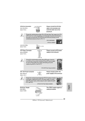
... it can still work if you adopt a traditional 20-pin ATX power supply. Pin 1-3 Connected 3-Pin Fan Installation (3-pin CPU_FAN2) (see p.2 No. 5) GND +12V CPU_FAN_SPEED ATX Power Connector (24-pin ATXPWR1) (see p.2 No.30) This COM1 header supports a serial port module. English 25 ASRock 970 Extreme3 Motherboard Though this motherboard provides 4-Pin CPU fan (Quiet Fan...
... it can still work if you adopt a traditional 20-pin ATX power supply. Pin 1-3 Connected 3-Pin Fan Installation (3-pin CPU_FAN2) (see p.2 No. 5) GND +12V CPU_FAN_SPEED ATX Power Connector (24-pin ATXPWR1) (see p.2 No.30) This COM1 header supports a serial port module. English 25 ASRock 970 Extreme3 Motherboard Though this motherboard provides 4-Pin CPU fan (Quiet Fan...

