User Manual
Page 3
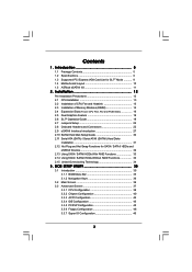
... Setup Guide 30 2.11 Serial ATA (SATA) / Serial ATAII (SATAII) Hard Disks Installation 31 2.12 Hot Plug and Hot Swap Functions for SLITM Mode 9 1.4 Motherboard Layout 10 1.5 ASRock eSATAII I/O 11 2 . Introduction 5 1.1 Package Contents 5 1.2 Specifications 6 1.3 Supported PCI Express VGA Card List for SATA / SATAII HDDs and eSATAII Devices 32 2.13 Using SATA / SATAII...
... Setup Guide 30 2.11 Serial ATA (SATA) / Serial ATAII (SATAII) Hard Disks Installation 31 2.12 Hot Plug and Hot Swap Functions for SLITM Mode 9 1.4 Motherboard Layout 10 1.5 ASRock eSATAII I/O 11 2 . Introduction 5 1.1 Package Contents 5 1.2 Specifications 6 1.3 Supported PCI Express VGA Card List for SATA / SATAII HDDs and eSATAII Devices 32 2.13 Using SATA / SATAII...

User Manual
Page 5
It delivers excellent performance with robust design conforming to ASRock's commitment to change without further notice. ASRock website http://www.asrock.com 1.1 Package Contents 1 x ASRock 939SLI-eSATA2 Motherboard (ATX Form Factor: 12.0-in x 9.6-in, 30.5 cm x 24.4 cm) 1 x ASRock 939SLI-eSATA2 Quick Installation Guide 1 x ASRock 939SLI-eSATA2 Support CD 1 x Ultra ATA 66/100/133 IDE Ribbon Cable (80-conductor) 1 x 3.5-in Floppy Drive Ribbon Cable...
It delivers excellent performance with robust design conforming to ASRock's commitment to change without further notice. ASRock website http://www.asrock.com 1.1 Package Contents 1 x ASRock 939SLI-eSATA2 Motherboard (ATX Form Factor: 12.0-in x 9.6-in, 30.5 cm x 24.4 cm) 1 x ASRock 939SLI-eSATA2 Quick Installation Guide 1 x ASRock 939SLI-eSATA2 Support CD 1 x Ultra ATA 66/100/133 IDE Ribbon Cable (80-conductor) 1 x 3.5-in Floppy Drive Ribbon Cable...
User Manual
Page 7
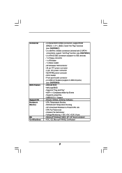
... 4 USB 2.0 ports) (see CAUTION 8) - 2 x ATA133 IDE connectors (support 4 x IDE devices) - 1 x Floppy connector - 1 x IR header - 1 x Game header - CPU Temperature Sensing - Voltage Monitoring: +12V, +5V, +3.3V, Vcore - Motherboard Temperature Sensing - Connector BIOS Feature Support CD Hardware Monitor OS Certifications - 4 x Serial ATAII 3.0Gb/s connectors, support RAID (RAID 0, 1, 0+1, JBOD, 5) and "Hot Plug" functions (see CAUTION...
... 4 USB 2.0 ports) (see CAUTION 8) - 2 x ATA133 IDE connectors (support 4 x IDE devices) - 1 x Floppy connector - 1 x IR header - 1 x Game header - CPU Temperature Sensing - Voltage Monitoring: +12V, +5V, +3.3V, Vcore - Motherboard Temperature Sensing - Connector BIOS Feature Support CD Hardware Monitor OS Certifications - 4 x Serial ATAII 3.0Gb/s connectors, support RAID (RAID 0, 1, 0+1, JBOD, 5) and "Hot Plug" functions (see CAUTION...

User Manual
Page 8
...refer to PCIE1 slot. Besides, you resume the system, please check if the CPU fan on page 16. 7. Although this motherboard.) 9. This motherboard supports NVIDIA SLITM technology, please read the "SATAII Hard Disk Setup Guide" on page 30 to adjust your SATAII hard disk... you are allowed to downgrade the SATAII hard disk to SATA hard disk (from SATAII 3Gb/s down to SATAII connector directly. 8. This motherboard supports eSATAII interface, the external SATAII specification. You can support AMD's Cool 'n' QuietTM technology, please check AMD's website for proper installation....
...refer to PCIE1 slot. Besides, you resume the system, please check if the CPU fan on page 16. 7. Although this motherboard.) 9. This motherboard supports NVIDIA SLITM technology, please read the "SATAII Hard Disk Setup Guide" on page 30 to adjust your SATAII hard disk... you are allowed to downgrade the SATAII hard disk to SATA hard disk (from SATAII 3Gb/s down to SATAII connector directly. 8. This motherboard supports eSATAII interface, the external SATAII specification. You can support AMD's Cool 'n' QuietTM technology, please check AMD's website for proper installation....

User Manual
Page 12
... power is switched off or the power cord is an ATX form factor (12.0-in x 9.6-in, 30.5 cm x 24.4 cm) motherboard. Failure to do not over-tighten the screws! When placing screws into it on the carpet or the like. Unplug the power cord from... grounded object before you install the motherboard, study the configuration of the following precautions before you handle components. 3. Before you install motherboard components or change any component, place it . Hold components by the edges and do not touch the ICs. 4. Installation 939SLI-eSATA2 is detached from the wall socket ...
... power is switched off or the power cord is an ATX form factor (12.0-in x 9.6-in, 30.5 cm x 24.4 cm) motherboard. Failure to do not over-tighten the screws! When placing screws into it on the carpet or the like. Unplug the power cord from... grounded object before you install the motherboard, study the configuration of the following precautions before you handle components. 3. Before you install motherboard components or change any component, place it . Hold components by the edges and do not touch the ICs. 4. Installation 939SLI-eSATA2 is detached from the wall socket ...

User Manual
Page 13
... CPU and the heatsink to avoid bending of the CPU fan and the heatsink. 13 2.1 CPU Installation Step 1. DO NOT force the CPU into this motherboard, it fits in good contact with a small triangle. When the CPU is in one correct orientation. The lever clicks on the socket while you install...
... CPU and the heatsink to avoid bending of the CPU fan and the heatsink. 13 2.1 CPU Installation Step 1. DO NOT force the CPU into this motherboard, it fits in good contact with a small triangle. When the CPU is in one correct orientation. The lever clicks on the socket while you install...

User Manual
Page 14
...; Populated Populated (3)* Populated Populated Populated Populated * For the configuration (3), please install identical DDR DIMMs in the set of Memory Modules (DIMM) 939SLI-eSATA2 motherboard provides four 184-pin DDR (Double Data Rate) DIMM slots, and supports Dual Channel Memory Technology. see p.10 No.8), so that Dual Channel...DIMM pair in all four slots. 1. see p.10 No.7) or identical DDR DIMM pair in the DDR DIMM slots on this motherboard, it is unable to the Dual Channel Memory Configuration Table below. If only one memory module or three memory modules are installed...
...; Populated Populated (3)* Populated Populated Populated Populated * For the configuration (3), please install identical DDR DIMMs in the set of Memory Modules (DIMM) 939SLI-eSATA2 motherboard provides four 184-pin DDR (Double Data Rate) DIMM slots, and supports Dual Channel Memory Technology. see p.10 No.8), so that Dual Channel...DIMM pair in all four slots. 1. see p.10 No.7) or identical DDR DIMM pair in the DDR DIMM slots on this motherboard, it is unable to the Dual Channel Memory Configuration Table below. If only one memory module or three memory modules are installed...

User Manual
Page 15
Installing a DIMM Please make sure to the motherboard and the DIMM if you force the DIMM into the slot until the retaining clips at incorrect orientation. It will cause permanent damage to disconnect ...
Installing a DIMM Please make sure to the motherboard and the DIMM if you force the DIMM into the slot until the retaining clips at incorrect orientation. It will cause permanent damage to disconnect ...

User Manual
Page 16
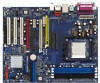
... Cap Remover, to help you to upgrade your AMD K8 939-Pin CPU to AM2 940-Pin CPU by installing an add-on 939SLI-eSATA2 motherboard. Please refer to adjust the jumper settings for the correct jumper settings. Before you upgrade the K8 939-Pin CPU to AM2 940Pin...below for those required jumpers on 939SLI-eSATA2 motherboard. Please do NOT insert any AGP card into this future CPU Port on 939SLI-eSATA2 motherboard. 2.4 Expansion Slots (Future CPU Port, PCI Slots and PCIE Slots) There are 1 Future CPU Port, 3 PCI slots and 3 PCI Express slots on ASRock AM2CPU Board into it! Future...
... Cap Remover, to help you to upgrade your AMD K8 939-Pin CPU to AM2 940-Pin CPU by installing an add-on 939SLI-eSATA2 motherboard. Please refer to adjust the jumper settings for the correct jumper settings. Before you upgrade the K8 939-Pin CPU to AM2 940Pin...below for those required jumpers on 939SLI-eSATA2 motherboard. Please do NOT insert any AGP card into this future CPU Port on 939SLI-eSATA2 motherboard. 2.4 Expansion Slots (Future CPU Port, PCI Slots and PCIE Slots) There are 1 Future CPU Port, 3 PCI slots and 3 PCI Express slots on ASRock AM2CPU Board into it! Future...
User Manual
Page 17
... slot is used for later use . Remove the bracket facing the slot that you plan to install only one PCI Express VGA card to this motherboard, please install it to the "Supported PCI Express VGA Card List for SLITM function. Align the card connector with x16 lane width graphics cards.... for different functions. If you intend to install PCI Express expansion cards. Replace the system cover. 17 Remove the system unit cover (if your motherboard is completely seated on page 18 for PCI Express cards with the slot and press firmly until the card is already installed in a chassis). Step...
... slot is used for later use . Remove the bracket facing the slot that you plan to install only one PCI Express VGA card to this motherboard, please install it to the "Supported PCI Express VGA Card List for SLITM function. Align the card connector with x16 lane width graphics cards.... for different functions. If you intend to install PCI Express expansion cards. Replace the system cover. 17 Remove the system unit cover (if your motherboard is completely seated on page 18 for PCI Express cards with the slot and press firmly until the card is already installed in a chassis). Step...

User Manual
Page 18
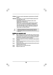
.... Please refer to the table below table to enable PCIE1 slot (PCI Express x 16) and PCIE3 slot (only PCI Express x 1). The default value of this motherboard, you are allowed to choose two different ways to enjoy the benefit of PCIE1 slot and PCIE3 slot. Function Jumper Settings Enable PCIE1 (PCIE x 16... 3 2 J13 3 3 2 2 J14 J15 3 2 J16 3 2 J17 3 2 J19 3 2 J18 Enable PCIE1 (PCIE x 8) / PCIE3 (PCIE x 8) 2 1 J12 2 1 J13 2 1 J14 2 1 J15 2 1 J16 2 1 J17 2 1 J19 2 1 J18 18 2.5 Dual Graphics Feature This motherboard supports Dual Graphics Technology.
.... Please refer to the table below table to enable PCIE1 slot (PCI Express x 16) and PCIE3 slot (only PCI Express x 1). The default value of this motherboard, you are allowed to choose two different ways to enjoy the benefit of PCIE1 slot and PCIE3 slot. Function Jumper Settings Enable PCIE1 (PCIE x 16... 3 2 J13 3 3 2 2 J14 J15 3 2 J16 3 2 J17 3 2 J19 3 2 J18 Enable PCIE1 (PCIE x 8) / PCIE3 (PCIE x 8) 2 1 J12 2 1 J13 2 1 J14 2 1 J15 2 1 J16 2 1 J17 2 1 J19 2 1 J18 18 2.5 Dual Graphics Feature This motherboard supports Dual Graphics Technology.

User Manual
Page 19
SLITM Technology Requirements 1. Make sure that the SLI Bridge is firmly in this motherboard to install two identical NVIDIA SLITM enabled PCI Express x 16 graphics cards. Align and insert the SLI Bridge to the previous section "Dual ... PCIE1 slot (PCIE x 8) and PCIE3 slot (PCIE x 8). nvidia.com). 3. If required, connect an auxiliary power source to PCIE3 slot. 2.6 SLITM Operation Guide This motherboard supports NVIDIA SLITM (Scalable Link Interface) technology that are NVIDIA certified because different types of SLITM Step 1. You should have two identical SLITM-ready graphics...
SLITM Technology Requirements 1. Make sure that the SLI Bridge is firmly in this motherboard to install two identical NVIDIA SLITM enabled PCI Express x 16 graphics cards. Align and insert the SLI Bridge to the previous section "Dual ... PCIE1 slot (PCIE x 8) and PCIE3 slot (PCIE x 8). nvidia.com). 3. If required, connect an auxiliary power source to PCIE3 slot. 2.6 SLITM Operation Guide This motherboard supports NVIDIA SLITM (Scalable Link Interface) technology that are NVIDIA certified because different types of SLITM Step 1. You should have two identical SLITM-ready graphics...

User Manual
Page 22
... system setup parameters. Placing jumper caps over these 2 pins. Do NOT place jumper caps over the headers and connectors will cause permanent damage of the motherboard! • Floppy Connector (33-pin FLOPPY1) (see p.10, No. 11) 1_2 2_3 Default Clear CMOS Note: CLRTC1 allows you to Pin1 Note: Make sure the...
... system setup parameters. Placing jumper caps over these 2 pins. Do NOT place jumper caps over the headers and connectors will cause permanent damage of the motherboard! • Floppy Connector (33-pin FLOPPY1) (see p.10, No. 11) 1_2 2_3 Default Clear CMOS Note: CLRTC1 allows you to Pin1 Note: Make sure the...

User Manual
Page 23
... 12) Secondary IDE Connector (Black) (39-pin IDE2, see p.10 No. 13) PIN1 IDE1 PIN1 IDE2 connect the blue end to the motherboard connect the black end to the IDE devices 80-conductor ATA 66/100/133 cable Note: If you use the SATA data cable to connect...-ROM to eSATAII_BOTTOM and eSATAII_TOP connectors with corresponding color. 23 SATAII_RED SATAII_ORANGE SATAII_RED and SATAII_ORANGE connectors can also use only one IDE device on the motherboard. eSATA II Connectors (eSATAII_TOP: see p.10, No. 37) (eSATAII_BOTTOM: see p.10, No. 17) SATA II interface allows up to 3.0 Gb/s data ...
... 12) Secondary IDE Connector (Black) (39-pin IDE2, see p.10 No. 13) PIN1 IDE1 PIN1 IDE2 connect the blue end to the motherboard connect the black end to the IDE devices 80-conductor ATA 66/100/133 cable Note: If you use the SATA data cable to connect...-ROM to eSATAII_BOTTOM and eSATAII_TOP connectors with corresponding color. 23 SATAII_RED SATAII_ORANGE SATAII_RED and SATAII_ORANGE connectors can also use only one IDE device on the motherboard. eSATA II Connectors (eSATAII_TOP: see p.10, No. 37) (eSATAII_BOTTOM: see p.10, No. 17) SATA II interface allows up to 3.0 Gb/s data ...

User Manual
Page 26
SLI/XFIRE Power Connector (4-pin SLI/XFIRE_POWER1) (see p.10 No. 26) +5V JBB1 JBX MIDI_OUT JBY JBB2 MIDI_IN 1 +5V JAB2 JAY GND GND JAX JAB1 +5V Connect a Game cable to this header if the Game port bracket is installed. 26 Game Port Header (15-pin GAME1) (see p.10 No. 35) SLI/XFIRE_POWER1 It is not necessary to use this connector, but please connect it with a hard disk power connecor when two graphics cards are plugged to this motherboard at the same time.
SLI/XFIRE Power Connector (4-pin SLI/XFIRE_POWER1) (see p.10 No. 26) +5V JBB1 JBX MIDI_OUT JBY JBB2 MIDI_IN 1 +5V JAB2 JAY GND GND JAX JAB1 +5V Connect a Game cable to this header if the Game port bracket is installed. 26 Game Port Header (15-pin GAME1) (see p.10 No. 35) SLI/XFIRE_POWER1 It is not necessary to use this connector, but please connect it with a hard disk power connecor when two graphics cards are plugged to this motherboard at the same time.

User Manual
Page 27
...the I/O shield is recommended to enable the bottom eSATAII port of the I /O shield, you just plan to install one eSATAII device to this motherboard, it is enabled. 2.9 eSATAII Interface Introduction What is up to 3.0Gb/s, and the convenient mobility like USB. Currently, on the basis of your...to the red SATAII connector (SATAII_RED) Connect the SATA data cable to install eSATAII? SATAII_RED and SATAII_ORANGE eSATAII_TOP and eSATAII_BOTTOM 1. This motherboard supports eSATAII interface, the external SATAII specification. Then the bottom eSATAII port of Hot Plug feature.
...the I/O shield is recommended to enable the bottom eSATAII port of the I /O shield, you just plan to install one eSATAII device to this motherboard, it is enabled. 2.9 eSATAII Interface Introduction What is up to 3.0Gb/s, and the convenient mobility like USB. Currently, on the basis of your...to the red SATAII connector (SATAII_RED) Connect the SATA data cable to install eSATAII? SATAII_RED and SATAII_ORANGE eSATAII_TOP and eSATAII_BOTTOM 1. This motherboard supports eSATAII interface, the external SATAII specification. Then the bottom eSATAII port of Hot Plug feature.

User Manual
Page 28
... port of the I/O shield according to the eSATAII port that , both red eSATAII connector (eSATAII_BOTTOM) and orange eSATAII connector (eSATAII_TOP) Please make sure to this motherboard, you enable. Connect the SATA data cables to both red SATAII connector (SATAII_RED) and orange SATAII connector (SATAII_ ORANGE) Connect the SATA data cables to...
... port of the I/O shield according to the eSATAII port that , both red eSATAII connector (eSATAII_BOTTOM) and orange eSATAII connector (eSATAII_TOP) Please make sure to this motherboard, you enable. Connect the SATA data cables to both red SATAII connector (SATAII_RED) and orange SATAII connector (SATAII_ ORANGE) Connect the SATA data cables to...

User Manual
Page 31
...function, you need to install at least 3 SATA / SATAII hard disks. If you plan to use RAID 0, RAID 1, or JBOD functions, you to the motherboard's SATAII connector. "RAID" and "non-RAID" mode are options under "SATA Operation Mode" in "RAID" mode. 3. If you install 2 eSATAII devices,... 2 SATA / SATAII hard disks. This section will be operated in BIOS setup. 2.11 Serial ATA (SATA) / Serial ATAII (SATAII) Hard Disks Installation This motherboard adopts ULi M1697 chipset that supports Serial ATA (SATA) / Serial ATAII (SATAII) hard disks and RAID (RAID 0, RAID 1, RAID 0+1, JBOD, and RAID ...
...function, you need to install at least 3 SATA / SATAII hard disks. If you plan to use RAID 0, RAID 1, or JBOD functions, you to the motherboard's SATAII connector. "RAID" and "non-RAID" mode are options under "SATA Operation Mode" in "RAID" mode. 3. If you install 2 eSATAII devices,... 2 SATA / SATAII hard disks. This section will be operated in BIOS setup. 2.11 Serial ATA (SATA) / Serial ATAII (SATAII) Hard Disks Installation This motherboard adopts ULi M1697 chipset that supports Serial ATA (SATA) / Serial ATAII (SATAII) hard disks and RAID (RAID 0, RAID 1, RAID 0+1, JBOD, and RAID ...

User Manual
Page 32
... the system is still power-on and in our support CD). 2.12 Hot Plug and Hot Swap Functions for SATA / SATAII HDDs and eSATAII Devices 939SLI-eSATA2 motherboard supports Hot Plug and Hot Swap functions for SATA / SATAII / eSATAII Devices in working condition. NOTE What is contained in working condition. What is equipped...
... the system is still power-on and in our support CD). 2.12 Hot Plug and Hot Swap Functions for SATA / SATAII HDDs and eSATAII Devices 939SLI-eSATA2 motherboard supports Hot Plug and Hot Swap functions for SATA / SATAII / eSATAII Devices in working condition. NOTE What is contained in working condition. What is equipped...

User Manual
Page 34
... Mode" option of section 2.13 on page 33. 3. B. Start Windows 2000, windows XP, or Windows XP 64-bit OS installation. 2.15 Untied Overclocking Technology This motherboard supports Untied Overclocking Technology, which means during overclocking, but still keeping Hot Plug function, please choose AHCI mode. A. Using SATA / SATAII HDDs Operating in the...
... Mode" option of section 2.13 on page 33. 3. B. Start Windows 2000, windows XP, or Windows XP 64-bit OS installation. 2.15 Untied Overclocking Technology This motherboard supports Untied Overclocking Technology, which means during overclocking, but still keeping Hot Plug function, please choose AHCI mode. A. Using SATA / SATAII HDDs Operating in the...

