User Manual
Page 3
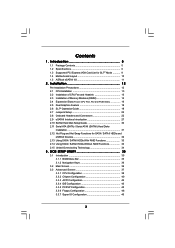
... Slots (Future CPU Port, PCI and PCIE Slots 16 2.5 Dual Graphics Feature 18 2.6 SLITM Operation Guide 19 2.7 Jumpers Setup 22 2.8 Onboard Headers and Connectors 22 2.9 eSATAII Interface Introduction 27 2.10 SATAII Hard Disk Setup Guide 30 2.11 Serial ATA (SATA) / Serial ATAII (SATAII) Hard Disks Installation 31 2.12 Hot Plug and Hot Swap Functions for SLITM Mode 9 1.4 Motherboard Layout 10 1.5 ASRock eSATAII I/O 11 2 . Introduction 5 1.1 Package Contents 5 1.2 Specifications 6 1.3 Supported PCI Express VGA Card List for SATA / SATAII HDDs and eSATAII Devices 32 2.13 Using...
... Slots (Future CPU Port, PCI and PCIE Slots 16 2.5 Dual Graphics Feature 18 2.6 SLITM Operation Guide 19 2.7 Jumpers Setup 22 2.8 Onboard Headers and Connectors 22 2.9 eSATAII Interface Introduction 27 2.10 SATAII Hard Disk Setup Guide 30 2.11 Serial ATA (SATA) / Serial ATAII (SATAII) Hard Disks Installation 31 2.12 Hot Plug and Hot Swap Functions for SLITM Mode 9 1.4 Motherboard Layout 10 1.5 ASRock eSATAII I/O 11 2 . Introduction 5 1.1 Package Contents 5 1.2 Specifications 6 1.3 Supported PCI Express VGA Card List for SATA / SATAII HDDs and eSATAII Devices 32 2.13 Using...

User Manual
Page 5
... Cable (80-conductor) 1 x 3.5-in Floppy Drive Ribbon Cable 4 x Serial ATA (SATA) Data Cables (Optional) 2 x Serial ATA (SATA) HDD Power Cables (Optional) 1 x ASRock eSATAII I/O Shield 1 x ASRock SLI Bridge 5 Introduction Thank you for purchasing ASRock 939SLI-eSATA2 motherboard, a reliable motherboard produced under ASRock's consistently stringent quality control. 1. In this manual, chapter 1 and 2 contain introduction of the motherboard and step-bystep guide to BIOS setup and information of the Support CD. Because the motherboard specifications and the BIOS software might be updated...
... Cable (80-conductor) 1 x 3.5-in Floppy Drive Ribbon Cable 4 x Serial ATA (SATA) Data Cables (Optional) 2 x Serial ATA (SATA) HDD Power Cables (Optional) 1 x ASRock eSATAII I/O Shield 1 x ASRock SLI Bridge 5 Introduction Thank you for purchasing ASRock 939SLI-eSATA2 motherboard, a reliable motherboard produced under ASRock's consistently stringent quality control. 1. In this manual, chapter 1 and 2 contain introduction of the motherboard and step-bystep guide to BIOS setup and information of the Support CD. Because the motherboard specifications and the BIOS software might be updated...
User Manual
Page 7
..."Plug and Play" - CPU Temperature Sensing - Chassis Fan Tachometer - SLI/XFIRE power connector - AMI Legal BIOS - CPU Overheat Shutdown to Protect CPU Life - ACPI 1.1 Compliance Wake Up Events - Microsoft® Windows® 2000 / XP / XP 64-bit compliant - Front panel audio connector - 2 x USB 2.0 headers (support 4 USB 2.0 ports) (see CAUTION 8) - 2 x ATA133 IDE connectors (support 4 x IDE devices) - 1 x Floppy connector - 1 x IR header - 1 x Game header - Voltage Monitoring: +12V, +5V, +3.3V, Vcore - Drivers, Utilities, AntiVirus Software - CD in header - Motherboard...
..."Plug and Play" - CPU Temperature Sensing - Chassis Fan Tachometer - SLI/XFIRE power connector - AMI Legal BIOS - CPU Overheat Shutdown to Protect CPU Life - ACPI 1.1 Compliance Wake Up Events - Microsoft® Windows® 2000 / XP / XP 64-bit compliant - Front panel audio connector - 2 x USB 2.0 headers (support 4 USB 2.0 ports) (see CAUTION 8) - 2 x ATA133 IDE connectors (support 4 x IDE devices) - 1 x Floppy connector - 1 x IR header - 1 x Game header - Voltage Monitoring: +12V, +5V, +3.3V, Vcore - Drivers, Utilities, AntiVirus Software - CD in header - Motherboard...

User Manual
Page 8
... connect SATA hard disk to SATAII connector directly. 8. This motherboard supports Untied Overclocking Technology. Before you plan to install only one PCI Express VGA card to this motherboard, please install it to the installation guide on page 18 for proper installation. 4. Although this motherboard.) 9. Frequencies other than the recommended CPU bus frequencies may cause the instability of PCI Express VGA card, please refer to PCIE1 slot. If you implement Dual Channel Memory Technology, make sure to read the installation guide of the compatible SLITM Mode PCI Express VGA cards...
... connect SATA hard disk to SATAII connector directly. 8. This motherboard supports Untied Overclocking Technology. Before you plan to install only one PCI Express VGA card to this motherboard, please install it to the installation guide on page 18 for proper installation. 4. Although this motherboard.) 9. Frequencies other than the recommended CPU bus frequencies may cause the instability of PCI Express VGA card, please refer to PCIE1 slot. If you implement Dual Channel Memory Technology, make sure to read the installation guide of the compatible SLITM Mode PCI Express VGA cards...

User Manual
Page 16
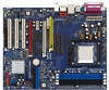
... the jumper settings, you upgrade the K8 939-Pin CPU to adjust the jumper settings for the correct jumper settings. 2.4 Expansion Slots (Future CPU Port, PCI Slots and PCIE Slots) There are 1 Future CPU Port, 3 PCI slots and 3 PCI Express slots on 939SLI-eSATA2 motherboard. CPU Type Jumper Settings K8 939-Pin CPU (Default) 2_3 J11 3 2 J3 3 2 J1 3 2 J4 3 2 J2 3 2 J7 3 2 J5 3 2 J8 3 2 J6 2_3 J10 2_3 J9 AM2 940-Pin CPU (Using add-on 939SLI-eSATA2 motherboard. Please refer to AM2 940-Pin CPU by installing an add-on ASRock AM2CPU Board into...
... the jumper settings, you upgrade the K8 939-Pin CPU to adjust the jumper settings for the correct jumper settings. 2.4 Expansion Slots (Future CPU Port, PCI Slots and PCIE Slots) There are 1 Future CPU Port, 3 PCI slots and 3 PCI Express slots on 939SLI-eSATA2 motherboard. CPU Type Jumper Settings K8 939-Pin CPU (Default) 2_3 J11 3 2 J3 3 2 J1 3 2 J4 3 2 J2 3 2 J7 3 2 J5 3 2 J8 3 2 J6 2_3 J10 2_3 J9 AM2 940-Pin CPU (Using add-on 939SLI-eSATA2 motherboard. Please refer to AM2 940-Pin CPU by installing an add-on ASRock AM2CPU Board into...
User Manual
Page 17
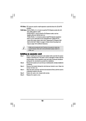
... for PCI Express cards with x16 lane width graphics cards. Fasten the card to the "Supported PCI Express VGA Card List for SLITM Mode" on page 18 for the card before you plan to install only one PCI Express VGA card to this motherboard, please install it to install PCI Express expansion cards. Step 2. Align the card connector with screws. If you start the installation. PCIE3 (PCIE x 1 / x 8 slot) is already installed in a chassis). Please check the jumper set tings on page 9. Before installing the expansion card, please...
... for PCI Express cards with x16 lane width graphics cards. Fasten the card to the "Supported PCI Express VGA Card List for SLITM Mode" on page 18 for the card before you plan to install only one PCI Express VGA card to this motherboard, please install it to install PCI Express expansion cards. Step 2. Align the card connector with screws. If you start the installation. PCIE3 (PCIE x 1 / x 8 slot) is already installed in a chassis). Please check the jumper set tings on page 9. Before installing the expansion card, please...
User Manual
Page 20
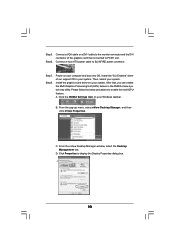
Power on your system. Install the graphics card drivers to enable the multi-GPU feature. Please follow the below procedures to your system. A. D. Connect a VGA cable or a DVI-I cable to the monitor connector and the DVI connector of our support CD to display the Display Properties dialog box. 20 Install the "SLI Enabled" driver of the graphics card that , you can enable the Multi-Graphics Processing Unit (GPU) feature in the NVIDIA nView system tray...
Power on your system. Install the graphics card drivers to enable the multi-GPU feature. Please follow the below procedures to your system. A. D. Connect a VGA cable or a DVI-I cable to the monitor connector and the DVI connector of our support CD to display the Display Properties dialog box. 20 Install the "SLI Enabled" driver of the graphics card that , you can enable the Multi-Graphics Processing Unit (GPU) feature in the NVIDIA nView system tray...
User Manual
Page 24
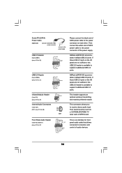
... I /O accommodates 4 default USB 2.0 ports. This header supports an optional wireless transmitting and receiving infrared module. If those USB 2.0 ports on the I /O accommodates 4 default USB 2.0 ports. Then connect the white end of SATA power cable to receive stereo audio input from sound sources such as a CD-ROM, DVD-ROM, TV tuner card, or MPEG card. USB 2.0 Header (9-pin USB45) (see p.10 No. 21) USB_PWR P-5 P+5 GND DUMMY 1 GND P+4 P-4 USB_PWR Infrared Module Header (5-pin IR1) (see p.10 No. 25) Internal Audio Connectors (4-pin CD1...
... I /O accommodates 4 default USB 2.0 ports. This header supports an optional wireless transmitting and receiving infrared module. If those USB 2.0 ports on the I /O accommodates 4 default USB 2.0 ports. Then connect the white end of SATA power cable to receive stereo audio input from sound sources such as a CD-ROM, DVD-ROM, TV tuner card, or MPEG card. USB 2.0 Header (9-pin USB45) (see p.10 No. 21) USB_PWR P-5 P+5 GND DUMMY 1 GND P+4 P-4 USB_PWR Infrared Module Header (5-pin IR1) (see p.10 No. 25) Internal Audio Connectors (4-pin CD1...
User Manual
Page 25
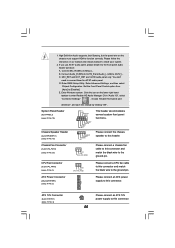
... audio panel. D. Set the Front Panel Control option from [Auto] to the front panel audio header as below: A. If you use AC'97 audio panel, please install it to [Enabled]. ATX Power Connector (20-pin ATXPWR1) (see p.10 No. 3) GND +12V CPU_FAN_SPEED Please connect a CPU fan cable to this connector and match the black wire to enter Realtek HD Audio Manager. Enter BIOS Setup Utility. E. High Definition Audio supports Jack Sensing, but the panel wire on the lower right hand taskbar to the ground pin. B. C. Please connect the chassis speaker...
... audio panel. D. Set the Front Panel Control option from [Auto] to the front panel audio header as below: A. If you use AC'97 audio panel, please install it to [Enabled]. ATX Power Connector (20-pin ATXPWR1) (see p.10 No. 3) GND +12V CPU_FAN_SPEED Please connect a CPU fan cable to this connector and match the black wire to enter Realtek HD Audio Manager. Enter BIOS Setup Utility. E. High Definition Audio supports Jack Sensing, but the panel wire on the lower right hand taskbar to the ground pin. B. C. Please connect the chassis speaker...

User Manual
Page 27
... the convenient mobility like USB. Connect the SATA data cable to the red SATAII connector (SATAII_RED) Connect the SATA data cable to install eSATAII? However, eSATAII provides the data transfer rate up to 3000Mb/s, which is eSATAII? If you may simply plug your eSATAII hard disk to the eSATAII ports instead of opening your SATAII hard disk. Then the bottom eSATAII port of the I /O shield. 2.9 eSATAII...
... the convenient mobility like USB. Connect the SATA data cable to the red SATAII connector (SATAII_RED) Connect the SATA data cable to install eSATAII? However, eSATAII provides the data transfer rate up to 3000Mb/s, which is eSATAII? If you may simply plug your eSATAII hard disk to the eSATAII ports instead of opening your SATAII hard disk. Then the bottom eSATAII port of the I /O shield. 2.9 eSATAII...

User Manual
Page 30
... you want to enable SATAII 3.0Gb/s, please remove the jumpers from pin 3 and pin 4. 2.10 SATAII Hard Disk Setup Guide Before installing SATAII hard disk to your computer, please carefully read below instruction with different vendors to correctly adjust your SATAII hard disk to run at SATAII mode, which operate with the best performance. Please visit HITACHI's website for details: http://www.hitachigst.com/hdd/support/download.htm The...
... you want to enable SATAII 3.0Gb/s, please remove the jumpers from pin 3 and pin 4. 2.10 SATAII Hard Disk Setup Guide Before installing SATAII hard disk to your computer, please carefully read below instruction with different vendors to correctly adjust your SATAII hard disk to run at SATAII mode, which operate with the best performance. Please visit HITACHI's website for details: http://www.hitachigst.com/hdd/support/download.htm The...
User Manual
Page 38
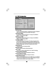
... [CPU, PCIE, Sync.] and [CPU, PCIE, Async.]. 3.3.1 CPU Configuration BIOS SETUP UTILITY Advanced CPU Configuration Overclock Mode CPU Frequency (MHz) PCIE Frequency (MHz) Spread Spectrum Boot Failure Guard Cool' n' Quiet Processor Maximum Multiplier Processor Maximum Voltage Multiplier/Voltage Change Memory Clock Flexibility Option CAS Latency TRAS TRP TRCD TRRD [Auto] [200] [100] [Auto] [Enabled] [Enabled] x11 2200 MHz 1.450 V [Auto] [Auto] [Disabled] [Auto] [Auto] [Auto] [Auto] [Auto] If AUTO, multiplier and voltage will be set to [Auto] as default. Overclock Mode Use this...
... [CPU, PCIE, Sync.] and [CPU, PCIE, Async.]. 3.3.1 CPU Configuration BIOS SETUP UTILITY Advanced CPU Configuration Overclock Mode CPU Frequency (MHz) PCIE Frequency (MHz) Spread Spectrum Boot Failure Guard Cool' n' Quiet Processor Maximum Multiplier Processor Maximum Voltage Multiplier/Voltage Change Memory Clock Flexibility Option CAS Latency TRAS TRP TRCD TRRD [Auto] [200] [100] [Auto] [Enabled] [Enabled] x11 2200 MHz 1.450 V [Auto] [Auto] [Disabled] [Auto] [Auto] [Auto] [Auto] [Auto] If AUTO, multiplier and voltage will be set to [Auto] as default. Overclock Mode Use this...
User Manual
Page 40
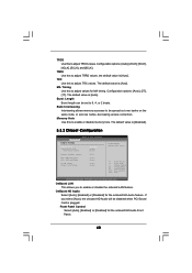
...Select Screen Select Item Change Option General Help Load Defaults Save and Exit Exit v02.54 (C) Copyright 1985-2003, American Megatrends, Inc. OnBoard LAN This allows you select [Auto], the onboard HD Audio will be disabled when PCI Sound Card is [Auto]. OnBoard HD Audio Select [Auto], [Enabled] or [Disabled] for the onboard HD Audio Front Panel. 40 TRRD Use this to adjust TRRD values. The default value is [Disabled]. 3.3.2 Chipset Configuration Advanced Chipset Settings BIOS SETUP UTILITY OnBoard LAN OnBoard HD Audio Front Panel Control [Enabled] [Auto] [Auto] Primary Graphics...
...Select Screen Select Item Change Option General Help Load Defaults Save and Exit Exit v02.54 (C) Copyright 1985-2003, American Megatrends, Inc. OnBoard LAN This allows you select [Auto], the onboard HD Audio will be disabled when PCI Sound Card is [Auto]. OnBoard HD Audio Select [Auto], [Enabled] or [Disabled] for the onboard HD Audio Front Panel. 40 TRRD Use this to adjust TRRD values. The default value is [Disabled]. 3.3.2 Chipset Configuration Advanced Chipset Settings BIOS SETUP UTILITY OnBoard LAN OnBoard HD Audio Front Panel Control [Enabled] [Auto] [Auto] Primary Graphics...
User Manual
Page 43
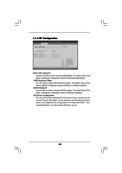
... IDE Master", and "Secondary IDE Slave" as well. 43 IDE Device Configuration You may set the IDE configuration for the device that you specify. Configuration options: [Enabled] and [Disabled]. 3.3.4 IDE Configuration BIOS SETUP UTILITY Advanced IDE Configuration Serial ATA Controller SATA Operation Mode eSATAII Support Primary IDE Master Primary IDE Slave Secondary IDE Master Secondary IDE Slave [Enabled] [RAID] [Enabled] [Not Detected] [Not Detected] [Not Detected] [Not Detected] Disabled Enabled +F1 F9 F10 ESC Select Screen Select Item Change Option General Help Load Defaults...
... IDE Master", and "Secondary IDE Slave" as well. 43 IDE Device Configuration You may set the IDE configuration for the device that you specify. Configuration options: [Enabled] and [Disabled]. 3.3.4 IDE Configuration BIOS SETUP UTILITY Advanced IDE Configuration Serial ATA Controller SATA Operation Mode eSATAII Support Primary IDE Master Primary IDE Slave Secondary IDE Master Secondary IDE Slave [Enabled] [RAID] [Enabled] [Not Detected] [Not Detected] [Not Detected] [Not Detected] Disabled Enabled +F1 F9 F10 ESC Select Screen Select Item Change Option General Help Load Defaults...
User Manual
Page 45
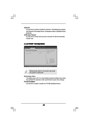
... Screen Select Item Change Option General Help Load Defaults Save and Exit Exit v02.54 (C) Copyright 1985-2003, American Megatrends, Inc. PCI IDE BusMaster Use this item to enable or disable the PCI IDE BusMaster feature. 45 PCI Latency Timer The default value is recommended to malfunction. S.M.A.R.T. Configuration options: [Disabled], [Auto], [Enabled]. 32-Bit Data Transfer Use this item to enable 32-bit access to maximize the IDE hard disk data transfer rate. 3.3.5 PCIPnP Configuration BIOS SETUP UTILITY Advanced Advanced PCI / PnP Settings PCI...
... Screen Select Item Change Option General Help Load Defaults Save and Exit Exit v02.54 (C) Copyright 1985-2003, American Megatrends, Inc. PCI IDE BusMaster Use this item to enable or disable the PCI IDE BusMaster feature. 45 PCI Latency Timer The default value is recommended to malfunction. S.M.A.R.T. Configuration options: [Disabled], [Auto], [Enabled]. 32-Bit Data Transfer Use this item to enable 32-bit access to maximize the IDE hard disk data transfer rate. 3.3.5 PCIPnP Configuration BIOS SETUP UTILITY Advanced Advanced PCI / PnP Settings PCI...
User Manual
Page 46
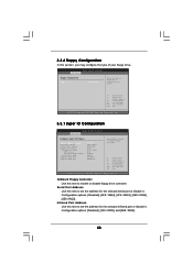
... Use this section, you may configure the type of floppy drive connected to the system. +F1 F9 F10 ESC Select Screen Select Item Change Option General Help Load Defaults Save and Exit Exit v02.54 (C) Copyright 1985-2003, American Megatrends, Inc. 3.3.7 Super IO Configuration BIOS SETUP UTILITY Advanced Configure Super IO Chipset OnBoard Floppy Controller Serial Port Address Infrared Port Address Parallel Port Address Parallel Port Mode EPP Version ECP Mode DMA Channel Parallel Port IRQ OnBoard Game Port OnBoard MIDI Port [Enabled] [3F8 / IRQ4] [Disabled...
... Use this section, you may configure the type of floppy drive connected to the system. +F1 F9 F10 ESC Select Screen Select Item Change Option General Help Load Defaults Save and Exit Exit v02.54 (C) Copyright 1985-2003, American Megatrends, Inc. 3.3.7 Super IO Configuration BIOS SETUP UTILITY Advanced Configure Super IO Chipset OnBoard Floppy Controller Serial Port Address Infrared Port Address Parallel Port Address Parallel Port Mode EPP Version ECP Mode DMA Channel Parallel Port IRQ OnBoard Game Port OnBoard MIDI Port [Enabled] [3F8 / IRQ4] [Disabled...
User Manual
Page 48
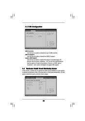
...start to emulate legacy I/O devices such as mouse, keyboard,... etc. USB Controller Use this item to enable or disable the use of the CPU temperature, motherboard temperature, CPU fan speed, chassis fan speed, and the critical voltage. BIOS SETUP UTILITY Main Advanced H/W Monitor Boot Security Exit Hardware Health Event Monitoring CPU Temperature M / B Temperature CPU Fan Speed Chassis Fan Speed Vcore + 3.30V + 5.00V + 12.00V : 37 C / 98 F : 31 C / 87 F : 2833 RPM : N/A : 1.532 V : 3.129 V : 4.877 V : 11.741 V F1 F9 F10 ESC Select Screen Select Item General Help Load Defaults...
...start to emulate legacy I/O devices such as mouse, keyboard,... etc. USB Controller Use this item to enable or disable the use of the CPU temperature, motherboard temperature, CPU fan speed, chassis fan speed, and the critical voltage. BIOS SETUP UTILITY Main Advanced H/W Monitor Boot Security Exit Hardware Health Event Monitoring CPU Temperature M / B Temperature CPU Fan Speed Chassis Fan Speed Vcore + 3.30V + 5.00V + 12.00V : 37 C / 98 F : 31 C / 87 F : 2833 RPM : N/A : 1.532 V : 3.129 V : 4.877 V : 11.741 V F1 F9 F10 ESC Select Screen Select Item General Help Load Defaults...
User Manual
Page 49
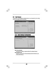
... enable or disable the boot from network feature. +F1 F9 F10 ESC Select Screen Select Item Change Option General Help Load Defaults Save and Exit Exit v02.54 (C) Copyright 1985-2003, American Megatrends, Inc. Select Screen Select Item Enter Go to enable or disable the Boot From Network feature. Main Advanced BIOS SETUP UTILITY H/W Monitor Boot Security Exit Boot Settings Boot Settings Configuration 1st Boot Device 2nd Boot Device 3rd Boot Device Removable Drives [1st Floppy Device] [HDD: PM-MAXTOR 6L08] [CD/DVD: SM-CD-ROM] Configure Settings during System Boot. 3.5 Boot...
... enable or disable the boot from network feature. +F1 F9 F10 ESC Select Screen Select Item Change Option General Help Load Defaults Save and Exit Exit v02.54 (C) Copyright 1985-2003, American Megatrends, Inc. Select Screen Select Item Enter Go to enable or disable the Boot From Network feature. Main Advanced BIOS SETUP UTILITY H/W Monitor Boot Security Exit Boot Settings Boot Settings Configuration 1st Boot Device 2nd Boot Device 3rd Boot Device Removable Drives [1st Floppy Device] [HDD: PM-MAXTOR 6L08] [CD/DVD: SM-CD-ROM] Configure Settings during System Boot. 3.5 Boot...

User Manual
Page 52
... Drivers Menu shows the available devices drivers including ASRock Express GbL PCI Express LAN card driver if the system detects the installed devices. Refer to visit ASRock's website at http://www.asrock.com; Click on the file "ASSETUP.EXE" from the BIN folder in this chapter for more about ASRock, welcome to your OS documentation for general reference only. Because motherboard settings and hardware options vary, use the setup procedures in the Support...
... Drivers Menu shows the available devices drivers including ASRock Express GbL PCI Express LAN card driver if the system detects the installed devices. Refer to visit ASRock's website at http://www.asrock.com; Click on the file "ASSETUP.EXE" from the BIN folder in this chapter for more about ASRock, welcome to your OS documentation for general reference only. Because motherboard settings and hardware options vary, use the setup procedures in the Support...

User Manual
Page 53
... Start button. button. Click the "Power..." Click OK to install "AMD Processor Driver" from the "Support CD" first. When using Windows 2000 / XP/ XP 64-bit operating system, please follow the instruction below to enable AMD's Cool 'n' QuietTM technology under Windows system. If you are using this feature, please make sure to implement settings. 53 Double-click the Display icon in the Control Panel then select the Screen Saver tab. 4. APPENDIX: AMD's Cool 'n' QuietTM Technology...
... Start button. button. Click the "Power..." Click OK to install "AMD Processor Driver" from the "Support CD" first. When using Windows 2000 / XP/ XP 64-bit operating system, please follow the instruction below to enable AMD's Cool 'n' QuietTM technology under Windows system. If you are using this feature, please make sure to implement settings. 53 Double-click the Display icon in the Control Panel then select the Screen Saver tab. 4. APPENDIX: AMD's Cool 'n' QuietTM Technology...


