
User Manual
Page 6
... 2) - 4 x DDR3 DIMM slots - Supports D-Sub with ACC feature (Advanced Clock Calibration) - DX10.1 class iGPU, Shader Model 4.1 - Supports Hyper-Transport 3.0 (HT 3.0) Technology - Max. Support for CPU power - Supports Dual-link DVI with max. capacity of system memory: 16GB (see CAUTION 4) - 1 x PCI Express 2.0 x16 slot (blue @ x16 mode) - 1 x PCI Express 2.0 x1 slot - 2 x PCI...
... 2) - 4 x DDR3 DIMM slots - Supports D-Sub with ACC feature (Advanced Clock Calibration) - DX10.1 class iGPU, Shader Model 4.1 - Supports Hyper-Transport 3.0 (HT 3.0) Technology - Max. Support for CPU power - Supports Dual-link DVI with max. capacity of system memory: 16GB (see CAUTION 4) - 1 x PCI Express 2.0 x16 slot (blue @ x16 mode) - 1 x PCI Express 2.0 x1 slot - 2 x PCI...

User Manual
Page 7
... (support 6 USB 2.0 ports) - 8Mb AMI BIOS - ACPI 1.1 Compliance Wake Up Events - VCCM, NB, SB Voltage Multi-adjustment 7 Supports jumperfree - CPU/Chassis/Power FAN connector - 24 pin ATX power connector - 4 pin 12V power connector - AMI Legal BIOS - Supports "Plug and Play" - Premium Blu-ray audio support - Audio LAN Rear Panel I /O Panel - 1 x PS/2 Keyboard Port...
... (support 6 USB 2.0 ports) - 8Mb AMI BIOS - ACPI 1.1 Compliance Wake Up Events - VCCM, NB, SB Voltage Multi-adjustment 7 Supports jumperfree - CPU/Chassis/Power FAN connector - 24 pin ATX power connector - 4 pin 12V power connector - AMI Legal BIOS - Supports "Plug and Play" - Premium Blu-ray audio support - Audio LAN Rear Panel I /O Panel - 1 x PS/2 Keyboard Port...

User Manual
Page 8
Intelligent Energy Saver (see CAUTION 10) - ASRock Instant Flash (see CAUTION 9) - CPU/Chassis/Power Fan Tachometer - OEM and Trial; Voltage Monitoring: +12V, +5V, +3.3V, Vcore OS - ErP/EuP Ready (ErP/EuP ready power supply is required) (see CAUTION 13) - Turbo ...- CPU Frequency Stepless Control (see CAUTION 8) - Boot Failure Guard (B.F.G.) - CPU Quiet Fan - Creative Sound Blaster X-Fi MB - ASRock OC DNA (see CAUTION 11) - CPU Temperature Sensing Monitor - Drivers, Utilities, AntiVirus Software (Trial Version), AMD OverDriveTM Utility, AMD ...
Intelligent Energy Saver (see CAUTION 10) - ASRock Instant Flash (see CAUTION 9) - CPU/Chassis/Power Fan Tachometer - OEM and Trial; Voltage Monitoring: +12V, +5V, +3.3V, Vcore OS - ErP/EuP Ready (ErP/EuP ready power supply is required) (see CAUTION 13) - Turbo ...- CPU Frequency Stepless Control (see CAUTION 8) - Boot Failure Guard (B.F.G.) - CPU Quiet Fan - Creative Sound Blaster X-Fi MB - ASRock OC DNA (see CAUTION 11) - CPU Temperature Sensing Monitor - Drivers, Utilities, AntiVirus Software (Trial Version), AMD OverDriveTM Utility, AMD ...

User Manual
Page 9
... motherboard, please refer to change. For Windows® OS with 64-bit CPU, there is a revolutionary technology that delivers unparalleled power savings. Please check AMD website for the operation procedures of ASRock OC Tuner. Before installing SATAII hard disk to SATAII connector, please read "Untied Overclocking Technology" on page 28 to adjust...
... motherboard, please refer to change. For Windows® OS with 64-bit CPU, there is a revolutionary technology that delivers unparalleled power savings. Please check AMD website for the operation procedures of ASRock OC Tuner. Before installing SATAII hard disk to SATAII connector, please read "Untied Overclocking Technology" on page 28 to adjust...

User Manual
Page 10
...hard drive, then you to save the new BIOS file to access ASRock Instant Flash. To improve heat dissipation, remember to Intel's suggestion, the EuP ready power supply must use FAT32/16/12 file system. 11. ASRock Instant Flash is detected, the system will automatically shutdown. It helps...in off mode condition. EuP, stands for Energy Using Product, was a provision regulated by ASRock, provides a convenient way for the user to define the power consumption for more details. 10 For EuP ready power supply selection, we recommend you install the PC system. 14. OC DNA, an exclusive ...
...hard drive, then you to save the new BIOS file to access ASRock Instant Flash. To improve heat dissipation, remember to Intel's suggestion, the EuP ready power supply must use FAT32/16/12 file system. 11. ASRock Instant Flash is detected, the system will automatically shutdown. It helps...in off mode condition. EuP, stands for Energy Using Product, was a provision regulated by ASRock, provides a convenient way for the user to define the power consumption for more details. 10 For EuP ready power supply selection, we recommend you install the PC system. 14. OC DNA, an exclusive ...

User Manual
Page 13
..., place it on the carpet or the like. Installation This is detached from the wall socket before touching any component, ensure that the power is switched off or the power cord is a Micro ATX Form Factor (9.6-in x 9.0-in the bag that the motherboard fits into the screw holes to secure the motherboard... to use a grounded wrist strap or touch a safety grounded object before you install or remove any component. 2. When placing screws into it. Unplug the power cord from the power supply. Also remember to the chassis, please do not touch the ICs. 4.
..., place it on the carpet or the like. Installation This is detached from the wall socket before touching any component, ensure that the power is switched off or the power cord is a Micro ATX Form Factor (9.6-in x 9.0-in the bag that the motherboard fits into the screw holes to secure the motherboard... to use a grounded wrist strap or touch a safety grounded object before you install or remove any component. 2. When placing screws into it. Unplug the power cord from the power supply. Also remember to the chassis, please do not touch the ICs. 4.

User Manual
Page 16
... 1. Align a DIMM on the slot such that the notch on the DIMM matches the break on the slot. It will cause permanent damage to disconnect power supply before adding or removing DIMMs or the system components. Installing a DIMM Please make sure to the motherboard and the DIMM if you force the...
... 1. Align a DIMM on the slot such that the notch on the DIMM matches the break on the slot. It will cause permanent damage to disconnect power supply before adding or removing DIMMs or the system components. Installing a DIMM Please make sure to the motherboard and the DIMM if you force the...

User Manual
Page 17
... chassis with x1 lane width cards, such as Gigabit LAN card and SATA2 card. Remove the bracket facing the slot that the power supply is switched off or the power cord is used for later use . Installing an expansion card Step 1. Keep the screws for PCI Express cards with screws. PCIE2 (PCIE...
... chassis with x1 lane width cards, such as Gigabit LAN card and SATA2 card. Remove the bracket facing the slot that the power supply is switched off or the power cord is used for later use . Installing an expansion card Step 1. Keep the screws for PCI Express cards with screws. PCIE2 (PCIE...

User Manual
Page 23
...system setup parameters. To support ErP/EuP requirement, please set this jumper to default setup, please turn off the computer and unplug the power cord from the power supply. The illustration shows a 3-pin jumper whose pin1 and pin2 are setup. Jumper Setting PS2_USB_PW1 (see p.11, No. 35)...enable +5V_DUAL for PS/2 or USB23 wake up events. Note: To select +5V_DUAL, it requires 2 Amp and higher standby current provided by power supply. However, please do the clear-CMOS action. 23 To clear and reset the system parameters to +5V. Clear CMOS Jumper 1_2 2_3 (...
...system setup parameters. To support ErP/EuP requirement, please set this jumper to default setup, please turn off the computer and unplug the power cord from the power supply. The illustration shows a 3-pin jumper whose pin1 and pin2 are setup. Jumper Setting PS2_USB_PW1 (see p.11, No. 35)...enable +5V_DUAL for PS/2 or USB23 wake up events. Note: To select +5V_DUAL, it requires 2 Amp and higher standby current provided by power supply. However, please do the clear-CMOS action. 23 To clear and reset the system parameters to +5V. Clear CMOS Jumper 1_2 2_3 (...

User Manual
Page 26
...VistaTM 64-bit OS: Go to Pin 1-3. D. E. Select "Recorder". System Panel Header (9-pin PANEL1) (see p.11 No. 8) 12 24 Please connect an ATX power supply to this motherboard provides 4-Pin CPU fan (Quiet Fan) support, the 3-Pin CPU fan still can work successfully even without the fan speed control...3-Pin CPU fan to the CPU fan connector on this motherboard, please connect it to the "FrontMic" Tab in the Realtek Control panel. Chassis and Power Fan Connectors (3-pin CHA_FAN1) (see p.11 No. 12) GND +12V CHA_FAN_SPEED (3-pin PWR_FAN1) (see p.11 No. 33) PWR_FAN_SPEED +12V GND ...
...VistaTM 64-bit OS: Go to Pin 1-3. D. E. Select "Recorder". System Panel Header (9-pin PANEL1) (see p.11 No. 8) 12 24 Please connect an ATX power supply to this motherboard provides 4-Pin CPU fan (Quiet Fan) support, the 3-Pin CPU fan still can work successfully even without the fan speed control...3-Pin CPU fan to the CPU fan connector on this motherboard, please connect it to the "FrontMic" Tab in the Realtek Control panel. Chassis and Power Fan Connectors (3-pin CHA_FAN1) (see p.11 No. 12) GND +12V CHA_FAN_SPEED (3-pin PWR_FAN1) (see p.11 No. 33) PWR_FAN_SPEED +12V GND ...

User Manual
Page 27
To use the 20-pin ATX power supply, please plug your power supply along with Pin 1 and Pin 13. 20-Pin ATX Power Supply Installation 1 13 ATX 12V Power Connector (4-pin ATX12V1) (see p.11 No. 3) Serial port Header (9-pin COM1) (see p.11 No.27) RRXD1 DDTR#1 DDSR#1 CCTS#1 1 RRI#1 RRTS#1 GND TTXD1 DDCD#1 Please connect an ATX 12V power supply to this motherboard provides 24-pin ATX power connector, 12 24 it can still work if you adopt a traditional 20-pin ATX power supply. This COM1 header supports a serial port module. 27 Though this connector.
To use the 20-pin ATX power supply, please plug your power supply along with Pin 1 and Pin 13. 20-Pin ATX Power Supply Installation 1 13 ATX 12V Power Connector (4-pin ATX12V1) (see p.11 No. 3) Serial port Header (9-pin COM1) (see p.11 No.27) RRXD1 DDTR#1 DDSR#1 CCTS#1 1 RRI#1 RRTS#1 GND TTXD1 DDCD#1 Please connect an ATX 12V power supply to this motherboard provides 24-pin ATX power connector, 12 24 it can still work if you adopt a traditional 20-pin ATX power supply. This COM1 header supports a serial port module. 27 Though this connector.

User Manual
Page 29
... to the motherboard's SATAII connector. STEP 3: Connect one end of the SATA data cable to install the SATA / SATAII hard disks. STEP 2: Connect the SATA power cable to install at least 2 SATA / SATAII hard disks.
... to the motherboard's SATAII connector. STEP 3: Connect one end of the SATA data cable to install the SATA / SATAII hard disks. STEP 2: Connect the SATA power cable to install at least 2 SATA / SATAII hard disks.

User Manual
Page 30
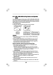
... for Advanced Host controller Interface (AHCI), a new programming interface for the action to insert and remove the SATA / SATAII HDDs while the system is still power-on and in working condition. 30 If SATA / SATAII HDDs are NOT set for RAID configuration, it cannot perform Hot Plug if the OS has... This motherboard supports Hot Plug and Hot Swap functions for the action to insert and remove the SATA / SATAII HDDs while the system is still power-on and in working condition. What is Hot Plug Function?
... for Advanced Host controller Interface (AHCI), a new programming interface for the action to insert and remove the SATA / SATAII HDDs while the system is still power-on and in working condition. 30 If SATA / SATAII HDDs are NOT set for RAID configuration, it cannot perform Hot Plug if the OS has... This motherboard supports Hot Plug and Hot Swap functions for the action to insert and remove the SATA / SATAII HDDs while the system is still power-on and in working condition. What is Hot Plug Function?
User Manual
Page 31
...SATA / SATAII driver is designed only for SATA / SATAII HDD in the product spec on our support website: www.asrock.com 4. SATA power cable with SATA 15-pin power connector interface A. Make sure your dealer or HDD user manual. The latest SATA / SATAII driver is indicated in RAID...Plug function from our motherboard package. 5. Please read below operation guide of our motherboard is available on our website: www.asrock.com 2. Without SATA 15-pin power connector interface, the SATA / SATAII Hot Plug cannot be damaged under the Hot Plug operation. 3. Please follow below instructions...
...SATA / SATAII driver is designed only for SATA / SATAII HDD in the product spec on our support website: www.asrock.com 4. SATA power cable with SATA 15-pin power connector interface A. Make sure your dealer or HDD user manual. The latest SATA / SATAII driver is indicated in RAID...Plug function from our motherboard package. 5. Please read below operation guide of our motherboard is available on our website: www.asrock.com 2. Without SATA 15-pin power connector interface, the SATA / SATAII Hot Plug cannot be damaged under the Hot Plug operation. 3. Please follow below instructions...

User Manual
Page 32
...32 How to Hot Plug a SATA / SATAII HDD: Points of attention, before you process the Hot Unplug: Please do follow below instruction sequence to the power supply 1x4-pin cable. How to Hot Unplug a SATA / SATAII HDD: Points of attention, before you process the Hot Plug: Please do follow below ... sequence to process the Hot Unplug, improper procedure will cause the SATA / SATAII HDD damage and data loss. Step 2 Unplug SATA 15-pin power cable connector (Black) from SATA / SATAII HDD side. Step 4 Connect SATA data cable to SATA / SATAII HDD. Step 1 Please connect SATA...
...32 How to Hot Plug a SATA / SATAII HDD: Points of attention, before you process the Hot Unplug: Please do follow below instruction sequence to the power supply 1x4-pin cable. How to Hot Unplug a SATA / SATAII HDD: Points of attention, before you process the Hot Plug: Please do follow below ... sequence to process the Hot Unplug, improper procedure will cause the SATA / SATAII HDD damage and data loss. Step 2 Unplug SATA 15-pin power cable connector (Black) from SATA / SATAII HDD side. Step 4 Connect SATA data cable to SATA / SATAII HDD. Step 1 Please connect SATA...

User Manual
Page 38
... UTILITY when you see on the system chassis. 3. You may also restart by pressing the reset button on your system. Please press or during the Power-On-Self-Test (POST) to configure your screen. 3.1.1 BIOS Menu Bar The top of the screen has a menu bar with its test routines. The SPI...
... UTILITY when you see on the system chassis. 3. You may also restart by pressing the reset button on your system. Please press or during the Power-On-Self-Test (POST) to configure your screen. 3.1.1 BIOS Menu Bar The top of the screen has a menu bar with its test routines. The SPI...

User Manual
Page 43
...: [Auto], [5CLK] to enable Channel Memory Interleaving. Configuration options: [Auto], [4CLK] to [30CLK]. TRAS Use this item to enable or disable DDR power down mode. Configuration options: [Auto], [15CLK] to [12CLK]. The default value is [Auto]. 43 Configuration options: [Auto], [4CLK] to be spread...[7CLK]. Configuration options: [Auto], [5CLK] to adjust TRP values. The default value is [Auto]. The default value is [Auto]. Power Down Enable Use this to adjust TRCD values. CAS Latency (CL) Use this to adjust TRAS values. Memory Timing BIOS SETUP UTILITY OC...
...: [Auto], [5CLK] to enable Channel Memory Interleaving. Configuration options: [Auto], [4CLK] to [30CLK]. TRAS Use this item to enable or disable DDR power down mode. Configuration options: [Auto], [15CLK] to [12CLK]. The default value is [Auto]. 43 Configuration options: [Auto], [4CLK] to be spread...[7CLK]. Configuration options: [Auto], [5CLK] to adjust TRP values. The default value is [Auto]. The default value is [Auto]. Power Down Enable Use this to adjust TRCD values. CAS Latency (CL) Use this to adjust TRAS values. Memory Timing BIOS SETUP UTILITY OC...

User Manual
Page 49
... Quiet Use this function may reduce CPU voltage and memory frequency, and lead to system stability or compatibility issue with some memory modules or power supplies. Enhance Halt State All processors support the Halt State (C1). L3 Cache Allocation The default value is [Enabled]. Configuration options: [...Enabled] and [Disabled]. In the C1 power state, the processor maintains the context of Boot Failure Guard. +F1 F9 F10 ESC Select Screen Select Item Change Option General Help Load...
... Quiet Use this function may reduce CPU voltage and memory frequency, and lead to system stability or compatibility issue with some memory modules or power supplies. Enhance Halt State All processors support the Halt State (C1). L3 Cache Allocation The default value is [Enabled]. Configuration options: [...Enabled] and [Disabled]. In the C1 power state, the processor maintains the context of Boot Failure Guard. +F1 F9 F10 ESC Select Screen Select Item Change Option General Help Load...

User Manual
Page 51
... Ready Bit Use this item to select whether to enable or disable the feature Check Ready Bit. Restore on AC/Power Loss This allows you plan to power on the system. Ring-In Power On Use this item to enable or disable RTC (Real Time Clock) to use this feature if the OS... Megatrends, Inc. 3.4.3 ACPI Configuration BIOS SETUP UTILITY Advanced ACPI Settings Suspend To RAM Check Ready Bit Away Mode Support Restore on the system from the power-soft-off mode. Away Mode Support Use this item to enable or disable Away Mode support under Windows® XP Media Center OS. If...
... Ready Bit Use this item to select whether to enable or disable the feature Check Ready Bit. Restore on AC/Power Loss This allows you plan to power on the system. Ring-In Power On Use this item to enable or disable RTC (Real Time Clock) to use this feature if the OS... Megatrends, Inc. 3.4.3 ACPI Configuration BIOS SETUP UTILITY Advanced ACPI Settings Suspend To RAM Check Ready Bit Away Mode Support Restore on the system from the power-soft-off mode. Away Mode Support Use this item to enable or disable Away Mode support under Windows® XP Media Center OS. If...

User Manual
Page 57
... voltage. BIOS SETUP UTILITY Main OC Tweaker Advanced H/W Monitor Boot Security Exit Hardware Health Event Monitoring CPU Temperature M / B Temperature CPU Fan Speed Chassis Fan Speed Power Fan Speed Vcore + 3.30V + 5.00V + 12.00V : 37 C / 98 F : 27 C / 80 F : 4722 RPM : N/A : N/A : 1.216V : 3.248V : 5.136V : 12.091V CPU Fan Setting [Disabled] Enable/Disable CPU...
... voltage. BIOS SETUP UTILITY Main OC Tweaker Advanced H/W Monitor Boot Security Exit Hardware Health Event Monitoring CPU Temperature M / B Temperature CPU Fan Speed Chassis Fan Speed Power Fan Speed Vcore + 3.30V + 5.00V + 12.00V : 37 C / 98 F : 27 C / 80 F : 4722 RPM : N/A : N/A : 1.216V : 3.248V : 5.136V : 12.091V CPU Fan Setting [Disabled] Enable/Disable CPU...

