User Manual
Page 8
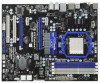
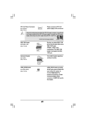
... Center / XP 64-bit compliant Certifications - - Voltage Monitoring: +12V, +5V, +3.3V, Vcore OS - ErP/EuP Ready (ErP/EuP ready power supply is required) (see CAUTION 11) - We are not responsible for possible damage caused by overclocking. 8 FCC, CE, WHQL - CPU Frequency Stepless ...Control (see CAUTION 13) * For detailed product information, please visit our website: http://www.asrock.com WARNING Please realize that there is a certain risk involved with overclocking, including adjusting the setting in the BIOS, applying Untied...
... Center / XP 64-bit compliant Certifications - - Voltage Monitoring: +12V, +5V, +3.3V, Vcore OS - ErP/EuP Ready (ErP/EuP ready power supply is required) (see CAUTION 11) - We are not responsible for possible damage caused by overclocking. 8 FCC, CE, WHQL - CPU Frequency Stepless ...Control (see CAUTION 13) * For detailed product information, please visit our website: http://www.asrock.com WARNING Please realize that there is a certain risk involved with overclocking, including adjusting the setting in the BIOS, applying Untied...
User Manual
Page 10
...a BIOS flash utility embedded in Flash ROM. According to access ASRock Instant Flash. For EuP ready power supply selection, we recommend you what it is capable of. OC DNA literally tells you checking with the power supply manufacturer for more details. 10 Your friends then can update your ...must meet EuP standard, an EuP ready motherboard and an EuP ready power supply are required. With OC DNA, you install the PC system. 13. EuP, stands for Energy Using Product, was a provision regulated by ASRock, provides a convenient way for the completed system. Although this tool...
...a BIOS flash utility embedded in Flash ROM. According to access ASRock Instant Flash. For EuP ready power supply selection, we recommend you what it is capable of. OC DNA literally tells you checking with the power supply manufacturer for more details. 10 Your friends then can update your ...must meet EuP standard, an EuP ready motherboard and an EuP ready power supply are required. With OC DNA, you install the PC system. 13. EuP, stands for Energy Using Product, was a provision regulated by ASRock, provides a convenient way for the completed system. Although this tool...
User Manual
Page 13
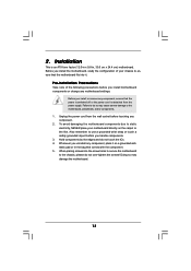
...the motherboard fits into the screw holes to secure the motherboard to the motherboard, peripherals, and/or components. 1. Failure to ensure that the power is switched off or the power cord is an ATX form factor (12.0-in x 9.6-in the bag that comes with the component. 5. To avoid damaging the motherboard ... the screws! Installation This is detached from the wall socket before you install or remove any motherboard settings. Before you handle components. 3. Unplug the power cord from the power supply. When placing screws into it on the carpet or the like. 2.
...the motherboard fits into the screw holes to secure the motherboard to the motherboard, peripherals, and/or components. 1. Failure to ensure that the power is switched off or the power cord is an ATX form factor (12.0-in x 9.6-in the bag that comes with the component. 5. To avoid damaging the motherboard ... the screws! Installation This is detached from the wall socket before you install or remove any motherboard settings. Before you handle components. 3. Unplug the power cord from the power supply. When placing screws into it on the carpet or the like. 2.
User Manual
Page 16
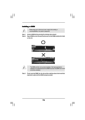
... slot. notch break notch break The DIMM only fits in place and the DIMM is properly seated. 16 It will cause permanent damage to disconnect power supply before adding or removing DIMMs or the system components. Firmly insert the DIMM into the slot at both ends fully snap back in one correct...
... slot. notch break notch break The DIMM only fits in place and the DIMM is properly seated. 16 It will cause permanent damage to disconnect power supply before adding or removing DIMMs or the system components. Firmly insert the DIMM into the slot at both ends fully snap back in one correct...
User Manual
Page 17
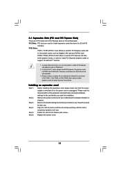
... two slots will work at x8 bandwidth. 3. PCIE Slots: PCIE1 / PCIE3 (PCIE x1 slot; Remove the bracket facing the slot that the power supply is switched off or the power cord is used to install PCI Express graphics cards to install a PCI Express x16 graphics card on this motherboard. Replace the system cover...
... two slots will work at x8 bandwidth. 3. PCIE Slots: PCIE1 / PCIE3 (PCIE x1 slot; Remove the bracket facing the slot that the power supply is switched off or the power cord is used to install PCI Express graphics cards to install a PCI Express x16 graphics card on this motherboard. Replace the system cover...
User Manual
Page 23
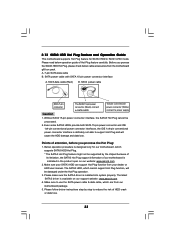
...5 seconds. To support ErP/EuP requirement, please set this jumper to default setup, please turn off the computer and unplug the power cord from the power supply. If you need to clear the data in CMOS includes system setup information such as system password, date, time, and system ...setup parameters. Note: To select +5VSB, it requires 2 Amp and higher standby current provided by power supply. When you update the BIOS. 2.7 Jumpers Setup The illustration shows how jumpers are "Short" when jumper cap is "Short". Note: To select ...
...5 seconds. To support ErP/EuP requirement, please set this jumper to default setup, please turn off the computer and unplug the power cord from the power supply. If you need to clear the data in CMOS includes system setup information such as system password, date, time, and system ...setup parameters. Note: To select +5VSB, it requires 2 Amp and higher standby current provided by power supply. When you update the BIOS. 2.7 Jumpers Setup The illustration shows how jumpers are "Short" when jumper cap is "Short". Note: To select ...
User Manual
Page 26
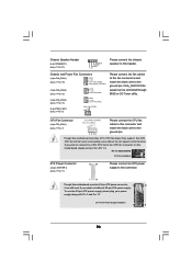
...12) (3-pin CHA_FAN3) (see p.11 No. 13) (3-pin PWR_FAN1) (see p.11 No. 11) 12 24 Please connect an ATX power supply to this connector. 1 13 Though this motherboard provides 24-pin ATX power connector, 12 24 it to the CPU fan connector on this motherboard provides 4-Pin CPU fan (Quiet Fan) support, the...Tuner utility. CHA_FAN1/2/3 fan speed can work if you plan to connect the 3-Pin CPU fan to Pin 1-3. To use the 20-pin ATX power supply, please plug your power supply along with Pin 1 and Pin 13. 20-Pin ATX Power Supply Installation 1 13 26 If you adopt a traditional 20-pin ATX...
...12) (3-pin CHA_FAN3) (see p.11 No. 13) (3-pin PWR_FAN1) (see p.11 No. 11) 12 24 Please connect an ATX power supply to this connector. 1 13 Though this motherboard provides 24-pin ATX power connector, 12 24 it to the CPU fan connector on this motherboard provides 4-Pin CPU fan (Quiet Fan) support, the...Tuner utility. CHA_FAN1/2/3 fan speed can work if you plan to connect the 3-Pin CPU fan to Pin 1-3. To use the 20-pin ATX power supply, please plug your power supply along with Pin 1 and Pin 13. 20-Pin ATX Power Supply Installation 1 13 26 If you adopt a traditional 20-pin ATX...
User Manual
Page 27
..., it can support one IEEE 1394 header (FRONT_1394) on the I/O panel, there is one IEEE 1394 port. To use the 4-pin ATX power supply, please plug your power supply along with Pin 1 and Pin 5. 8 5 IEEE 1394 Header (9-pin FRONT_1394) (see p.11 No. 25) Serial port Header (9-pin COM1) (...see p.11 No. 3) 4 1 Please connect an ATX 12V power supply to this connector. HDMI_SPDIF Header (2-pin HDMI_SPDIF1) (see p.11 No. 33) 1 GND SPDIFOUT HDMI_SPDIF header, providing SPDIF audio output to HDMI VGA card, allows...
..., it can support one IEEE 1394 header (FRONT_1394) on the I/O panel, there is one IEEE 1394 port. To use the 4-pin ATX power supply, please plug your power supply along with Pin 1 and Pin 5. 8 5 IEEE 1394 Header (9-pin FRONT_1394) (see p.11 No. 25) Serial port Header (9-pin COM1) (...see p.11 No. 3) 4 1 Please connect an ATX 12V power supply to this connector. HDMI_SPDIF Header (2-pin HDMI_SPDIF1) (see p.11 No. 33) 1 GND SPDIFOUT HDMI_SPDIF header, providing SPDIF audio output to HDMI VGA card, allows...
User Manual
Page 33
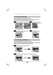
Make sure to power supply 1. Before you process the Hot Plug: 1. SATA power cable with SATA 15-pin power connector interface A. SATA power cable SATA 7-pin connector Caution The SATA 15-pin power connector (Black) connect to SATA3 HDD 1x4-pin conventional power connector (White) connect to use the SATA power cable & data cable,... 2. Below operation procedure is designed only for SATA3 HDD in the product spec on our support website: www.asrock.com 4. The latest SATA3 driver is indicated in RAID / AHCI mode. SATA data cable (Red) B. A. 7-pin SATA data cable B. The SATA3...
Make sure to power supply 1. Before you process the Hot Plug: 1. SATA power cable with SATA 15-pin power connector interface A. SATA power cable SATA 7-pin connector Caution The SATA 15-pin power connector (Black) connect to SATA3 HDD 1x4-pin conventional power connector (White) connect to use the SATA power cable & data cable,... 2. Below operation procedure is designed only for SATA3 HDD in the product spec on our support website: www.asrock.com 4. The latest SATA3 driver is indicated in RAID / AHCI mode. SATA data cable (Red) B. A. 7-pin SATA data cable B. The SATA3...
User Manual
Page 34
... 2 Connect SATA data cable to (White) to the SATA3 HDD. Step 4 Connect SATA data cable to the power supply 1x4-pin cable. SATA power cable 1x4-pin power connector (White) Step 3 Connect SATA 15-pin power cable connector (Black) end to SATA3 HDD. How to Hot Unplug a SATA3 HDD: Points of attention, before... will cause the SATA3 HDD damage and data loss. Step 1 Unplug SATA data cable from SATA3 HDD side. 34 Step 2 Unplug SATA 15-pin power cable connector (Black) from SATA3 HDD side. How to Hot Plug a SATA3 HDD: Points of attention, before you process the Hot Unplug: Please ...
... 2 Connect SATA data cable to (White) to the SATA3 HDD. Step 4 Connect SATA data cable to the power supply 1x4-pin cable. SATA power cable 1x4-pin power connector (White) Step 3 Connect SATA 15-pin power cable connector (Black) end to SATA3 HDD. How to Hot Unplug a SATA3 HDD: Points of attention, before... will cause the SATA3 HDD damage and data loss. Step 1 Unplug SATA data cable from SATA3 HDD side. 34 Step 2 Unplug SATA 15-pin power cable connector (Black) from SATA3 HDD side. How to Hot Plug a SATA3 HDD: Points of attention, before you process the Hot Unplug: Please ...
User Manual
Page 50
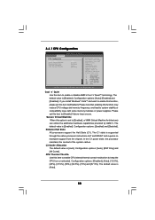
... that enabling this function may reduce CPU voltage and memory freq., and lead to system stability or compatibility issue with some memory modules or power supplies. The default value is [Enabled]. Enhance Halt State All processors support the Halt State (C1). Secure Virtual Machine When this item to... this function may reduce CPU voltage and memory frequency, and lead to system stability or compatibility issue with some memory modules or power supplies. Cool 'n' Quiet Use this item to enable CPU internal thermal control mechanism to keep the CPU from the chipset.
... that enabling this function may reduce CPU voltage and memory freq., and lead to system stability or compatibility issue with some memory modules or power supplies. The default value is [Enabled]. Enhance Halt State All processors support the Halt State (C1). Secure Virtual Machine When this item to... this function may reduce CPU voltage and memory frequency, and lead to system stability or compatibility issue with some memory modules or power supplies. Cool 'n' Quiet Use this item to enable CPU internal thermal control mechanism to keep the CPU from the chipset.

