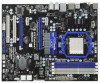

RAID Installation Guide
Page 2
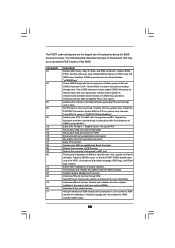
... the disk array management software will cause data damage or data loss. After you make a SATA / SATAII / SATA3 driver diskette, press or to enter BIOS setup to set of disk mirroring (RAID 1). The controller combines the performance of data striping (RAID 0) and the fault tolerance of drives. Although RAID 0 function can be...
... the disk array management software will cause data damage or data loss. After you make a SATA / SATAII / SATA3 driver diskette, press or to enter BIOS setup to set of disk mirroring (RAID 1). The controller combines the performance of data striping (RAID 0) and the fault tolerance of drives. Although RAID 0 function can be...
RAID Installation Guide
Page 4
...Please insert a floppy diskette into floppy drive A: press any key. When 4 STEP 1: Set up , press key, and then a window for boot devices selection appears. Then you need to the BIOS RAID installation guide part in this RAID installation guide for details. E. STEP 4: Install Windows...SATA / SATAII / SATA3 drivers into the floppy diskette. Please refer to check this document for proper configuration. D. Insert the ASRock Support CD into your optical drive to boot your data first before you see these messages, Please insert a blank formatted diskette ...
...Please insert a floppy diskette into floppy drive A: press any key. When 4 STEP 1: Set up , press key, and then a window for boot devices selection appears. Then you need to the BIOS RAID installation guide part in this RAID installation guide for details. E. STEP 4: Install Windows...SATA / SATAII / SATA3 drivers into the floppy diskette. Please refer to check this document for proper configuration. D. Insert the ASRock Support CD into your optical drive to boot your data first before you see these messages, Please insert a blank formatted diskette ...
RAID Installation Guide
Page 5
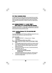
After reading the floppy disk, the driver will be presented. Enter BIOS SETUP UTILITY → Advanced screen →Storage Configuration. Select your system. 5 STEP 1: Set up BIOS. Before you start to configure RAID function, you want to install Windows 7 / 7 64-bit / Vista / Vista 64-bit on your required driver to install according ...
After reading the floppy disk, the driver will be presented. Enter BIOS SETUP UTILITY → Advanced screen →Storage Configuration. Select your system. 5 STEP 1: Set up BIOS. Before you start to configure RAID function, you want to install Windows 7 / 7 64-bit / Vista / Vista 64-bit on your required driver to install according ...
User Manual
Page 4
... 39 3.1.1 BIOS Menu Bar 39 3.1.2 Navigation Keys 40 3.2 Main Screen 40 3.3 OC Tweaker Screen 41 3.4 Advanced Screen 49 3.4.1 CPU Configuration 50 3.4.2 Chipset Configuration 51 3.4.3 ACPI Configuration 52 3.4.4 Storage Configuration 53 3.4.5 PCIPnP Configuration 55 3.4.6 Super IO Configuration 56 3.4.7 USB Configuration 57 3.5 Hardware Health Event Monitoring Screen 58 3.6 Boot Screen 59 3.6.1 Boot Settings Configuration...
... 39 3.1.1 BIOS Menu Bar 39 3.1.2 Navigation Keys 40 3.2 Main Screen 40 3.3 OC Tweaker Screen 41 3.4 Advanced Screen 49 3.4.1 CPU Configuration 50 3.4.2 Chipset Configuration 51 3.4.3 ACPI Configuration 52 3.4.4 Storage Configuration 53 3.4.5 PCIPnP Configuration 55 3.4.6 Super IO Configuration 56 3.4.7 USB Configuration 57 3.5 Hardware Health Event Monitoring Screen 58 3.6 Boot Screen 59 3.6.1 Boot Settings Configuration...
User Manual
Page 8
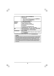
... information, please visit our website: http://www.asrock.com WARNING Please realize that there is required) (see CAUTION 12) - Voltage Monitoring: +12V, +5V, +3.3V, Vcore OS - ErP/EuP Ready (ErP/EuP ready power supply is a certain risk involved with overclocking, including adjusting the setting in the BIOS, applying Untied Overclocking Technology, or using...
... information, please visit our website: http://www.asrock.com WARNING Please realize that there is required) (see CAUTION 12) - Voltage Monitoring: +12V, +5V, +3.3V, Vcore OS - ErP/EuP Ready (ErP/EuP ready power supply is a certain risk involved with overclocking, including adjusting the setting in the BIOS, applying Untied Overclocking Technology, or using...
User Manual
Page 10
...perform over-clocking. To meet the standard of overclocking settings. For EuP ready power supply selection, we recommend you to update system BIOS without preparing an additional floppy diskette or other than 50% under 1.00W in Flash ROM. ASRock Instant Flash is higher than the recommended CPU bus...OC DNA, an exclusive utility developed by European Union to define the power consumption for the user to access ASRock Instant Flash. Your friends then can save your OC settings as yours! Although this utility, you resume the system, please check if the CPU fan on the ...
...perform over-clocking. To meet the standard of overclocking settings. For EuP ready power supply selection, we recommend you to update system BIOS without preparing an additional floppy diskette or other than 50% under 1.00W in Flash ROM. ASRock Instant Flash is higher than the recommended CPU bus...OC DNA, an exclusive utility developed by European Union to define the power consumption for the user to access ASRock Instant Flash. Your friends then can save your OC settings as yours! Although this utility, you resume the system, please check if the CPU fan on the ...
User Manual
Page 23
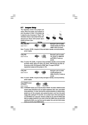
... and USB3_01 wake up the system under S3 (Suspend to clear the CMOS when you just finish updating the BIOS, you to +5V. To support ErP/EuP requirement, please set this jumper to clear the data in CMOS includes system setup information such as system password, date, time,...current provided by power supply. 2.7 Jumpers Setup The illustration shows how jumpers are "Short" when jumper cap is placed on these 2 pins. Jumper Setting PS2_USB_PW1 1_2 2_3 Short pin2, pin3 to enable +5VSB (standby) for 15 seconds, use a jumper cap to default setup, please turn off ...
... and USB3_01 wake up the system under S3 (Suspend to clear the CMOS when you just finish updating the BIOS, you to +5V. To support ErP/EuP requirement, please set this jumper to clear the data in CMOS includes system setup information such as system password, date, time,...current provided by power supply. 2.7 Jumpers Setup The illustration shows how jumpers are "Short" when jumper cap is placed on these 2 pins. Jumper Setting PS2_USB_PW1 1_2 2_3 Short pin2, pin3 to enable +5VSB (standby) for 15 seconds, use a jumper cap to default setup, please turn off ...
User Manual
Page 29
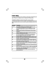
... D9 DA Description Early chipset initialization is forced. Determine whether to determine if BIOS recovery is done. Leaves all RAM below for future use in scratch CMOS. Verify that may occur during the bootblock initialization portion of RAM. Set stack. Bootblock code is copied from power management suspend state. Check if waking...
... D9 DA Description Early chipset initialization is forced. Determine whether to determine if BIOS recovery is done. Leaves all RAM below for future use in scratch CMOS. Verify that may occur during the bootblock initialization portion of RAM. Set stack. Bootblock code is copied from power management suspend state. Check if waking...
User Manual
Page 30
The following table describes the type of checkpoints that are the largest set up boot strap proccessor for POST Enumerate and set of checkpoints during the POST portion of the BIOS: Checkpoint 03 04 05 06 08 C0 C1 C2 C5 C6 C7 0A 0B 0C 0E 13 24 30 2A 2C 2E 31... Description Disable NMI, Parity, video for system timer interrupt. Initialize BIOS, POST, Runtime data area...
The following table describes the type of checkpoints that are the largest set up boot strap proccessor for POST Enumerate and set of checkpoints during the POST portion of the BIOS: Checkpoint 03 04 05 06 08 C0 C1 C2 C5 C6 C7 0A 0B 0C 0E 13 24 30 2A 2C 2E 31... Description Disable NMI, Parity, video for system timer interrupt. Initialize BIOS, POST, Runtime data area...
User Manual
Page 31
...Program the peripheral parameters. Initialize the CPU's before booting to OS Loader (typically INT19h). 31 A9 Wait for error. 87 Execute BIOS setup if needed . B1 Save system context for OS boot including final MTRR values. A8 Prepare CPU for ACPI. 00 Passes control...total memory installed in memory test. Also, Check for Int 19 boot. A4 Initialize runtime language module. Deinitializes the ADM module. Set the window for displaying text information. 37 Displaying sign-on message, CPU information, setup key message, and any kind of implementation that...
...Program the peripheral parameters. Initialize the CPU's before booting to OS Loader (typically INT19h). 31 A9 Wait for error. 87 Execute BIOS setup if needed . B1 Save system context for OS boot including final MTRR values. A8 Prepare CPU for ACPI. 00 Passes control...total memory installed in memory test. Also, Check for Int 19 boot. A4 Initialize runtime language module. Deinitializes the ADM module. Set the window for displaying text information. 37 Displaying sign-on message, CPU information, setup key message, and any kind of implementation that...
User Manual
Page 35
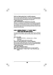
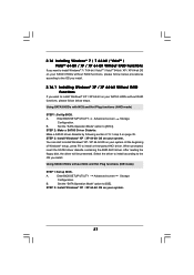
...to install Windows® 7 / 7 64-bit / VistaTM / VistaTM 64-bit / XP / XP 64-bit on a RAID disk composed of system boot-up BIOS. B. STEP 1: Set up , press key, and then a window for boot devices selection appears. 2.14 Driver Installation Guide To install the drivers to your system, please insert the... support CD to [RAID]. C. Then, the drivers compatible to install those required drivers. ROM as the boot device. D. Insert the ASRock Support CD into the floppy diskette. 35 E. Set the "SATA Operation Mode" option to your optical drive first.
...to install Windows® 7 / 7 64-bit / VistaTM / VistaTM 64-bit / XP / XP 64-bit on a RAID disk composed of system boot-up BIOS. B. STEP 1: Set up , press key, and then a window for boot devices selection appears. 2.14 Driver Installation Guide To install the drivers to your system, please insert the... support CD to [RAID]. C. Then, the drivers compatible to install those required drivers. ROM as the boot device. D. Insert the ASRock Support CD into the floppy diskette. 35 E. Set the "SATA Operation Mode" option to your optical drive first.
User Manual
Page 36
...will be presented. STEP 1: Set up BIOS. B. Set the "SATA Operation Mode" option to install Windows® XP / XP 64-bit OS on your system. Enter BIOS SETUP UTILITY Advanced screen Storage Configuration. STEP 3: Use "RAID Installation Guide" to the BIOS RAID installation guide part of ...the document in the following path in the Support CD: .. \ RAID Installation Guide STEP 4: Install Windows® XP / XP 64-bit OS on your system. Please refer to set RAID configuration. A. STEP 4: Install Windows®...
...will be presented. STEP 1: Set up BIOS. B. Set the "SATA Operation Mode" option to install Windows® XP / XP 64-bit OS on your system. Enter BIOS SETUP UTILITY Advanced screen Storage Configuration. STEP 3: Use "RAID Installation Guide" to the BIOS RAID installation guide part of ...the document in the following path in the Support CD: .. \ RAID Installation Guide STEP 4: Install Windows® XP / XP 64-bit OS on your system. Please refer to set RAID configuration. A. STEP 4: Install Windows®...
User Manual
Page 37
...15.1 step 2 on your SATA3 HDDs without NCQ and Hot Plug functions (IDE mode) STEP 1: Set up BIOS. A. When prompted, insert the SATA3 driver diskette containing the AMD AHCI driver. Set the "SATA Operation Mode" option to install a third-party AHCI driver. After reading the floppy disk...the OS you install. 2.16.1 Installing Windows® XP / XP 64-bit Without RAID Functions If you install. B. Enter BIOS SETUP UTILITY Advanced screen Storage Configuration. A. Set the "SATA Operation Mode" option to install Windows® XP / XP 64-bit OS on page 35. You can start...
...15.1 step 2 on your SATA3 HDDs without NCQ and Hot Plug functions (IDE mode) STEP 1: Set up BIOS. A. When prompted, insert the SATA3 driver diskette containing the AMD AHCI driver. Set the "SATA Operation Mode" option to install a third-party AHCI driver. After reading the floppy disk...the OS you install. 2.16.1 Installing Windows® XP / XP 64-bit Without RAID Functions If you install. B. Enter BIOS SETUP UTILITY Advanced screen Storage Configuration. A. Set the "SATA Operation Mode" option to install Windows® XP / XP 64-bit OS on page 35. You can start...
User Manual
Page 38
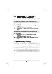
...B. Using SATA3 HDDs without RAID functions, please follow below steps. A. Using SATA3 HDDs with NCQ and Hot Plug functions (AHCI mode) STEP 1: Set Up BIOS. STEP 2: Install Windows® 7 / 7 64-bit / VistaTM / VistaTM 64-bit OS on your system. 2.17 Untied Overclocking Technology This ...bit OS on page 8 for the possible overclocking risk before you enable Untied Overclocking function, please enter "Overclock Mode" option of BIOS setup to set the selection from [Auto] to [CPU, PCIE, Async.]. Therefore, CPU FSB is untied during overclocking, FSB enjoys better margin due...
...B. Using SATA3 HDDs without RAID functions, please follow below steps. A. Using SATA3 HDDs with NCQ and Hot Plug functions (AHCI mode) STEP 1: Set Up BIOS. STEP 2: Install Windows® 7 / 7 64-bit / VistaTM / VistaTM 64-bit OS on your system. 2.17 Untied Overclocking Technology This ...bit OS on page 8 for the possible overclocking risk before you enable Untied Overclocking function, please enter "Overclock Mode" option of BIOS setup to set the selection from [Auto] to [CPU, PCIE, Async.]. Therefore, CPU FSB is untied during overclocking, FSB enjoys better margin due...
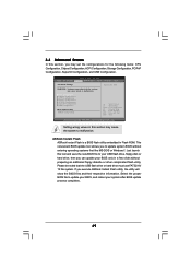
User Manual
Page 39
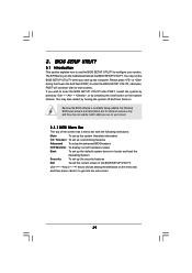
...date information OC Tweaker To set up overclocking features Advanced To set up the advanced BIOS features H/W Monitor To display current hardware status Boot To set up the default system device to locate and load the Operating System Security To set up the computer. BIOS SETUP UTILITY 3.1 Introduction ...This section explains how to use the BIOS SETUP UTILITY to configure your screen. 3.1.1 BIOS Menu Bar The top of the screen has a menu bar with ...
...date information OC Tweaker To set up overclocking features Advanced To set up the advanced BIOS features H/W Monitor To display current hardware status Boot To set up the default system device to locate and load the Operating System Security To set up the computer. BIOS SETUP UTILITY 3.1 Introduction ...This section explains how to use the BIOS SETUP UTILITY to configure your screen. 3.1.1 BIOS Menu Bar The top of the screen has a menu bar with ...
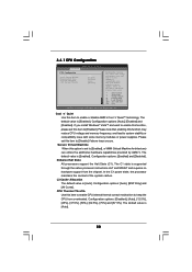
User Manual
Page 40
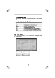
... Defaults Save and Exit Exit v02.54 (C) Copyright 1985-2005, American Megatrends, Inc. 3.1.2 Navigation Keys Please check the following table for all the settings To save changes and exit the BIOS SETUP UTILITY To jump to the Exit Screen or exit the current screen 3.2 Main Screen When you enter the... UTILITY Main OC Tweaker Advanced H/W Monitor System Overview System Time System Date [17:00:09] [Fri 04/02/2010] BIOS Version : 870 Extreme3 P1.00 Processor Type : AMD Phenom(tm) II X2 555 Processor (64bit) Processor Speed : 3200MHz Microcode Update : 100F43/10000B6 L1 Cache Size : 256KB L2...
... Defaults Save and Exit Exit v02.54 (C) Copyright 1985-2005, American Megatrends, Inc. 3.1.2 Navigation Keys Please check the following table for all the settings To save changes and exit the BIOS SETUP UTILITY To jump to the Exit Screen or exit the current screen 3.2 Main Screen When you enter the... UTILITY Main OC Tweaker Advanced H/W Monitor System Overview System Time System Date [17:00:09] [Fri 04/02/2010] BIOS Version : 870 Extreme3 P1.00 Processor Type : AMD Phenom(tm) II X2 555 Processor (64bit) Processor Speed : 3200MHz Microcode Update : 100F43/10000B6 L1 Cache Size : 256KB L2...
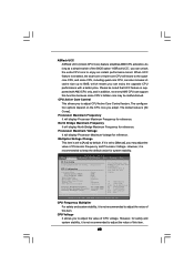
User Manual
Page 41
... Configuration Overclock Mode Use this option to load the optiomized CPU overclocking setting. BIOS SETUP UTILITY Main OC Tweaker Advanced H/W Monitor Boot Security Exit EZ Overclocking Load Optimized CPU OC Setting [Press Enter] CPU Configuration Overclock Mode CPU Frequency (MHZ) PCIE ...Frequency (MHz) Spread Spectrum Boot Failure Guard Boot Failure Guard Count ASRock UCC CPU Active Core Control [Auto] [200] [100] [Auto...
... Configuration Overclock Mode Use this option to load the optiomized CPU overclocking setting. BIOS SETUP UTILITY Main OC Tweaker Advanced H/W Monitor Boot Security Exit EZ Overclocking Load Optimized CPU OC Setting [Press Enter] CPU Configuration Overclock Mode CPU Frequency (MHZ) PCIE ...Frequency (MHz) Spread Spectrum Boot Failure Guard Boot Failure Guard Count ASRock UCC CPU Active Core Control [Auto] [200] [100] [Auto...
User Manual
Page 42
... value of this item. 42 Multiplier/Voltage Change This item is supported with a better price. It should be noted that UCC feature is set to adjust the value of CPU voltage. Select Screen Select Item Enter Go to adjust CPU Active Core Control feature. CPU Voltage It allows ... x31.0 6200 MHZ Processor Maximum Voltage 1.5500 V Multiplier/Voltage Change [Manual] Overclocking may be malfunctioned. As long as a simple switch of the BIOS option "ASRock UCC", you can enjoy the upgrade CPU performance with AM3 CPU only, and in addition, not every AM3 CPU can unlock the extra CPU core...
... value of this item. 42 Multiplier/Voltage Change This item is supported with a better price. It should be noted that UCC feature is set to adjust the value of CPU voltage. Select Screen Select Item Enter Go to adjust CPU Active Core Control feature. CPU Voltage It allows ... x31.0 6200 MHZ Processor Maximum Voltage 1.5500 V Multiplier/Voltage Change [Manual] Overclocking may be malfunctioned. As long as a simple switch of the BIOS option "ASRock UCC", you can enjoy the upgrade CPU performance with AM3 CPU only, and in addition, not every AM3 CPU can unlock the extra CPU core...
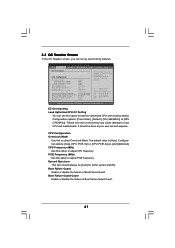
User Manual
Page 49
... disk or hard drive, then you execute ASRock Instant Flash utility, the utility will show the BIOS files and their respective information. 3.4 Advanced Screen In this section, you may set the configurations for CPU WARNING : Setting wrong values in below sections may cause the... Configuration ACPI Configuration Storage Configuration PCIPnP Configuration SuperIO Configuration USB Configuration BIOS Update Utility ASRock Instant Flash Select Screen Select Item Enter Go to your system after BIOS update process completes. 49 Setting wrong values in Flash ROM. Just launch this tool and save...
... disk or hard drive, then you execute ASRock Instant Flash utility, the utility will show the BIOS files and their respective information. 3.4 Advanced Screen In this section, you may set the configurations for CPU WARNING : Setting wrong values in below sections may cause the... Configuration ACPI Configuration Storage Configuration PCIPnP Configuration SuperIO Configuration USB Configuration BIOS Update Utility ASRock Instant Flash Select Screen Select Item Enter Go to your system after BIOS update process completes. 49 Setting wrong values in Flash ROM. Just launch this tool and save...
User Manual
Page 50
...[Enabled]. CPU Thermal Throttle Use this item to enable CPU internal thermal control mechanism to keep the CPU from the chipset. Please set this item to [Disable] if above issue occurs. +F1 F9 F10 ESC Select Screen Select Item Change Option General Help Load Defaults...the Halt State (C1). 3.4.1 CPU Configuration Advanced CPU Configuration Cool 'n' Quiet Secure Virtual Machine Enhanced Halt State L3 Cache Allocation CPU Thermal Throttle BIOS SETUP UTILITY [Auto] [Enabled] [Disabled] [Auto] [Disabled] Enabling this function may reduce CPU voltage and memory frequency, and lead to system...
...[Enabled]. CPU Thermal Throttle Use this item to enable CPU internal thermal control mechanism to keep the CPU from the chipset. Please set this item to [Disable] if above issue occurs. +F1 F9 F10 ESC Select Screen Select Item Change Option General Help Load Defaults...the Halt State (C1). 3.4.1 CPU Configuration Advanced CPU Configuration Cool 'n' Quiet Secure Virtual Machine Enhanced Halt State L3 Cache Allocation CPU Thermal Throttle BIOS SETUP UTILITY [Auto] [Enabled] [Disabled] [Auto] [Disabled] Enabling this function may reduce CPU voltage and memory frequency, and lead to system...


