
User Manual
Page 3
...Specifications 6 1.3 Supported PCI Express VGA Card List for AGI Express Slot (PCI Express x 4 8 1.4 Motherboard Layout 9 1.5 ASRock 8CH I/O 10 2 Installation 11 2.1 Screw Holes 11 2.2 Pre-installation Precautions 11 2.3 CPU Installation 12 2.4 Installation of Heatsink and CPU fan 14 2.5 Installation of Memory Modules (DIMM 15 2.6 Expansion Slots 16 2.7 Dual Graphics Feature 17 2.8 Surround Display Feature 18 2.9 Jumpers Setup 18 2.10 Onboard Headers and Connectors 19 2.11 Serial ATA (SATA) Hard Disks Installation 22 3 BIOS SETUP UTILITY 23 3.1 Introduction 23 3.1.1 BIOS Menu...
...Specifications 6 1.3 Supported PCI Express VGA Card List for AGI Express Slot (PCI Express x 4 8 1.4 Motherboard Layout 9 1.5 ASRock 8CH I/O 10 2 Installation 11 2.1 Screw Holes 11 2.2 Pre-installation Precautions 11 2.3 CPU Installation 12 2.4 Installation of Heatsink and CPU fan 14 2.5 Installation of Memory Modules (DIMM 15 2.6 Expansion Slots 16 2.7 Dual Graphics Feature 17 2.8 Surround Display Feature 18 2.9 Jumpers Setup 18 2.10 Onboard Headers and Connectors 19 2.11 Serial ATA (SATA) Hard Disks Installation 22 3 BIOS SETUP UTILITY 23 3.1 Introduction 23 3.1.1 BIOS Menu...

User Manual
Page 5
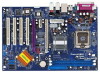
... the motherboard specifications and the BIOS software might be updated, the content of this manual will be subject to the hardware installation. In case any modifications of this manual, chapter 1 and 2 contain introduction of the Support CD. ASRock website http://www.asrock.com 1.1 Package Contents ASRock 775i915PL-SATA2 Motherboard (ATX Form Factor: 12.0-in x 8.0-in Floppy Drive One Serial ATA (SATA) Data Cable (Optional) One Serial ATA (SATA) HDD Power Cable (Optional) One ASRock 8CH I/O 5 Chapter 3 and 4 contain the configuration guide to...
... the motherboard specifications and the BIOS software might be updated, the content of this manual will be subject to the hardware installation. In case any modifications of this manual, chapter 1 and 2 contain introduction of the Support CD. ASRock website http://www.asrock.com 1.1 Package Contents ASRock 775i915PL-SATA2 Motherboard (ATX Form Factor: 12.0-in x 8.0-in Floppy Drive One Serial ATA (SATA) Data Cable (Optional) One Serial ATA (SATA) HDD Power Cable (Optional) One ASRock 8CH I/O 5 Chapter 3 and 4 contain the configuration guide to...
User Manual
Page 6
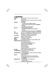
... 1 SATA II device at 3.0Gb/s data transfer rate (Supports "Hot Plug" function) Floppy Port: Supports up to 1 floppy disk drive Audio: 7.1 channels AC'97 Audio PCI LAN: Speed: 802.3u (10/100 Ethernet), supports Wake-On-LAN Hardware Monitor:CPU temperature sensing, Chassis temperature sensing, CPU overheat shutdown to support 4 additional USB 2.0 ports (see CAUTION 3), CPU fan tachometer, CPU Quiet Fan support, Chassis fan tachometer, Voltage monitoring: +12V, +5V, +3.3V, Vcore PCI slots: 4 PCI slots with PCI Specification 2.2 PCI EXPRESS slots: 1 slot with PCIE x 16, 1 slot...
... 1 SATA II device at 3.0Gb/s data transfer rate (Supports "Hot Plug" function) Floppy Port: Supports up to 1 floppy disk drive Audio: 7.1 channels AC'97 Audio PCI LAN: Speed: 802.3u (10/100 Ethernet), supports Wake-On-LAN Hardware Monitor:CPU temperature sensing, Chassis temperature sensing, CPU overheat shutdown to support 4 additional USB 2.0 ports (see CAUTION 3), CPU fan tachometer, CPU Quiet Fan support, Chassis fan tachometer, Voltage monitoring: +12V, +5V, +3.3V, Vcore PCI slots: 4 PCI slots with PCI Specification 2.2 PCI EXPRESS slots: 1 slot with PCIE x 16, 1 slot...

User Manual
Page 7
... Port Audio Jack: Side Speaker / Rear Speaker / Central/Bass / Line In / Front Speaker / Microphone (see CAUTION 8) CAUTION! 1. If you implement Dual Channel Memory Technology, make sure to the installation guide on page 16. 5. For the information of PCI Express VGA card, please refer to read the installation guide of the display adapter controllers, and then you install the PC system. 4. Before you install PCI Express VGA card to the "Supported PCI Express VGA Card List for AGI Express Slot (PCI Express x 4)" on page 15 for USB 2.0 works...
... Port Audio Jack: Side Speaker / Rear Speaker / Central/Bass / Line In / Front Speaker / Microphone (see CAUTION 8) CAUTION! 1. If you implement Dual Channel Memory Technology, make sure to the installation guide on page 16. 5. For the information of PCI Express VGA card, please refer to read the installation guide of the display adapter controllers, and then you install the PC system. 4. Before you install PCI Express VGA card to the "Supported PCI Express VGA Card List for AGI Express Slot (PCI Express x 4)" on page 15 for USB 2.0 works...

User Manual
Page 9
..., blue) 16 Chassis Speaker Header (SPEAKER 1) 17 Chassis Fan Connector (CHA_FAN1) 18 System Panel Header (PANEL1) 19 Infrared Module Connector (IR1) 20 USB 2.0 Header (USB67, Blue) 21 SATA2_EN5 22 USB 2.0 Header (USB45, Blue) 23 Floppy Connector (FLOPPY1) 24 Game Port Header (GAME1) 25 JR1 JL1 Jumper 26 Front Panel Audio Header (AUDIO1) 27 PCI Slots (PCI1- 4) 28 BIOS FWH Chip 29 AGI Express Slot (PCI Express x 4) 30 PCIEX1_EN1 - 4 31 PCI Express Slot (PCIE2) 32 SATA2_EN1 - 4 33 PCI Express Slot (PCIE1) 34 SLI Power 35 Internal Audio Connector: CD1 (Black) 36 ATX Power Connector (ATXPWR1) 9
..., blue) 16 Chassis Speaker Header (SPEAKER 1) 17 Chassis Fan Connector (CHA_FAN1) 18 System Panel Header (PANEL1) 19 Infrared Module Connector (IR1) 20 USB 2.0 Header (USB67, Blue) 21 SATA2_EN5 22 USB 2.0 Header (USB45, Blue) 23 Floppy Connector (FLOPPY1) 24 Game Port Header (GAME1) 25 JR1 JL1 Jumper 26 Front Panel Audio Header (AUDIO1) 27 PCI Slots (PCI1- 4) 28 BIOS FWH Chip 29 AGI Express Slot (PCI Express x 4) 30 PCIEX1_EN1 - 4 31 PCI Express Slot (PCIE2) 32 SATA2_EN1 - 4 33 PCI Express Slot (PCIE1) 34 SLI Power 35 Internal Audio Connector: CD1 (Black) 36 ATX Power Connector (ATXPWR1) 9

User Manual
Page 16
PCIE2 (PCIE x 1 slot) is completely seated on the slot. Please check the jumper settings on this motherboard. Step 3. Align the card connector with x16 lane width graphics cards. 2.6 Expansion Slots (PCI, PCI Express, and AGI Express Slots (PCI Express x 4)) There are used to install expansion cards that the power supply is switched off or the power cord is used for the card before you intend to the chassis with screws. 16 AGI Express slot (PCI Express x 4): AGI Express slot (PCI Express x 4) is unplugged. Before installing the expansion card, please...
PCIE2 (PCIE x 1 slot) is completely seated on the slot. Please check the jumper settings on this motherboard. Step 3. Align the card connector with x16 lane width graphics cards. 2.6 Expansion Slots (PCI, PCI Express, and AGI Express Slots (PCI Express x 4)) There are used to install expansion cards that the power supply is switched off or the power cord is used for the card before you intend to the chassis with screws. 16 AGI Express slot (PCI Express x 4): AGI Express slot (PCI Express x 4) is unplugged. Before installing the expansion card, please...
User Manual
Page 17
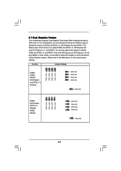
... correct jumper settings. When installing the add-on VGA cards to this feature is to enable PCIE2 slot (PCIE x 1), AGI Express slot (only PCI Express x 1), and SATA II. 2.7 Dual Graphics Feature This motherboard supports Dual Graphics Technology. You can also adjust the jumpers to decide the function of this motherboard, you are allowed choosing two different ways to disable PCIE2 slot (PCIE x 1) and SATA II. The default value of PCIE2 slot (PCIE x 1), AGI Express slot, and SATA II. Function Jumper Settings 2_3 PCIE x 1_EN4 2_3 PCIE...
... correct jumper settings. When installing the add-on VGA cards to this feature is to enable PCIE2 slot (PCIE x 1), AGI Express slot (only PCI Express x 1), and SATA II. 2.7 Dual Graphics Feature This motherboard supports Dual Graphics Technology. You can also adjust the jumpers to decide the function of this motherboard, you are allowed choosing two different ways to disable PCIE2 slot (PCIE x 1) and SATA II. The default value of PCIE2 slot (PCIE x 1), AGI Express slot, and SATA II. Function Jumper Settings 2_3 PCIE x 1_EN4 2_3 PCIE...
User Manual
Page 18
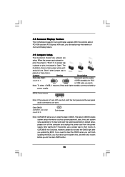
... add-on these 2 pins. The data in CMOS. 2.8 Surround Display Feature This motherboard supports Surround Display upgrade. Jumper Setting Description PS2_USB_PWR1 1_2 (see p.9 No. 25) JR1 JL1 Note: If the jumpers JL1 and JR1 are setup. The illustration shows a 3-pin jumper whose pin1 and pin2 are "Short" when jumper cap is placed on PCI VGA card and PCI Express VGA card, you update the BIOS. To clear and reset the system parameters to enable 2_3 +5VSB (standby...
... add-on these 2 pins. The data in CMOS. 2.8 Surround Display Feature This motherboard supports Surround Display upgrade. Jumper Setting Description PS2_USB_PWR1 1_2 (see p.9 No. 25) JR1 JL1 Note: If the jumpers JL1 and JR1 are setup. The illustration shows a 3-pin jumper whose pin1 and pin2 are "Short" when jumper cap is placed on PCI VGA card and PCI Express VGA card, you update the BIOS. To clear and reset the system parameters to enable 2_3 +5VSB (standby...
User Manual
Page 19
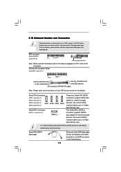
... the SATA hard disk or the SATA connector on the motherboard. 19 Serial ATA (SATA) Data Cable Either end of your IDE device vendor for the details. Placing jumper caps over these headers and connectors. The current SATA interface allows up to Pin1 Note: Make sure the red-striped side of the cable is recommended to plug SATAII HDD to SATAII connector and connect SATAI HDD to the instruction of the SATA data cable...
... the SATA hard disk or the SATA connector on the motherboard. 19 Serial ATA (SATA) Data Cable Either end of your IDE device vendor for the details. Placing jumper caps over these headers and connectors. The current SATA interface allows up to Pin1 Note: Make sure the red-striped side of the cable is recommended to plug SATAII HDD to SATAII connector and connect SATAI HDD to the instruction of the SATA data cable...

User Manual
Page 21
...) CPU Fan Connector (4-pin CPU_FAN1) (see p.9 No. 5) ATX Power Connector (20-pin ATXPWR1) (see p.9 No. 34) Please connect an ATX 12V power supply to this connector. Please connect the chassis speaker to this header. GND +12V CHA_FAN_SPEED Please connect a chassis fan cable to the ground pin. Please connect an ATX power supply to this connector and match the black wire to this connector. SLI POWER_1 It is not necessary to use this connector, but please connect it with a hard disk power connecor when two graphics cards are plugged to...
...) CPU Fan Connector (4-pin CPU_FAN1) (see p.9 No. 5) ATX Power Connector (20-pin ATXPWR1) (see p.9 No. 34) Please connect an ATX 12V power supply to this connector. Please connect the chassis speaker to this header. GND +12V CHA_FAN_SPEED Please connect a chassis fan cable to the ground pin. Please connect an ATX power supply to this connector and match the black wire to this connector. SLI POWER_1 It is not necessary to use this connector, but please connect it with a hard disk power connecor when two graphics cards are plugged to...

User Manual
Page 24
... display the system overview BIOS SETUP UTILITY Main Advanced H/W Monitor Boot Security Exit System Overview System Time System Date [14:00:09] [Thu 05/05/2005] BIOS Version : 775i915PL-SATA2 BIOS P1.00 Processor Type : Intel (R) CPU 3.40 GHz (64bit supported) Processor Speed : 3400 MHz Microcode Update : F34/14 Cache Size : 1024KB Total Memory DIMM 1 DIMM 2 : 512MB Dual-Channel Memory Mode : 256MB/166MHz (DDR333) : 256MB/166MHz (DDR333) Use [Enter], [TAB] or [SHIFT-TAB] to select items To change option...
... display the system overview BIOS SETUP UTILITY Main Advanced H/W Monitor Boot Security Exit System Overview System Time System Date [14:00:09] [Thu 05/05/2005] BIOS Version : 775i915PL-SATA2 BIOS P1.00 Processor Type : Intel (R) CPU 3.40 GHz (64bit supported) Processor Speed : 3400 MHz Microcode Update : F34/14 Cache Size : 1024KB Total Memory DIMM 1 DIMM 2 : 512MB Dual-Channel Memory Mode : 256MB/166MHz (DDR333) : 256MB/166MHz (DDR333) Use [Enter], [TAB] or [SHIFT-TAB] to select items To change option...

User Manual
Page 25
... Chipset Configuration ACPI Configuration IDE Configuration PCIPnP Configuration Floppy Configuration SuperIO Configuration USB Configuration Configure CPU Select Screen Select Item Enter Go to malfunction. CPU Host Frequency While entering setup, BIOS auto detects the present CPU host frequency of Boot Failure Guard. Boot Failure Guard Enable or disable the feature of this section may cause system to Sub Screen F1 General Help F9 Load Defaults F10 Save and Exit ESC Exit v02.54 (C) Copyright 1985-2005, American Megatrends, Inc. BIOS SETUP UTILITY Main Advanced H/W Monitor Boot...
... Chipset Configuration ACPI Configuration IDE Configuration PCIPnP Configuration Floppy Configuration SuperIO Configuration USB Configuration Configure CPU Select Screen Select Item Enter Go to malfunction. CPU Host Frequency While entering setup, BIOS auto detects the present CPU host frequency of Boot Failure Guard. Boot Failure Guard Enable or disable the feature of this section may cause system to Sub Screen F1 General Help F9 Load Defaults F10 Save and Exit ESC Exit v02.54 (C) Copyright 1985-2005, American Megatrends, Inc. BIOS SETUP UTILITY Main Advanced H/W Monitor Boot...

User Manual
Page 26
... installed CPU does not support Hyper-Threading technology. Enhance Halt State All processors support the Halt State (C1). No-Excute Memory Protection No-Execution (NX) Memory Protection Technology is an enhancement to [Enabled] if using Microsoft® Windows® XP, or Linux kernel version 2.4.18 or higher. Intel (R) SpeedStep(tm) tech. Set to the IA-32 Intel Architecture. This should be enabled in order to boot legacy...
... installed CPU does not support Hyper-Threading technology. Enhance Halt State All processors support the Halt State (C1). No-Excute Memory Protection No-Execution (NX) Memory Protection Technology is an enhancement to [Enabled] if using Microsoft® Windows® XP, or Linux kernel version 2.4.18 or higher. Intel (R) SpeedStep(tm) tech. Set to the IA-32 Intel Architecture. This should be enabled in order to boot legacy...

User Manual
Page 28
... the onboard AC'97 Audio feature. VCCM Use this feature is [PCIE/PCI]. If [Power Off] is [Auto]. Configuration options: [High], and [Low]. The default value of this to boot up when the power recovers. PCI Devices Power On Use this feature is selected, the AC/Power remains off when the power recovers. The default value of this item to enable or disable PCI devices to select [PCIE/PCI] or [PCI/PCIE] as the boot graphic adapter priority. and [15 DRAM Clocks]. OnBoard LAN...
... the onboard AC'97 Audio feature. VCCM Use this feature is [PCIE/PCI]. If [Power Off] is [Auto]. Configuration options: [High], and [Low]. The default value of this to boot up when the power recovers. PCI Devices Power On Use this feature is selected, the AC/Power remains off when the power recovers. The default value of this item to enable or disable PCI devices to select [PCIE/PCI] or [PCI/PCIE] as the boot graphic adapter priority. and [15 DRAM Clocks]. OnBoard LAN...

User Manual
Page 29
... [SATA 1, SATA 2, SATA 3, SATA 4], and [IDE 1, SATA 2, SATA 4]. The default value of this item to enable or disable PS/2 keyboard to power on the system from the power-soft-off mode. Configuration options: [Enabled], [Disabled]. If it is [IDE]. The default value of this item to enable or disable RTC (Real Time Clock) to turn on the system. 3.3.4 IDE Configuration BIOS SETUP UTILITY Advanced IDE Configuration ATA/IDE Configuration OnBoard SATAII Controller SATAII Operation Mode SATA1 SATA2 SATA3 SATA4 IDE1 Master IDE1 Slave SATAII [Enhanced] [Enabled] [IDE] [Hard Disk] [Not...
... [SATA 1, SATA 2, SATA 3, SATA 4], and [IDE 1, SATA 2, SATA 4]. The default value of this item to enable or disable PS/2 keyboard to power on the system from the power-soft-off mode. Configuration options: [Enabled], [Disabled]. If it is [IDE]. The default value of this item to enable or disable RTC (Real Time Clock) to turn on the system. 3.3.4 IDE Configuration BIOS SETUP UTILITY Advanced IDE Configuration ATA/IDE Configuration OnBoard SATAII Controller SATAII Operation Mode SATA1 SATA2 SATA3 SATA4 IDE1 Master IDE1 Slave SATAII [Enhanced] [Enabled] [IDE] [Hard Disk] [Not...

User Manual
Page 31
... enhance hard disk performance by optimizing the hard disk timing. Block (Multi-Sector Transfer) The default value of PCI clocks for compatible IDE devices. S.M.A.R.T. It is [Auto]. PCI IDE BusMaster Use this item to enable 32-bit access to maximize the IDE hard disk data transfer rate. 3.3.5 PCIPnP Configuration BIOS SETUP UTILITY Advanced PCI / PnP Configuration WARNING: Setting wrong values in units of this item to enable or disable the S.M.A.R.T. (Self-Monitoring, Analysis, and Reporting Technology) feature. PCI Latency Timer PCI IDE BusMaster [32] [Enabled...
... enhance hard disk performance by optimizing the hard disk timing. Block (Multi-Sector Transfer) The default value of PCI clocks for compatible IDE devices. S.M.A.R.T. It is [Auto]. PCI IDE BusMaster Use this item to enable 32-bit access to maximize the IDE hard disk data transfer rate. 3.3.5 PCIPnP Configuration BIOS SETUP UTILITY Advanced PCI / PnP Configuration WARNING: Setting wrong values in units of this item to enable or disable the S.M.A.R.T. (Self-Monitoring, Analysis, and Reporting Technology) feature. PCI Latency Timer PCI IDE BusMaster [32] [Enabled...
User Manual
Page 32
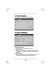
... floppy drive connected to the system. +F1 F9 F10 ESC Select Screen Select Item Change Option General Help Load Defaults Save and Exit Exit v02.54 (C) Copyright 1985-2005, American Megatrends, Inc. 3.3.7 Super IO Configuration BIOS SETUP UTILITY Advanced Configure Super IO Chipset OnBoard Floppy Controller Serial Port Address Infrared Port Address Parallel Port Address Parallel Port Mode EPP Version ECP Mode DMA Channel Parallel Port IRQ OnBoard Game Port OnBoard MIDI Port [Enabled] [3F8 / IRQ4] [Disabled] [378] [ECP + EPP] [1.9] [DMA3] [IRQ7] [Enabled] [Disabled] Allow BIOS...
... floppy drive connected to the system. +F1 F9 F10 ESC Select Screen Select Item Change Option General Help Load Defaults Save and Exit Exit v02.54 (C) Copyright 1985-2005, American Megatrends, Inc. 3.3.7 Super IO Configuration BIOS SETUP UTILITY Advanced Configure Super IO Chipset OnBoard Floppy Controller Serial Port Address Infrared Port Address Parallel Port Address Parallel Port Mode EPP Version ECP Mode DMA Channel Parallel Port IRQ OnBoard Game Port OnBoard MIDI Port [Enabled] [3F8 / IRQ4] [Disabled] [378] [ECP + EPP] [1.9] [DMA3] [IRQ7] [Enabled] [Disabled] Allow BIOS...
User Manual
Page 34
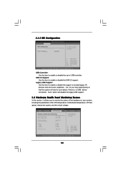
... no USB device connected, "Auto" option will start to enable or disable the use of the CPU temperature, motherboard temperature, CPU fan speed, chassis fan speed, and the critical voltage. Or you to monitor the status of the hardware on your system, including the parameters of USB controller. 3.3.8 USB Configuration BIOS SETUP UTILITY Advanced USB Configuration USB Controller USB 2.0 Support Legacy USB Support [Enabled] [Enabled] [Disabled] To enable or disable the onboard USB controllers. +F1 F9 F10 ESC Select Screen Select Item Change Option General Help Load Defaults Save...
... no USB device connected, "Auto" option will start to enable or disable the use of the CPU temperature, motherboard temperature, CPU fan speed, chassis fan speed, and the critical voltage. Or you to monitor the status of the hardware on your system, including the parameters of USB controller. 3.3.8 USB Configuration BIOS SETUP UTILITY Advanced USB Configuration USB Controller USB 2.0 Support Legacy USB Support [Enabled] [Enabled] [Disabled] To enable or disable the onboard USB controllers. +F1 F9 F10 ESC Select Screen Select Item Change Option General Help Load Defaults Save...

User Manual
Page 36
...Item Enter Change F1 General Help F9 Load Defaults F10 Save and Exit ESC Exit v02.54 (C) Copyright 1985-2005, American Megatrends, Inc. 36 Boot From Network Use this section, you may set to enable or disable the Boot From Network feature. BIOS SETUP UTILITY Main Advanced H/W Monitor Boot Security Exit Security Settings Supervisor Password : Not Installed User Password : Not Installed Change Supervisor Password Change User Password Install or Change the password. 3.5.1 Boot Settings Configuration BIOS SETUP UTILITY Boot Boot Settings Configuration Boot From Network...
...Item Enter Change F1 General Help F9 Load Defaults F10 Save and Exit ESC Exit v02.54 (C) Copyright 1985-2005, American Megatrends, Inc. 36 Boot From Network Use this section, you may set to enable or disable the Boot From Network feature. BIOS SETUP UTILITY Main Advanced H/W Monitor Boot Security Exit Security Settings Supervisor Password : Not Installed User Password : Not Installed Change Supervisor Password Change User Password Install or Change the password. 3.5.1 Boot Settings Configuration BIOS SETUP UTILITY Boot Boot Settings Configuration Boot From Network...
User Manual
Page 38
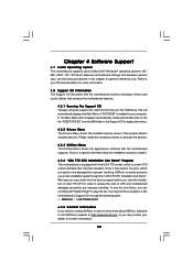
... handling, ASRock sincerely presents you can run Microsoft® Media Player® to your computer. Refer to play the file. Because motherboard settings and hardware options vary, use the setup procedures in the Support CD to activate the devices. 4.2.3 Utilities Menu The Utilities Menu shows the applications software that Intel has released. Please install the necessary drivers to display the menus. 4.2.2 Drivers Menu The Drivers Menu shows the available devices drivers if the...
... handling, ASRock sincerely presents you can run Microsoft® Media Player® to your computer. Refer to play the file. Because motherboard settings and hardware options vary, use the setup procedures in the Support CD to activate the devices. 4.2.3 Utilities Menu The Utilities Menu shows the applications software that Intel has released. Please install the necessary drivers to display the menus. 4.2.2 Drivers Menu The Drivers Menu shows the available devices drivers if the...


